USO0RE42265E
(19) United States (12) Reissued Patent Hughes (54)
(10) Patent Number: US RE42,265 E (45) Date of Reissued Patent: Apr. 5, 2011 (56)
CUT RESISTANT YARNS FOR GLOVE AND SLEEVES, GLOVES AND SLEEVES MADE WITH SUCH YARNS AND METHODS OF MAKING SUCH CUT RESISTANT YARNS
(75) Inventor:
References Cited U.S. PATENT DOCUMENTS
Grif?th W. Hughes, Wayne, PA (US)
4,350,731 A *
9/1982
4,509,320 A
4/1985 M6666
5,464,684 A * 5,628,172
(73) Assignee: Banom, Inc., Wayne, PA (US)
A
11/1995
Siracusano
Vogelsang 6161. .......... .. 442/198
*
5/1997
K616166661.
5,721,179 A *
2/1998
$166161. ..................... .. 442/203
2004/0128973 Al
.....
. . . ..
57/210
7/2004 Morikawa
(21) Appl.No.: 12/182,272
* cited by examiner
(22) Filed:
Primary Examiner * Shaun R Hurley
Jul. 30, 2008
................. .. 442/270
(74) Attorney, Agent, or Firm * Caesar, Rivise, Bernstein, Cohen & PokotiloW, Ltd.
Related US. Patent Documents
Reissue of:
(64) Patent No.: Issued:
7,185,481
(57)
Mar. 6, 2007
Cut resistant yarns suitable for knitting gloves and sleeves and
Appl. No.:
11/180,157
Filed:
Jul. 13, 2005
ABSTRACT
methods of making the yarns are disclosed. The yarns are made up of a bundle of continuous ?laments formed of a
US. Applications:
synthetic material, e.g., polyethylene, polypropylene, nylon
(60)
Provisional application No. 60/653,010, ?led on Feb. 15, 2005.
or polyole?n, and a stretchable yarn, e.g., Spandex® or Lycra®. The yarns are made in such a manner that When
(51)
Int. Cl. D02G 3/22
to one another and to the longitudinal axis of the yarn so that items made from them Will not tWist or curl up, yet Will
(52) (58)
US. Cl. .............................................. .. 57/210; 57/3 Field of Classi?cation Search ................... .. 57/210
completed the continuous ?laments are substantially parallel (2006.01)
provide good resistance to cutting.
See application ?le for complete search history.
17 Claims, 4 Drawing Sheets
300 4 I F _ ‘F
3
12
'/1/\\ \
I \
' \
\
v
‘f
‘
I
7
\_
'
\
K
V
\ I
J '
\ \
\
US. Patent
Apr. 5, 2011
Sheet 1 of4
US RE42,265 E
F/GJ
FIG. 3 (PRIOR ARn
US. Patent
US RE42,265 E
US. Patent
Apr. 5, 2011
Sheet 4 of4
US RE42,265 E
20,200,300
FIG. 9
20,200,300
\ (/ FIG. 10
US RE42,265 E 1
2
CUT RESISTANT YARNS FOR GLOVE AND SLEEVES, GLOVES AND SLEEVES MADE WITH SUCH YARNS AND METHODS OF MAKING SUCH CUT RESISTANT YARNS
helix spacing of several tWists of stretchable yarn per inch of the ?lament yarn (i.e., the ?ber bundle). When the tension is relaxed, the resulting combined yarn is a stretchable ?lament yarn that can be knit into gloves or sleeves.
Unfortunately, the plying process forces the ?lament yarn to tWist in the same direction as the stretchable yarn is plied
Matter enclosed in heavy brackets [ ] appears in the original patent but forms no part of this reissue speci?ca
(Wound). When this happens tWo things occur. First, the abil ity of each ?ber of the bundle to roll individually is restricted, thus reducing cut resistance of the combined yarn. Second,
tion; matter printed in italics indicates the additions made by reissue.
the combined yarn then develops a tWist to it. When gloves and arm sleeves are knitted, any yarn that is tWisted, such as the combined yarn just described, Will cause
CROSS-REFERENCE TO RELATED APPLICATIONS
a torque. When this happens, glove ?ngers become tWisted and arm sleeves begin to Wrap around the arm, Which can
This application claims priority from provisional US.
15
Patent Application No. 60/ 653,010, ?led on Feb. 15, 2005.
reduce cut resistance because it is noW restricting the ability of the sleeve to stretch. The industry calls this torque in the yarn an “S.” To counteract S torque, it is a common practice in
the industry to add another yarn tWisted in the opposite direc
STATEMENT REGARDING FEDERALLY SPONSORED RESEARCH OR DEVELOPMENT
tion as the stretchable yarn. This additional yarn is frequently 20
combined yarn to be ?at and a sleeve knitted of it to relax. The Z yarn can be of lesser denier than the stretchable yarn and
INCORPORATION-BY-REFERENCE OF MATERIAL SUBMITTED ON A COMPACT DISK
can be Wrapped around the stretchable yarn in the opposite 25
“Not Applicable”
parallel to it and the tWo combined yarns knitted together so that the tWist provided by both yarns counteract each other. 30
2. Description of Related Art Knitted “Wor ” gloves formed of conventional materials, such as cotton or poly-cotton provide some measure of pro
35
tection from injury and some cushioning for the hand of Workers, but are notoriously de?cient insofar as providing resistance to cutting. Thus, it is a common practice to knit Work gloves of cut resistant yarns. Mo st cut resistant yarns are formed of ?lamentsiie, they are a bundle of continuous ?laments or ?bers. The term ?laments and ?bers are used
While the use of a Z yarn has the foregoing advantage, it is not Without cost. In this regard the use of the additional reverse tWisted Z yarn increases the cost of the resulting yarn
due to the cost of the Z yarn itself. Moreover, if the Z yarn is counter-Wrapped about the stretchable yarn, there is the addi tional manufacturing costs inherent in effecting that Wrap ping action. If the Z yarn is run parallel to the stretchable yarn and then the tWo are knitted together, the resulting glove or sleeve Will be considerably thicker (Which may be undesir
able from the standpoint of ?exibility). To keep costs doWn, it is a common practice to use loW cost materials for the Z yarn. 40
Unfortunately, such loW cost materials are inferior in that they are not cut resistant. When these loW cost Z yarns are added to
interchangeably herein, and may be given the same general meaning, e.g., microscopically, looking like a bundle of ?sh
a glove or sleeve, they tend to break doWn or cut more easily.
ing lines. Cut resistance is obtained by several factors. One factor can
direction to counteract the tWist. Alternatively, the Z yarn can be of the same denier as the stretchable yarn and can be run
BACKGROUND OF THE INVENTION
1. Field of Invention This invention relates generally to cut resistant yarns and more particularly to cut resistant yarn for gloves or sleeves.
referred to as the “Z” or “Zed” yarn. The use of a Z yarn in the
combined yarn alloWs the ?ngers of a glove knitted from the
“Not Applicable”
45
When this happens the knitted product falls apart. Thus, While the above yarns may be generally suitable for their intended purposes, they leave something to be desired
be deemed to be the tendency to produce “slippage.” In par
from one or more of the folloWing factors, ease of manufac
ticular, When a blade or other sharp instrument passes over the
ture, effectiveness, reliability and cost.
yarn, it slides along the smooth surfaces of the ?ber bundle, rather than catching on the yarn, Which action Would result in a tendency to cut the yarn. Tensile strength is another factor in
BRIEF SUMMARY OF THE INVENTION 50
establishing cut resistance. In this regard, the shear strength of
This invention is directed to cut resistant, stretchable yarns and method of making them. The yarns are suitable for knit
the ?ber is selected to be so strong that it prevents the ?ber from breaking. The abrasive action of the ?ber is also a factor,
ting gloves and sleeves. The yarns each have a longitudinal
since the harder the ?ber, the greater the tendency to dull the
cutting edge, thereby reducing the tendency of the ?ber to be
55
cut. Another signi?cant factor is What may be called “rolling.” This is the ability of the ?bers of the yarn to tWist or roll about their longitudinal axis as the blade moves across the yarn.
Such rolling action enhances cut resistance by denying the cutting edge a stationary surface to cut.
60
Filament yarns, due to their structure, Will not stretch.
Stretchability is of considerable importance in order to readily knit a viable, loW-cost glove. Consequently, the knit ted glove industry, typically plies these yarns With an elastic or stretchable yarn such as Spandex® or Lycra® alongside the ?lament yarn and then Wraps the stretchable yarn under tension in a helical pattern around the ?lament yarn, With the
axis. Each yarn comprises a bundle of continuous ?laments formed of a synthetic material and a stretchable yarn. In accordance With one aspect of the invention each of the continuous ?laments of the bundle of ?laments has a longi tudinal axis. The bundle of ?laments is tWisted in a ?rst rotational direction With respect to the longitudinal axis of the yarn to apply a torque to the bundle in the ?rst rotational direction. The stretchable yarn is Wound under tension about the bundle of ?laments in a helical pattern in a second and
opposite rotational direction With respect to the longitudinal 65
axis of the yarn to apply a torque to the bundle in the second rotational direction. The torque in the ?rst direction substan
tially cancels the torque in the second direction, whereupon after the stretchable yarn has been made the longitudinal axes
US RE42,265 E 4
3 of the ?laments of the bundle are substantially parallel to one another and to the longitudinal axis of yarn. In accordance With another aspect of this invention the
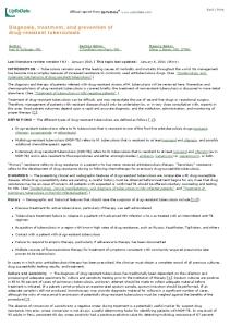
FIG. 6 is an illustration of the alternative embodiment of
the ?nished cut resistant, stretchable yarn shoWn made by the process shoWn in FIGS. 4 and 5; FIG. 7 is an illustration shoWing the process of making another alternative embodiment of a cut resistant, stretchable yarn constructed in accordance With another aspect of this
stretchable yarn is of substantially smaller denier than the bundle of ?laments and is initially under tension to cause it to stretch. Each of the continuous ?laments of the bundle of
?laments has a longitudinal axis and is oriented initially par allel to the other ?laments of the bundle. The bundle of
invention;
?laments is helically Wound about the stretched stretchable
of the ?nished cut resistant, stretchable yarn shoWn made by the process shoWn in FIG. 7; FIG. 9 is an illustration of an exemplary glove knitted of any of the cut resistant yarns of this invention; and
FIG. 8 is an illustration of the other alternative embodiment
yarn to apply a torque in a ?rst rotational direction to the ?laments of the bundle to cause them to tWist With respect to one another in the ?rst rotational direction. The bundle of ?laments and the stretchable yarn are thereafter tWisted in a
FIG. 10 is an illustration of an exemplary arm sleeve knit
ted of any of the cut resistant yarns of this invention.
second and opposite rotational direction With respect to the longitudinal axis of the yarn to apply a torque to the bundle and to the stretchable yarn in the second rotational direction. The torque in the second direction substantially cancels the
DETAILED DESCRIPTION OF THE INVENTION
Referring noW to the various ?gures of the draWing Wherein like reference characters refer to like parts, there is
torque in the ?rst direction, Whereupon the bundle of ?la ments again assumes the condition Wherein all of the ?la
20
ments of the bundle are parallel to one another and to the
longitudinal axis of the yarn and the stretchable yarn tWists about its longitudinal axis and moves to a position Wherein it
is helically disposed around the parallel ?laments of the bundle. In accordance With still another aspect of this invention the continuous ?laments of the bundle of ?laments are pre tWisted With respect to one another Whereby the ?laments have a torque in a ?rst rotational direction applied to them.
25
This bundle of pre-tWisted ?laments is helically Wound about
30
structed in accordance With one exemplary embodiment of this invention shoWn in the process of being made by one method of this invention. Before describing the details of that yarn and the method of making it, a brief description of the prior art yarns discussed above is in order. To that end, in FIG. 2 there is shoWn a portion of a prior art yarn 2 in the form of a bundle of single, continuous ?laments 4. The yarn 2 has a longitudinal axis 6. Each of the ?laments 4 of the bundle is of the same material, e.g., a conventional
material such as polyethylene, polypropylene, nylon and polyole?n, and has its oWn longitudinal axis 8. The ?laments 4 of the bundle are disposed in a side-by-side array and are
the small denier stretchable yarn to apply a torque in a second rotational direction to those ?laments to cause them to
spaced slightly from one another, but With their respective longitudinal axes 8 being generally parallel to one another and to the longitudinal axis 6 of the yarn 2. Accordingly, as discussed above, each of the ?laments 4 of the bundle can roll
untWist With respect to one another in the second rotational
direction, i.e., the torque in the second direction substantially cancels the torque in the ?rst direction, Whereupon the bundle of ?laments again assumes the condition Wherein all of the
or tWist about its oWn longitudinal axis to enhance the cut resistance of a glove or sleeve knitted from such a yarn. In FIG. 3 there is shoWn a stretchable yarn 10 for use in
?laments of the bundle are parallel to one another and to the
longitudinal axis of the yarn, and the stretchable yarn tWists about its longitudinal axis and moves to a position Wherein it
shoWn at 20 in FIG. 1 a cut resistant, stretchable yarn con
is helically disposed around the parallel ?laments of the
knitted gloves and arm sleeves. The stretchable yarn 10 is like that discussed above. In particular, the yarn 10 is in the form
bundle.
of a bundle of continuous ?laments 4, but With a stretchable or
Other aspects of this invention entail methods of producing the cut resistant, stretchable yarns summarized above and of gloves and sleeves formed of such yarns.
elastic yarn 12, e.g., Spandex®, Lycra® or similar continuous ?lament materials, Wound helically about the ?laments of the
40
45
BRIEF DESCRIPTION OF SEVERAL VIEWS OF THE DRAWINGS
The invention Will be described in conjunction With the
50
folloWing draWings in Which like reference numerals desig nate like elements and Wherein: FIG. 1 is an illustration in the form of an isometric vieW of a cut resistant yarn constructed in accordance With this inven
tion in the process of being made;
55
axes, thereby resulting in a yarn Whose cut-resistance is reduced. Moreover, the resulting yarn 10 itself develops a tWist to it, Whereupon the ?ngers of gloves or the body of arm
?laments; 60
sleeves knitted of such a yarn Will tWist up. As also pointed
out above, in order to prevent the tendency of gloves and sleeves knitted of such yarns from curling up, the yarn 10 is commonly Wound With a Z yarn in the opposite rotational direction to counteract the torque applied by the stretchable
able yam constructed in accordance With another aspect of
this invention; FIG. 5 is an illustration of a later step in the process shoWn
As Will be appreciated by those skilled in the art, When the stretchable yarn 12 is placed under tension and then Wound helically about the periphery of the bundle of ?laments 4 it creates a torque on those ?laments, Whereupon When the resulting yarn is released, the ?laments 4 tWist and become effectively “locked-up.” In particular, as discussed above this tWisting action restrains those ?laments so that they are not
able to roll individually about their respective longitudinal
FIG. 2 is an illustration in the form of an isometric vieW of a prior art cut resistant yarn formed of a bundle of continuous FIG. 3 is an illustration in the form of an isometric vieW of a portion of a prior art cut resistant stretchable yarn; FIG. 4 is an illustration shoWing a step in a process of making an alternative embodiment of a cut resistant, stretch
bundle in one rotational direction With respect to the longitu dinal axis 6 of the bundle. In the embodiment shoWn, the stretchable yarn 12 is Wrapped or Wound in the counterclock Wise direction designated by the arroW R1.
in FIG. 4 for making the alternative embodiment of the cut
yarn. FIG. 1 illustrates the yarn 20 of this invention, Which over
resistant, stretchable yarn;
comes the disadvantage of the prior art yarns. In particular, in
65
US RE42,265 E 5
6
accordance With one aspect of this invention, the yarn 20 is a cut resistant, curl or tWist resistant, stretchable yarn made up of plural continuous ?laments 4, that are arranged in an array or bundle so that all of their respective axes 8 are parallel to one another. A tensioned, stretchable ?ber or yarn 12 is Wrapped or Wound about the bundle of ?laments 4, in a helical
apply a torque in that rotational direction to the ?laments 4. This action causes the ?laments 4 to tWist With respect to one
another in that rotational direction as clearly shoWn in FIG. 4. The bundle of tWisted continuous ?laments 4 and the stretched, but untWisted, stretchable yarn 12 are then tWisted as a unit as shoWn in FIG. 5. In particular, they are tWisted in a second and opposite rotational direction, e.g., clockWise as
pattern about the yarn’s longitudinal axis 6 in one rotational direction, e.g., the counterclockwise direction R1, to render the resulting yarn stretchable. HoWever, at the same time that
shoWn by the direction of the arroW R2, by apparatus like the apparatus 100 shoWn in FIG. 1, to apply a torque to the bundle of ?laments 4 and to the stretched ?ber 12 in that second rotational direction R2. The torque that is produced on the ?laments 4 and stretchable ?ber 12 in the R2 direction from the tWisting action substantially cancels the torque on the ?laments 4 in the ?rst (R1) direction that resulted from Wind ing that bundle of ?laments about the ?ber 12. Thus, When the yarn 200 is released from the apparatus 100 the ?laments 4 of
the stretchable yarn 12 is Wound in the one rotational direc
tion R1 about the bundle of ?laments 4, the entire bundle of ?laments is itself rotated, by means of apparatus 100, in the
opposite rotational direction R2 shoWn by the clockWise directed arroW. The apparatus 100 to apply the counter-rota tion to the yarn can be any suitable device for gripping the
bundle and tWisting it in the rotational direction R2.
the bundle again assume their parallel condition, i.e., their condition prior to being Wound about the ?ber 12. The release of the yarn 200 from the apparatus enables the stretched,
The counter-rotation of the ?lament bundle as the stretch
able yam is being applied (Wound about the ?laments) applies a torque that is in the opposite direction to the torque applied by the stretchable yarn as it is Wound about the bundle. The tWo torques essentially cancel each other so that end result is that When the yarn 20 is completed and released from the equipment for making it the ?laments 4 of the yarn 20 run parallel to one another and can roll individually about their oWn respective longitudinal axis. This later feature increases the cut resistance, While the former feature ensures that the resulting yarn itself isn’t tWisted. Accordingly, there is no
20
?laments 4 and to assume a helical orientation. Thus, the 25
resulting, i.e., ?nished, yarn 200 looks like that shoWn in FIG. 6.
need to make use of an oppositely Wound Z yarn, as has
typi?ed prior art stretchable yarns. Any suitable materials can be used for making the yarn 20. For example, the continuous ?laments can be selected from
stretchable yarn 12 to relax. Since it Will have been tWisted
about its longitudinal axis by the apparatus 100, and since it is of small denier, the stretchable yarn attempts to untWist, thereby causing it to move outside of the bundle parallel
30
It should be pointed out at this juncture that the direction of tWisting of the ?laments as described above is merely exem plary. Thus, the ?laments 4 of the bundle can be tWisted about the stretched ?ber 12 in the clockWise direction and then that bundle and the stretched stretchable ?ber can be rotated as a
the group comprising polyethylene, polypropylene, nylon
unit in the counterclockwise direction by the apparatus 100 to
and polyole?n. Those materials can have a denier in the range
result in a yarn exhibiting the same properties as the yarn 200
of approximately 100 to approximately 1200. The stretchable yarn can be selected from the group comprising Spandex® and Lycra® and can have a denier in the range of approxi mately 40 to approximately 70. One particularly suitable yarn
35
for a glove, like that shoWn in FIG. 9, or an arm sleeve like that
shoWn in FIG. 10 is formed of continuous ?laments of Dyneema, having a denier of 400 and a stretchable yarn of Lycra®, having a denier of 40 denier. It should be understood that these materials and their denier are merely exemplary of numerous materials and deniers Which can be used, depend
40
In FIG. 8 there is shoWn an alternative embodiment of a stretchable, cut resistant and curl or tWist resistant yarn 300 constructed in accordance With this invention. That yarn is made by an alternative method of this invention shoWn in
FIG. 7. The process of making the yarn 300 is slightly differ ent than the process from making the yarn 200, although the
resulting yarns are visually similar. In particular, the making
ing upon the ultimate yarn and/or product to be made, e.g.,
knitted, therefrom.
described above but Whose appearance is slightly different, i.e., the direction of the spiral of the stretchable yarn being opposite to that shoWn in FIG. 6.
45
In FIG. 6 there is shoWn an alternative embodiment of a stretchable, cut resistant, curl or tWist resistant yarn 200 con structed in accordance With this invention. That yarn is made by an alternative method of this invention shoWn in FIGS. 4
of the yarn 300 also entails providing a stretchable ?ber or yarn 12, like that described With reference to the method shoWn in FIGS. 4-6, and stretching or tensioning it so that it
extends generally linearly. A bundle of continuous ?laments 4 is provided to complete the yarn. HoWever, unlike the method shoWn in FIGS. 4-5, the ?laments 4 of the bundle of
and 5. As Will be seen, unlike the production of the yarn 20, the production of the yarn 200 does not entail helically Wrap ping the stretchable yam 12 about the bundle of ?laments 4, although When the yarn is ?nished the stretchable yarn Will extend helically around the ?laments of the bundle (as Will be
50
described later). The making of the yarn 200 entails providing
55
?laments used in the method shoWn in FIG. 8 are not initially oriented parallel to one another. To the contrary, the ?laments 4 of the bundle are pre-tWisted in a ?rst rotational direction, e.g., the clockWise direction R2 as shoWn in FIG. 7. This
pre-tWisting produces a torque in those ?laments in that ?rst rotational direction. The pre-tWisted bundle of ?laments 4 is
then Wound by apparatus (not shoWn) helically about the
a small denier stretchable ?ber or yarn 12 and stretching or
tensioning it so that it extends generally linearly as shoWn in
stretched stretchable yarn 12 in a second and opposite rota
FIG. 4. The denier of the stretchable ?ber or yarn 12 is
tional direction R2, e.g.,counterclockWise. This action
substantially less than the denier of the bundle of ?laments, e.g., the denier of the ?ber 12 is 40 to 70 denier. A bundle of continuous ?laments 4 like described above is provided to
60
resulting from the pre-tWisting of those ?laments, Whereupon
complete the yarn. In particular, the ?laments 4 of the bundle
the ?laments 4 straighten out, i.e., assume their parallel con dition. The straightening of the ?laments of the bundle result
are disposed so that their longitudinal axes 8 are parallel to
ing from the tWisting action When that bundle is Wrapped
one another. This parallel bundle of ?laments is then Wound
by apparatus (not shoWn) helically about the stretched stretchable yarn 12 in a ?rst rotational direction, e.g., coun terclockWise as shoWn by the direction of the arroW R1, to
applies a torque in that second rotational direction to the ?laments 4 that effectively counteract or cancels the torque
65
helically about the stretched ?ber 12 causes the stretchable ?ber 12 to move to the outside of the parallel ?laments 4 When the yarn 300 is released from the apparatus and to spiral about
US RE42,265 E 7
8
those parallel ?laments 4 so that the resulting (i.e., ?nished)
sleeves or another item made of that yarn can be knitted more
yarn 300 looks like that shown in FIG. 8. It should be pointed out at this juncture that the direction of twisting of the ?laments as described above is merely exem
those yarns can provide better protection to the wearer, e. g.,
economically. Moreover, such gloves, sleeves, etc., knitted of protection from accidental cutting, with a lighter weight prod uct. This has the obvious advantage of adding to wearing comfort and enabling dexterity. In short the yarns of the
plary. Thus, the ?laments 4 of the bundle canbe pre-twisted in the counterclockwise direction R2 and then that twisted bundle can be wrapped about the stretched stretchable ?ber 12 in the clockwise direction R1 to result in a yarn exhibiting the same properties as the yarn 300 described above but
subject invention result in knitted products that are more cost effective, have a higher cut resistance and will wear longer than the prior art items. Without further elaboration the foregoing will so fully
whose appearance is slightly different, i.e., the direction of the spiral of the stretchable yarn being opposite to that shown
illustrate my invention that others, made by applying current
in FIG. 8.
As should be appreciated by those skilled in the art the yarns of the subject invention are stretchable and cut resistant, yet do not have any substantial residual torque thereon which
or future knowledge, readily adapt the same for use under various conditions of service. What is claimed is: 1. A cut resistant, stretchable yarn suitable for knitting
would tend to cause any item, e. g., a glove, arm sleeve, etc., to be knitted from such yarns to curl or otherwise twist. In
comprising a stretchable second yarn and a bundle of con
accordance with the methods of this invention the formation of each of the yarns is achieved by creating some torque on the yarn which overcomes any other torque existing thereon, so that the continuous ?laments of the bundle extend parallel to one another, thereby enabling them to roll somewhat with respect to one another. In particular, in accordance with the ?rst embodiment the bundle of continuous ?laments, is
counter-twisted, while plying, i.e., helically winding, a
gloves and sleeves, said yarn having a longitudinal axis and tinuous ?laments formed of a synthetic material, said stretch able second yam being of substantially smaller denier than 20
cause it to stretch], each of said continuous ?laments of the bundle of continuous ?laments having a longitudinal axis [and], said bundle being in a twisted [with respect to one
another whereby] condition wherein the bundle of ?laments 25
apply] wherein said bundle of?laments has a torque in a second rotational direction [to said ?laments to cause them to 30
exemplary embodiment also results in a yarn that exhibits
said ?rst rotational direction, whereupon said bundle of ?la 35
the stretchable yarn 12 to cause it to stretch, winding the bundle of continuous ?laments 4 helically about the stretch able yam to apply a torque in a ?rst rotational direction to said
moves to a position wherein it is helically disposed around the 40
ing polyethylene, polypropylene, nylon and polyole?n. 3. The yarn of claim 1 wherein said stretchable second yarn 45
50
4. The yarn of claim 1 wherein said yarn comprises at least a portion of a glove or sleeve knitted from said yarn. 5. The yarn of claim 1 wherein said bundle of ?laments has a denier in the range of approximately 100 to approximately 1200 and wherein said stretchable second yarn has a denier in
the range of approximately 40 to approximately 70. 6. A method for making a cut resistant yarn suitable for
knitting gloves and sleeves, said yarn having a longitudinal 55
axis [and], comprising: (A) providing a stretchable second yarn and a bundle of continuous ?laments, each formed of a synthetic mate rial, each of said continuous ?laments of said bundle of
cally around the stretched stretchable yarn. However, unlike that method the ?laments 4 of the bundle of ?lament are pre-twisted in one rotational direction so that when they are
This results in a yarn, which to all intents and purposes is the same as the yarn of the second embodiment.
isformedfrom a material selected from the group comprising
[Spandex®] spandex and Lycra®.
and the ?laments of the bundle of ?laments are wound heli
wound helically about the stretchable yarn 12 in the second and opposite rotational direction, that action causes them to untwist, i.e., a counter torque is produced offsetting the initial torque placed on those ?laments when they are pre-twisted.
[parallel] bundle of ?laments [of said bundle]. 2. The yarn of claim 1 wherein said continuous ?laments are formedfrom a material selected from the group compris
tinuous ?laments and the stretchable yarn in a second and
opposite rotational direction to apply a torque thereto in the second rotational direction. The torque in the second direc tion substantially cancels the torque in the ?rst direction, so that when the yarn is released the ?bers of the bundle of ?laments again assumes the parallel condition, with the stretchable yarn twisted helically around those ?laments. The method of making the yarn according to the third exemplary embodiment also results in a yarn that exhibits similar properties to the yarn of the second embodiment inso far as stretchability, resistance to cutting and tendency not to curl or otherwise twist. However, the method of production of that yarn is slightly different than the method of making the yarn of the second embodiment. In particular, like the method of the second embodiment the stretchable yarn 12 is stretched
ments [again] assumes [the] a condition wherein all of said ?laments of said bundle have a substantially zero torque and are substantially parallel to one another and to the longitudi nal axis of the [yarn] yarn and the stretchable second
yarn twists about [its] the longitudinal axis of the yarn and
?laments to cause them to twist with respect to one another in
the ?rst rotational direction, and twisting the bundle of con
untwist with respect to one another] establishing a force in said second rotational direction, said torque in said second
rotational direction substantially cancelling said torque in
similar properties to the yarn of the ?rst embodiment insofar as stretchability, resistance to cutting and tendency not to curl or otherwise twist. However, that yarn and its method of
production are different. Thus, that method entails tensioning
[have] has a torque in a ?rst rotational direction [applied to
them], said bundle of continuous ?laments being helically wound about the [stretched] stretchable second yarn [to
stretchable yarn about the ?lament yarn. The result is a ?n ished yarn whose individual ?laments are able to twist and roll individually rather than as a complete yarn. Such action
results in signi?cantly improved cut resistance. The method of making the yarn according to the second
the bundle of ?laments [and being initially under tension to
60
continuous ?laments having a longitudinal axis; (B) twisting said bundle of ?laments [with respect to one another] whereby the bundle of ?laments [have] has a torque in a ?rst rotational direction applied to [them] it; (C) tensioning the stretchable second yarn to cause it to
stretch; 65
(D) winding said bundle of continuous ?laments about the
As should be appreciated from the foregoing, the yarns of
stretched stretchable second yarn to apply a torque in a
this invention do not require the use of a Z yarn. Thus, gloves,
second rotational direction to said bundle of continuous
US RE42,265 E 9
10 (A) providing a stretchable second yarn and a bundle of
?laments to cause [them] it to untWist [With respect to one another] in said second rotational direction, said
continuous ?laments, each formed of a synthetic mate
torque in said second rotational direction substantially cancelling said torque in said ?rst rotational direction; and releasing said torque in the second rotational direc
rial, each ofsaid continuous?laments ofsaid bundle of continuous?laments having a longitudinal axis; (B) twisting said bundle offilaments whereby the bundle of
tion on said bundle of ?laments and releasing said ten sion on said stretchable second yarn, Whereupon said bundle of continuous ?laments [again] assumes [the] a condition Wherein all of said ?laments of said bundle are
continuous ?laments has a torque in a?rst rotational direction applied to it; (C) tensioning the stretchable second yarn to cause it to
stretch;
substantially parallel to one another and to the longitu dinal axis of the yarn and the stretchable second yarn
(D) winding said bundle ofcontinuous?laments about the stretched stretchable second yarn to apply a torque in a
tWists about its longitudinal axis and moves to a position
second rotational direction to said bundle ofcontinuous
Wherein it is helically disposed around the parallel ?la
?laments to cause it to untwist in said second rotational
direction, said torque in said second rotational direction
ments of said bundle. 7. The method of claim 6 Wherein said continuous ?la ments are selected from the group comprising polyethylene,
substantially canceling said torque in said first rota tional direction, and (E) releasing said torque in the second rotational direction
polypropylene, nylon and polyole?n. 8. The method of claim 6 Wherein said stretchable yarn is
selected from the group comprising [Spandex®] spandex and
Lycra®.
20
9. A cut resistant, stretchable yarn, said yarn having a
condition wherein all ofsaid?laments ofsaid bundle are substantially parallel to one another and the stretchable
longitudinal axis, said yarn comprising: a stretchable second yarn and a bundle of continuous ?la
ments formed of a synthetic material, said stretchable second yarn being ofsubstantially smaller denier than
yarn twists about its longitudinal axis and moves to a
position wherein it is helically disposed around thepar 25
allel?laments ofsaid bundle. 15. The method ofclaim 14 wherein said step including
the bundle offilaments; each ofsaid continuous?laments ofthe bundle ofcontinu
providing the bundle ofcontinuous?laments includesprovid
ous ?laments having a longitudinal axis, said bundle being in a twisted condition wherein the bundle of?la ments has a torque in a first rotational direction;
on said bundle of?laments and releasing said tension on said stretchable second yarn, whereupon said bundle of continuous ?laments assumes a
ing a bundle of?lamentsformed?’om a materialselectedfrom
the group comprising polyethylene, polypropylene, nylon and 30
said bundle ofcontinuous?laments being helically wound
polyole?n. 16. The method ofclaim 14 wherein said stretchable sec
about the stretchable second yarn wherein said bundle
ond yarn is formed from a material selected from the group
of?laments has a torque in a second rotational direction
comprising spandex and Lycra®.
establishing aforce in said second rotational direction in said bundle of?laments, said torque in said second rotational direction substantially canceling said torque in said?rst rotational direction, whereupon said bundle offilaments assumes a condition wherein all ofsaid?laments ofsaid bundle have a sub stantially Zero torque and are substantially parallel to
17. A glove woven from a cut resistant, stretchable yarn, 35
a stretchable second yarn and a bundle of continuous ?la
ments formed of a synthetic material, said stretchable second yarn being of substantially smaller denier than the bundle offilaments; 40
each ofsaid continuous?laments ofthe bundle ofcontinu ous ?laments having a longitudinal axis, said bundle being in a twisted condition wherein the bundle of?la ments has a torque in a?rst rotational direction,
one another and the stretchable second yarn twists about the longitudinal axis ofthe yarn and moves to a
position wherein it is helically disposed around the
said bundle ofcontinuous?laments being helically wound
bundle offilaments. 10. The yarn ofclaim 9 wherein said continuous?laments are formedfrom a material selectedfrom the group compris
saidyarn having a longitudinal axis, saidyarn comprising:
45
about the stretchable second yarn wherein said bundle offilaments has a torque in a second rotational direction
ing polyethylene, polypropylene, nylon and polyole?n.
establishing aforce in said second rotational direction,
1]. The yarn ofclaim 9 wherein said stretchable second yarn is formedfrom a material selectedfrom the group com
said torque in said second rotational direction substan
prising spandex and Lycra®.
50
12. The yarn of claim 9 wherein said yarn comprises at
whereupon said bundle offilaments assumes a condition wherein all ofsaid?laments ofsaid bundle have a sub stantially Zero torque and are substantially parallel to
least aportion ofa glove or sleeve knittedfrom saidyarn. 13. The yarn ofclaim 9 wherein said bundle of?laments has a denier in the range ofapproximately 100 to approxi mately 1200 and wherein said stretchable secondyarn has a denier in the range ofapproximately 40 to approximately 70. 14. A methodfor making a cut resistant yarn suitablefor
knitting gloves and sleeves, said yarn having a longitudinal axis, said method comprising:
tially canceling said torque in said?rst rotational direc tion,
55
one another and the stretchable second yarn twists about its longitudinal axis and moves to a position
wherein it is helically disposed around the bundle of
filaments.