Diffusion barrier integrity evaluation by ellipsometric porosimetry D. Shamiryana),b) IMEC, Leuven, Belgium
M. R. Baklanov Xpeqt at IMEC, Leuven, Belgium
K. Maexb) IMEC, Leuven, Belgium
共Received 11 July 2002; accepted 25 November 2002; published 22 January 2003兲 In order to reduce resistance and capacitance copper wiring is used along with materials possessing a low dielectric constant 共low-k materials兲. A diffusion barrier is used in Cu/low-k integration scheme to prevent Cu diffusion into low-k materials. A film integrity evaluation method is needed for barrier characterization. The method should be able not only to test the barrier integrity but also to find low-density defects 共so called ‘‘killer defects’’兲. We propose fast, simple, and accurate evaluation of diffusion barriers by ellipsometric porosimetry 共EP兲. This method can be used for testing barriers with respect to solvent penetration. When a barrier contains pores, an adsorptive 共toluene兲 penetrates through these pores and condenses in the low-k dielectric film 共e.g., porous glass or organic polymer兲. The condensation changes optical characteristics of the low-k film that is measured by EP. Low-density killer defects are visualized by toluene trapped around the defect beneath the barrier. We have evaluated a Ta共N兲 barrier on a porous glass and a WCN barrier on an organic polymer low-k films. Our experiments show that EP is able to test barrier integrity and find killer defects. If a barrier deposited on a porous film is noncontinuos, then EP is able to determine barrier optical constants and thickness as well as to estimate barrier porous structure. © 2003 American Vacuum Society. 关DOI: 10.1116/1.1539067兴
I. INTRODUCTION As the feature size of integrated circuits continues to shrink below 0.18 m, the interconnect resistance and capacitance delay becomes the major factor limiting device performance.1 The integration of low-resistance Cu metallization with porous low dielectric constant 共low-k兲 materials attracts much attention because of the possible performance improvement of advanced interconnects. However, due to the high Cu diffusion rate in dielectric materials, a diffusion barrier is needed. The barrier should fit two contradictory requirements. On the one hand, the barrier must be thick enough to successfully stop Cu diffusion. On the other hand, the barrier should be as thin as possible to keep the total resistance of interconnection lines low. The requirements become even stricter in the case of porous low-k films or low-k films capable of solvent adsorption. First, sealing of a porous film by a thin barrier is a challenge. Second, the barrier should protect low-k films not only from Cu diffusion, but also from the entry of any chemicals used during subsequent steps. Another concern that the barrier should deal with is water adsorption. Because of the high dielectric constant (k⬇80), water can easily degrade low-k properties if adsorbed inside a film. Therefore, the characterization of a barrier becomes a crucial issue. A simple nondestructive test for the determination of minimal thickness at which the barrier completely seals a a兲
Electronic mail:
[email protected] Also at: Department of Electrical Engineering, K.U. Leuven, Belgium.
b兲
220
J. Vac. Sci. Technol. B 21„1…, JanÕFeb 2003
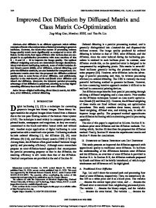
low-k film is desirable. The method should also be able to capture so-called ‘‘killer defects’’ which may significantly decrease the yield by allowing Cu or water to diffuse through the defect. One type of killer defects are isolated holes in the barrier, or pinholes, which have very low density 共several defects per square millimeter兲. Such defects might decrease the yield and they are difficult to find due to their low density. Several papers have been dedicated to investigation of the barrier performance on porous films.2,3 The physical idea of an evaluation of the barrier on porous low-k films by ellipsometric porosimetry 共EP兲 is similar to that of positron annihilation life time spectroscopy 共PALS兲.2 To evaluate a diffusion barrier, PALS examines the escape of positronium from a porous film to a vacuum through voids in the diffusion barrier. Evaluation by EP examines the adsorption/ desorption of toluene through the barrier. We have used EP for barrier characterization. EP is one of the most promising techniques for porosity and porous structure characterization of porous low-k films.4,5 This method is simple, informative, and can be used for in-line monitoring of low-k dielectrics. In this article, we propose a new EP application related to the evaluation of diffusion barriers deposited on top of low-k films. During the EP measurements, a barrier/film system is exposed to toluene vapor. Three possible cases are depicted in Fig. 1. If the barrier is fully continuous, then toluene cannot penetrate through it 关Fig. 1共a兲兴 and no changes are registered by EP. In the case of not fully dense barrier, toluene can penetrate through barrier pinholes and then it can be adsorbed by the low-k film. Such adsorp-
1071-1023Õ2003Õ21„1…Õ220Õ7Õ$19.00
©2003 American Vacuum Society
220
221
Shamiryan, Baklanov, and Maex: Diffusion barrier integrity evaluation
221
rous and nonporous barriers were identified as well as killer defects were visually observed. II. EXPERIMENT
FIG. 1. Schematic representation of the barrier/low-k stack in three cases: 共a兲 continuous barrier, 共b兲 partially porous barrier, and 共c兲 completely porous barrier.
tion changes the stack optical properties that are registered by EP. If barrier defect density is low, toluene will need time to fill the whole film by lateral diffusion underneath the barrier 关Fig. 1共b兲兴. In the case of high defect density, toluene should fill the film rather fast 关Fig. 1共c兲兴. This method could be used not only with porous films but also with any film which is able to adsorb toluene 共e.g., organic polymers兲. Though organic polymers are virtually nonporous, they can adsorb toluene that results in film swelling. Again, the swelling causes optical properties to change that, in turn, can be registered by EP. Killer defects can also be detected by EP. Although their density is too low to provide film filling with toluene, film optical properties will be changed locally beneath the barrier by trapped toluene. Such changes produce a color difference near a killer defect. Color spots can be easily counted optically or by using a light point defect detection tool. We suggest EP to be used for barrier continuity probing along with killer defect recognition. In this work, we show how the barrier integrity can be evaluated using EP in two cases: A physical vapor deposited 共PVD兲 TaN barrier on a porous hydrogen silsesquioxane 共HSSQ兲 film and an atomic layer deposited 共ALD兲 WCN barrier on an organic polymer low-k film. In both cases, poJVST B - Microelectronics and Nanometer Structures
Two different low-k films were capped with two different barriers. An ionized-PVD TaN barrier of various thickness was deposited on top of HSSQ-based porous low-k films. The porous films have mean pore diameter close to 5 nm and 50% porosity. The barrier film thickness was measured by spectroscopic ellipsometry 共SE兲. ALD WCN barrier was deposited on top of organic polymer low-k films using different number of cycles 共80, 100, and 120兲 resulting in various thicknesses. The barrier thickness was measured by SE. Both TaN/porous HSSQ and WCN/polymer samples with different barrier thicknesses were placed in an EP chamber which was slowly filled by adsorptive vapor 共toluene兲.5 Adsorption and condensation of toluene in the porous HSSQ film occurs at relative pressure P/ P 0 ⬍1 共where P 0 is a saturation pressure at room temperature兲 because of lower equilibrium vapor pressure above concave liquid meniscus formed in the pores. The condensed toluene (n⫽1.49 at ⫽633 nm) replaces air (n⫽1) in the pores that leads to a change in optical characteristic of the porous low-k film. Adsorption of toluene by organic polymer films can result in an increased refractive index and film swelling. In our case, an increase in thickness of about 20% was seen. The refractive index and thickness increases are measured by in situ SE 共SENTECH SE-801兲 as a function of toluene relative pressure. In the case of a porous HSSQ film, the changes of optical characteristics of the film during adsorption are used to calculate the volume of the condensed toluene 共open pore volume兲 and the pore size distribution. The principal scheme of the EP tool and more detailed description of the measurement and calculation procedures are described elsewhere.5 Optical microscope pictures have been taken on samples with visible color variation after an adsorption/desorption cycle. An isolated defect in a barrier becomes visible as a color change if toluene is trapped in the film around the defect. III. RESULTS AND DISCUSSION We have tested two types of diffusion barrier/low-k material systems: I-PVD Ta共N兲 barrier on porous HSSQ and ALD WCN barrier on organic polymer. In both cases, EP is able to detect defects in the barrier. A. Diffusion barrier on porous films
In the case of Ta共N兲/porous low-k film EP is capable of testing barrier integrity, but it is also able to measure optical properties and thickness of the barrier. 1. Barrier integrity tests
Toluene easily fills noncapped porous HSSQ changing film optical properties. Different optical properties manifest themselves in different values of the ellipsometric angles ⌿ and ⌬. A change of ⌿ and ⌬ angles during adsorption of
222
Shamiryan, Baklanov, and Maex: Diffusion barrier integrity evaluation
222
FIG. 2. Change of ⌿ and ⌬ angles during adsorption of toluene by porous HSSQ 共without a barrier兲. Toluene fills the porous film causing ⌿ and ⌬ to change. Pressure increase is indicated by an arrow.
toluene by porous HSSQ is a result of the change in film thickness and refractive index. This change is plotted in Fig. 2. Since the thickness change during the adsorption is very small 共less than 3% as measured by SE after the full adsorption at saturated toluene pressure兲, it is possible to calculate a theoretical curve using the refractive index as an independent variable and assuming the film thickness is constant. Good agreement between the experimental results and the calculated ones 共Fig. 2兲 means that toluene condensation inside the pores occurs without a significant change of the film thickness. This agreement allows the open pore volume, skeleton refractive index, and pore size distribution to be calculated.5 Very good agreement between the calculated curve and experimental data for noncapped film suggests that all pores are filled uniformly and are interconnected. When a porous film is capped with a barrier a theoretical model can be made taking into account optical properties of the barrier film. Again, the thickness of the porous film is assumed constant as well as the thickness of the barrier for the curve fitting. The optical constants of the barrier 共refractive index and extinction coefficient兲 are also assumed constant. The following arguments are used to justify the assumption of constant optical properties of the barrier. First, the barrier 共10 nm兲 is much thinner than the film 共500 nm兲. Second, the barrier porosity is only 10% 共as will be shown later兲. For a thicker barrier, the film porosity is negligible. Therefore, the barrier can only store a very little amount of toluene compared to the film and that should not greatly change the effective optical properties of the film/barrier system. At the same time, taking into account the variable refractive index of the barrier makes the calculation much more complicated. Thus, keeping optical properties of the barrier constant, only the refractive index of the porous film is assumed variable supposing toluene adsorption in the film. J. Vac. Sci. Technol. B, Vol. 21, No. 1, JanÕFeb 2003
FIG. 3. Change of ⌿ and ⌬ angles during adsorption of toluene by porous HSSQ capped with 共a兲 10 nm TaN or 共b兲 30 nm TaN. Toluene easily penetrates through the barriers causing ⌿ and ⌬ to change. Pressure increase is indicated by an arrow.
Very good agreement between the calculated and experimental data was obtained for low-k films capped by a 10 and 30 nm thick TaN barrier 共Fig. 3兲. This fact suggests that the TaN barriers contain a number of pinholes, which is high enough to allow toluene penetration through the barrier filling all the pores. A tail presented at the end of the adsorption is related to toluene adsorption on the top surface of the barrier and will be discussed later. Only a 60 nm thick TaN barrier showed disagreement between the calculated curve and experimental data 共Fig. 4兲. A specific signature in the experimental data allows us to conclude that toluene does not penetrate the barrier and no
223
Shamiryan, Baklanov, and Maex: Diffusion barrier integrity evaluation
FIG. 4. Change of ⌿ and ⌬ angles during adsorption of toluene by porous HSSQ capped with 60 nm TaN. Toluene cannot penetrate through the barriers, the ⌿ and ⌬ change is due to toluene condensation on the top surface of the barrier. Pressure increase is indicated by an arrow.
adsorption occurs. Disagreement between the experimental and calculated data at the end of adsorption 共in the form of a tail going off the calculated curve兲 can be attributed to the toluene adsorption at the surface of the TaN barrier. The top surface adsorption is observed only at pressure close to saturated whereas adsorption in pores occurs at lower pressure.6 When pressure is below saturation, toluene goes through the barrier and gets adsorbed in the pores. As pressure reaches saturation, toluene starts to get adsorbed on the top barrier surface. A decrease of ⌬ in association with almost constant ⌿ can be explained as a growth of a thin layer of solvent 共toluene in our case兲. The tail seems to increase with increasing TaN thickness, but this is due to a different ⌿/⌬ scale in different figures. A change in the tail is always approximately 2°. Note that the full change of ⌬ during adsorption is on the order of hundreds of degrees in the case of 10 nm Ta共N兲 关Fig. 3共a兲兴, tens of degrees in the case of 30 nm TaN 关Fig. 3共b兲兴, and less than 2° in the case of 60 nm Ta共N兲 共Fig. 4兲. Only the tail is seen at 60 nm barrier. From the data just presented, one can conclude that 60 nm TaN is thick enough to seal porous HSSQ with respect to toluene penetration. This conclusion is in agreement with the results reported for Ta and TaN barriers on porous organosilicates.2 2. Barrier characterization
Ellipsometric porosimetry can provide more information than just barrier integrity characterization. The barrier optical properties and thickness can also be determined, and an estimation of porosity and pore size in barrier can be made. To estimate barrier pore density we need to now how far toluene can diffuse in the porous film during the time between two ellipsometric measurements 共typically, 4 – 6 s兲. If the diffusion rate is high, then the porous film can be inJVST B - Microelectronics and Nanometer Structures
223
FIG. 5. Pore radius distributions for HSSQ without a barrier 共circles兲, with a 10 nm TaN barrier 共squares兲, and with a 30 nm TaN barrier 共triangles兲. The latter has smaller pores in the barrier.
stantly filled with toluene through a relatively small number of pinholes in the barrier. On the other hand, if the diffusion rate is low, the pinholes should be present in large amounts to allow instant film filling. To estimate the toluene diffusion rate in the porous film, we exposed the film without any barrier to the toluene vapor of constant pressure. Because at a constant pressure we saw no change in ⌿ and ⌬ with time, we can conclude that toluene fills the whole film 共500 nm兲 within the measuring interval or faster. Therefore, if the film is capped with a barrier and toluene fills the whole film instantly within the interval, we can conclude that the mean distance between the pores in the barrier is the same order of magnitude or less as the film thickness 关the case of a highly porous barrier is realized as shown in Fig. 1共c兲兴. The open porosity of the HSSQ-based films capped by 10 nm and 30 nm thick TaN films measured by EP was equal to the porosity of noncapped low-k film 共about 50%兲. Fast uniform pore filling by toluene was inferred by good fitting between the experimental data and a two-layer optical model with a variable refractive index of the bottom layer. Therefore, the pinholes concentration in the 10 and 30 nm thick barriers is high enough to allow filling of the whole film by the lateral diffusion of toluene beneath the barrier. Thus, as was just shown, the mean distance between the pores in barrier is the same order of magnitude as the film thickness 共500 nm兲. The size of the barrier pinholes can be evaluated from pore radius distribution 共PRD兲 measurements. The PRD of porous HSSQ films calculated from desorption curves are shown in Fig. 5. Generally, if pores are bottle shaped with a neck open to the surface, then the pore sizes calculated from desorption measurements reflect the neck radii.6 One can assume that pinholes in a barrier film act as bottle necks on the top of the pores of the low-k and, therefore, PRD will shift to smaller values. The distributions are identical for the non-
224
Shamiryan, Baklanov, and Maex: Diffusion barrier integrity evaluation
FIG. 6. Optical constants 共refractive indices—solid lines; extinction coefficients—dashed lines兲 of the Ta共N兲 barrier film as a function of its thickness as measured by spectroscopic ellipsometry—filled symbols and ellipsometric porosimetry—open symbols. Decreased barrier density 共porosity兲 is a reason for decreased n and k in the case of 10 nm film.
capped film and for the 10 nm TaN capped film. Thus, voids in the 10 nm thick TaN film are equal or larger than the pores in the low-k dielectric film. The PRD of HSSQ film with 30 nm Ta共N兲 cap is slightly shifted toward a smaller pore radii. It can be concluded that 30 nm thick TaN film is already starting to close the pore openings and, therefore, the barrier contains pinholes with sizes smaller than the pores in the low-k dielectric film. EP can also be used for the measurement of thickness and optical properties of porous barriers. Ellipsometric angles recorded during the adsorption of toluene by the porous film/ porous barrier stack were fitted to the theoretical curves as was described herein. In the ⌿/⌬ plane, the size, shape, and position of those curves strongly depend on the thickness and optical properties of the barrier film. The fitting of the calculated values to the measured ones was done by varying the refractive index, extinction coefficient, and thickness of the barrier film. The fitted values are compared to the values measured by conventional SE in Fig. 6 and Table I. All values measured by EP are in good agreement with those measured by SE. During SE measurements, theoretical TABLE I. Thickness of Ta共N兲 barrier deposited on porous HSSQ as measured by EP and SE. Nominal thickness is calculated from Ta共N兲 mean deposition rate. Ta共N兲 thickness 共nm兲
a
Nominal
Measured by SE
Measured by EP
10 30 60
13.2 28.8 60.5
12.5 27.0 Not applicablea
This value is impossible to measure because the barrier is impermeable for toluene.
J. Vac. Sci. Technol. B, Vol. 21, No. 1, JanÕFeb 2003
224
dispersions of ⌿ and ⌬ were fitted to the acquired values using the Cauchy representation of the optical layers. Both SE and EP measurements indicate a lower value for the refractive index and the extinction coefficient at the 10 nm barrier film thickness. Such lowered values could be attributed to a decreased density of the 10 nm barrier film. If part of the film is replaced by air with a refractive index n⫽1 and an extinction coefficient k⫽0, then the effective n and k will be lower. Such a mixture of two materials can be described as an optical layer by a Bruggeman model.7 In our case, the Bruggeman model was used to represent a mixture of Ta共N兲 and air. The optical characteristics of Ta共N兲 were fixed to the values obtained for thicker films 共30 and 60 nm兲 while only air percentage 共porosity, in other terms兲 was a variable in the model fitting. Such a fitting results in 10% air content. In other words, the 10 nm Ta共N兲 barrier film has about 10% porosity as deposited on porous HSSQ. Though the 30 nm barrier is also porous, it has n and k values close to those of the nonporous 60 nm barrier. It implies that the porosity of 30 nm barrier is not high enough to affect its optical properties 共in contrast to the case of the 10 nm barrier兲. The good agreement between the SE and EP results provides an additional method 共EP兲 for the evaluation of barrier optical properties and thickness. If a barrier is deposited on an organic polymer, similar tests can be carried out, as described in the following section. B. Diffusion barrier on organic polymers
EP can also be used for testing barrier integrity in the case of an organic polymer low-k film used as a substrate. Organic polymers can adsorb solvents 共toluene, in our case兲 due to the penetration of solvent into a polymer free volume. During adsorption, the thickness and optical characteristics of a polymer are changed. The thickness change is much larger 共20%兲 compared to porous glass 共⬍3%兲 and cannot be ignored. In contrast to the porous film case previously described, the theoretical calculation of ⌿ and ⌬ for organic polymers is more complex. This is because ⌿ and ⌬ are functions of two independent variables: refractive index and thickness. Nevertheless, changes of thickness and refractive index during toluene adsorption and desorption by a noncapped polymer film lead to a substantial variation in ⌿ and ⌬ values, as shown in Fig. 7. During adsorption, ⌿ and ⌬ move counterclockwise indicating a change in the optical properties of the film. During desorption, ellipsometric angles move back, not reaching, however, the initial point. This small irreversibility implies that a certain amount of toluene is still trapped inside the free volume pores of the polymer film. Theoretically, to remove the remaining toluene from the smallest 共⬍1 nm兲 pores, a relatively high vacuum (10⫺4 Torr) is needed.6 The vacuum of only 10⫺2 Torr was used in our experiments, which is not high enough to remove all toluene. The incomplete removal of toluene, however, does not affect barrier integrity tests. A good barrier should prevent toluene from penetrating and, therefore, ⌿ and ⌬
225
Shamiryan, Baklanov, and Maex: Diffusion barrier integrity evaluation
FIG. 7. ⌿/⌬ diagram obtained during adsorption 共open circles兲 and desorption 共filled ones兲 of toluene in an organic polymer film. Toluene fills the organic polymer film through the barrier causing a change of ⌿ and ⌬. Pressure increase 共adsorption兲 is indicated by the dashed arrow, pressure decrease 共desorption兲 is indicated by the dotted arrow.
from moving. In other words, if ⌿ and ⌬ move from the initial position during adsorption, then the barrier is not fully dense. The deposition of 3 nm WCN barrier by ALD on an organic polymer does not prevent toluene from penetrating into the polymer. Figure 8 shows almost the same substantial changes of ⌿ and ⌬ as Fig. 7, even though the polymer is now capped with a barrier. The only difference is a larger irreversibility 共⌿ and ⌬ do not return to the initial point兲 for the capped film, which can be attributed to more toluene trapping. Toluene could be trapped inside small pores requiring an additional vacuum to remove or toluene could diffuse below an impermeable barrier regions where pumping or
FIG. 8. ⌿/⌬ diagram obtained during adsorption 共open circles兲 and desorption 共filled ones兲 of toluene in an organic polymer film capped with a 3 nm WCN barrier. The barrier does not prevent toluene from penetration. Pressure increase 共adsorption兲 is indicated by the dashed arrow, pressure decrease 共desorption兲 is indicated by the dotted arrow. JVST B - Microelectronics and Nanometer Structures
225
FIG. 9. ⌿/⌬ diagram obtained during adsorption 共open circles兲 and desorption 共filled ones兲 of toluene in an organic polymer film capped with a 7 nm WCN barrier. The barrier mostly prevents toluene from penetration, but not completely. Pressure increase 共adsorption兲 is indicated by the dashed arrow, pressure decrease 共desorption兲 is indicated by the dotted arrow.
concentration gradient are ineffective leaving toluene trapped. Both cases, however, are not acceptable for a good diffusion barrier. The barrier of 7 nm WCN by ALD provides additional sealing, but this sealing is not complete. The change of ⌿ and ⌬ is much smaller 共Fig. 9兲 compared to a noncapped film 共Fig. 7兲, but significant. The ⌿/⌬ change is completely irreversible. During desorption, both ellipsometric angles continue moving in the same direction as during adsorption. We suggest the following explanation for this irreversibility. The barrier is mostly continuous but contains a number of pinholes. If density of the pinholes is rather low 关the mean distance between pinholes is larger than film thickness, as was discussed in the case of porous HSQ/Ta共N兲 barrier兴, then toluene penetrates through those pinholes and then fills the film by diffusion underneath the barrier 关as shown in Fig. 1共b兲兴. Due to the low pinhole density and limited diffusion rate, toluene can not fill the whole film instantly. Furthermore, toluene can not escape the film through the limited number of pinholes when the chamber is pumped down. Instead, toluene continues to diffuse beneath the barrier. That diffusion causes ⌿ and ⌬ to change in the same direction as during adsorption, indicating film filling by toluene. Again, an alternative explanation is the further decrease of barrier pore sizes. A higher and higher vacuum is needed to extract all toluene. In any case, toluene is still trapped in the organic polymer film after the adsorption/desorption cycle. The situation becomes different, however, if 10 nm WCN is deposited on top of an organic polymer film. Such a barrier is able to seal the organic polymer film with respect to toluene penetration. Ellipsometric angles do not change significantly during chamber filling with toluene 共Fig. 10兲. A small shift of ⌿ and ⌬ can be attributed to toluene condensation on top of the barrier. This fact means that the barrier is impermeable to toluene.
226
Shamiryan, Baklanov, and Maex: Diffusion barrier integrity evaluation
226
FIG. 10. ⌿/⌬ diagram obtained during adsorption 共open circles兲 and desorption 共filled ones兲 of toluene in an organic polymer film capped with a 10 nm WCN barrier. The barrier prevents toluene from penetration.
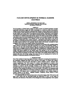
Barrier films determined to be sealed by EP may also contain some low-density killer defects. If the defects are far from each other 共in the order of mm兲, they cannot provide film filling by toluene in a reasonable time span. However, toluene can still penetrate through the isolated pinholes and then becomes trapped beneath the barrier. The trapped toluene locally changes the refractive index and thickness of the film. These changes manifest themselves as a color change near the defect, and can be observed visually by an optical microscope. Examples of such defects are shown in Fig. 11. In Fig. 11, panel 共a兲 shows ‘‘highlighted’’ barrier pinholes and panel 共b兲 shows cracks in the barrier 共obtained with nonoptimized deposition conditions兲. The cracked barrier film was a result of an ‘‘unlucky shot’’ during ALD development. We were able to find a poor quality film by a very fast and inexpensive way. The defects highlighted by adsorbed toluene can be counted manually or by any tool resolving light reflection difference 共e.g., a light point defect counter兲.
FIG. 11. Organic polymer low-k film capped with ALD barrier after exposure to toluene 共optical microscope pictures兲. The WCN barrier thickness is 10 nm in both cases; however, the barriers were obtained at different deposition conditions. Toluene captured beneath the barrier appears in black color. Pinholes 共a兲 or cracks 共b兲 in the barrier are made visible.
ACKNOWLEDGMENTS The authors would like to thank Zsolt To¨kei for Ta共N兲 barrier deposition, Ana Martin Hoyas and Jo¨rg Schuhmacher for WCN barrier deposition, and IMEC Pilot Line operators for sample preparation. Special thanks to Thomas Abell for fruitful discussions. W. W. Lee and P. S. Ho, Mater. Res. Bull. 22, 19 共1997兲. J.-N. Sun, D. W. Gidley, T. L. Dull, W. E. Frieze, A. F. Yee, E. T. Ryan, S. Lin, and J. Wetzel, J. Appl. Phys. 89, 5138 共2001兲. 3 E. T. Ryan, H.-M. Ho, W.-L. Wu, P. S. Ho, D. W. Gidley, and J. Drage, Proceedings of the International Interconnect Technology Conference, San Francisco, CA, 24 –26 May 1999, p. 187. 4 F. N. Dultsev and M. R. Baklanov, Electrochem. Solid-State Lett. 2, 192 共1999兲. 5 M. R. Baklanov, K. P. Mogilnikov, V. P. Polovinkin, and F. N. Dultsev, J. Vac. Sci. Technol. B 18, 1385 共2000兲. 6 S. J. Gregg and K. S. W. Sing, Adsorption, Surface Area, and Porosity, 2nd ed. 共Academic, New York, 1982兲, p. 195. 7 R. M. A. Azzam and N. M. Bashara, Ellipsometry and Polarized Light, 4th ed. 共Elsevier, Amsterdam, 1999兲. 1 2
IV. CONCLUSIONS We have shown that EP can be used for the evaluation of the integrity of diffusion barriers on top of low-k dielectrics, which can adsorb solvents 共e.g., porous glasses or organic polymers兲. Low-density killer defects in mostly continuous barriers can be visually identified and counted. If a barrier deposited on a porous film is not fully dense, then EP is able to determine the optical constants and thickness of the barrier, as well as estimate the structure of it.
J. Vac. Sci. Technol. B, Vol. 21, No. 1, JanÕFeb 2003