Driver for 14-Bit, 4.5Msps ADC Operates Over a Wide Gain Range Design Note 526 Guy Hoover Introduction The LTC ®2314-14 is a 14-bit, 4.5Msps, serial output ADC with an integrated high performance reference. The single-ended input of the LTC2314-14 is easy to drive and in many instances does not require a buffer. A driver, such as the LT6236 op amp, may be required for a signal that is small or has high output impedance. The LT6236 is a 215MHz gain bandwidth product, rail-to-rail output op amp/SAR ADC driver that features 1.1nV/√Hz input-referred noise voltage density and draws only 3.5mA of supply current with a typical offset of only 100µV. The LT6236 is a good choice for these applications because of its high bandwidth, low noise, low supply current and low offset.

ten depending on the value of R3, as shown in Table 1. Capacitor C1 and resistor R1 limit the input bandwidth to 68MHz. C1 also acts as a charge reservoir for the ADC sample-and-hold capacitor and helps to isolate the LT6236 from the transient that occurs at AIN when the ADC goes into sample mode. R1 is also used to help isolate the op amp from the ADC sampling transient. Table 1. Gain and Input Range Settings for Various Values of R3

The driver presented here is characterized over a range of gains, sampling frequencies and input frequencies to establish its application suitability.

R3 (Ω)

GAIN

AIN RANGE (V)


1

0 to 4.096

2k

2

0 to 2.048

499

5

0 to 0.8192

221

10

0 to 0.4096

L, LT, LTC, LTM, Linear Technology and the Linear logo are registered trademarks of Linear Technology Corporation. All other trademarks are the property of their respective owners.

Driver Operation Figure 1 shows a non-inverting amplifier driving the LTC2314-14. The driver has a gain between one and

C6 2.2µF

+

C3 0.1µF

R1 49.9Ω

V+

U2 LT6236 OUT – – V –3.6V

3.3V

C5 2.2µF

8V

AIN 0V TO 4.096V MAX

5V

C2 0.1µF

R2 2k

C4 22pF

C7 2.2µF 1 2 5 VDD REF OVDD

4 C1 47pF

U1 LTC2314-14

AIN

GND

CS SCK SDO

3 dn4gh F01

R3 *

*SEE TABLE 1

Figure 1. Single-Ended ADC Driver with Up to 0V to 4.096V Input Range 05/14/526

8

CS

7

SCK

6

SDO

Driver Performance The FFT in Figure 2 shows that with a gain of one this circuit has an SNR of 77dB and a THD of –84dB, with a sampling rate of 4.5Msps and a 600kHz input frequency. These numbers are close to the typical data sheet performance specifications for the LTC2314-14 alone, indicating that there is minimal performance degradation of the ADC when using this driver. Figure 3 shows SINAD performance vs sampling rate for gains of one through ten. The SINAD remains about the same for all gains at approximately 75dB to 76dB, with sampling rates from 1Msps to 4.5Msps, which is the maximum rated sampling frequency for this part. 0

fS = 4.5Msps fIN = 600kHz SNR = 77dB THD = 84dB AV = 1

–40

80

70 66 60

–60 –80

55

–100

50

–120 –140

0

0.6

1.2 1.8 FREQUENCY (MHz)

2.4

Figure 2. 16k-Point FFT for the Circuit of Figure 1 80 75 70 SINAD (dB)

AV = 1 AV = 2 AV = 5 AV = 10 0

500 1500 1000 2000 INPUT FREQUENCY (kHz)

2500 dn4gh F04

dn4gh F02

66 60 AV = 1 AV = 2 AV = 5 AV = 10

55 50

fS = 4.5Msps AIN = –1dBFS

75

SINAD (dB)

AMPLITUDE (dBFS)

–20

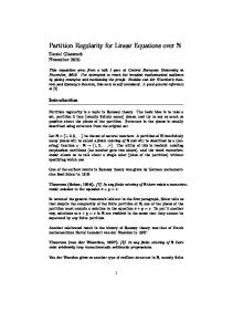
Figure 4 shows SINAD performance vs input frequency for gains of one through ten. The SINAD starts at 75dB to 76dB for an input frequency of 100kHz but falls as the input frequency and gain rises. For most applications a drop in SINAD of 3dB should be acceptable. At a gain of one, SINAD is reduced to 73dB beyond 2.2MHz. At a gain of two, SINAD is reduced to 73dB at approximately 1.2MHz. At a gain of five, SINAD is reduced to 73dB at approximately 600kHz. At a gain of ten, SINAD is reduced to 73dB at approximately 250kHz.

1

0

Figure 4. SINAD vs Input Frequency

Conclusion The LTC2314-14, 4.5Msps, 14-bit serial sampling ADC can be driven by the LT6236 rail-to-rail output, 215MHz low noise op amp/SAR ADC driver with gains ranging from one through ten, sample rates from 1Msps to 4.5Msps and input frequencies ranging from 100kHz to 2.2MHz. This driver circuit is appropriate for small or high output impedance signals. The results shown in Figures 3 and 4 can be used to assess the suitability of this driver for an application with a particular input signal bandwidth and gain.

fIN = 100kHz AIN = –1dBFS

3 2 4 SAMPLING RATE (Msps)

5 dn4gh F03

Figure 3. SINAD vs Sampling Rate

Data Sheet Download

www.linear.com/LTC2314-14

Linear Technology Corporation

For applications help, call (408) 432-1900 dn526f LT/AP 0514 111K • PRINTED IN THE USA

1630 McCarthy Blvd., Milpitas, CA 95035-7417 (408) 432-1900


FAX: (408) 434-0507 ● www.linear.com

 LINEAR TECHNOLOGY CORPORATION 2014

Driver for 14-Bit, 4.5Msps ADC Operates Over a ... - Linear Technology

Single-Ended ADC Driver with Up to 0V to 4.096V Input Range ... A driver, such as the LT6236 op amp, may be ... These numbers are close to the typical data.

385KB Sizes 1 Downloads 186 Views

Recommend Documents

Driver for 14-Bit, 4.5Msps ADC Operates Over a ... - Linear Technology
0 to 0.4096. L, LT, LTC, LTM, Linear Technology and the Linear logo are registered trademarks of Linear Technology Corporation. All other trademarks are the.

Monolithic Linear Battery Charger Operates from ... - Linear Technology
lead acid battery stack from a solar panel, though any combination of input and battery voltages are possible. The LTC4079's differential voltage regulation is.

Altera Stratix IV FPGA Interface for LTM9011 ADC ... - Linear Technology
I/O Architecture of Stratix IV FPGA. The Stratix GX device includes a built-in serializer/dese- rializer (SERDES) circuit that supports high speed LVDS interfaces at data rates of up to 1.6Gbps. Pin assignment is important in Stratix IV FPGA LVDS app

AN167: Buffered ADC Family Eliminates Signal ... - Linear Technology
Sep 20, 2017 - Active or Passive Notch Filters Do Not Degrade DC Parameters . ..... be stacked in series to double the input range and im- prove SNR by 3dB.

DN568 Reference Filter Increases 32-Bit ADC ... - Linear Technology
While reference noise has no effect at zero-scale, at full-scale any noise on the reference will be visible in the output code. This is why dynamic range ... voltage, produces a maximum error of 6µV which is relatively insignificant compared to the

AN167: Buffered ADC Family Eliminates Signal ... - Linear Technology
Sep 20, 2017 - at the ADC inputs to reduce RF interference that may have been picked up by the twisted pair. The analog inputs have no self-rectification mechanism that would convert. RF interference into a spurious DC level at the input pin, thus ma

DN1032 - DC Accurate Driver for the LTC2377-20 ... - Linear Technology
GND. GND. CNV. SCK. SDO. BUSY. 9. 13. 14. 11. 12. IN–. 3. 5. 9. 6. 6. 7. 4. 3. 3. 2. 2 ... a gain of minus one-half and drives the center of the .... call (408) 432-1900.

Low Power Filter, Headphone Driver Revisited - Linear Technology
Driver Revisited. Design Note ... 230µA, although data sheet supply maximum values suggest that ... ment headphone drivers is a rational enterprise, given the ...

DN556 - 3A, 1MHz Buck Mode LED Driver with ... - Linear Technology
Figure 3 shows measurement of the LED– voltage and the LED– ... call (408) 432-1900, Ext. 3801 ... all the way to ground, resulting in nearly the full 36V.

Low EMI LED Driver Features 2A, 40V, Integrated ... - Linear Technology
Introduction. The breadth of LED applications has grown to encom- pass everything from general lighting to automotive, industrial and test equipment, sign ...

Simple Battery Circuit Extends Power over ... - Linear Technology
in this application, to charge a single Li-Ion cell to its target termination voltage of 4.2V. PowerPath and Charger Circuit. In Figure 1, the LTC4055 provides triple ...

Robust High Voltage Over-The-Top Op Amps ... - Linear Technology
Design Note 533. Glen Brisebois .... considerations necessary when designing robustness into high ... the industrial system designer a precision solution for high ...

Robust High Voltage Over-The-Top Op Amps ... - Linear Technology
drive the output stage. As the ... Over-The-Top Input Stage on LT6015 Can Common Mode to 76V, Independent of Positive Supply Voltage. Q12. NPN ... the FET can turn hard on. This is ... down to 0.2V. Circuit gain is recovered in the second.

Operational Amplifier Selection Guide for ... - Linear Technology
Performance – Design Note 3. George Erdi. 10/87/3_conv. L, LT, LTC ... application requires large source resistors, the LT1028's relatively high current noise will ...

Linduino for Power System Management - Linear Technology
erences selection on the menu bar as shown in Figure 3. Finding Preferences ... libraries have a predefined main() that calls setup() and an infinite loop calling ...

LTC1560-1 - Linear Technology
Gain vs Frequency of the 1MHz and 500kHz. Figure 1. A Typical ... 6. 5. GND. VIN. GND. V–. VOUT. SHDN. V+. 0.5fC/fC. 5V. 3. 1k. 2. 4. VOUT. 7. LT®1360. 5V. – 5V. 8 ... DC offset of the 1/2 LT1364 plus its offset current times the 10k resistor ..

DN172 - Linear Technology
response is excellent, with less than 5μs recovery time from a ±400mA ... Data Sheet Download ... LTC1504 is the best solution where efficiency, especially.

DN518 - Linear Technology
possible to produce a low noise supply in this way, it requires careful ... typical switching regulator, and (3) the LTM8028 low ... call (408) 432-1900, Ext. 3747.

DN375 - Linear Technology
call (408) 432-1900. RF FREQUENCY (GHz) ... For ACPR/AltCPR, center the measurement band 5MHz/10MHz above the center of the highest carrier. To find ...

DN531 - Linear Technology
SiR664DP. M2. SiR664DP. L1. 5.6µH. WÜRTH 7443556560. M3. SiR422DP. M5. SiR422DP. D6. B360A. C19. 0.22µF. 25V. 0603. C20. 0.22µF. 25V. 0603. C21.

eterna1 - Linear Technology
Dec 16, 2015 - ... If testing encompasses measuring ETERNA1's output power or PSD, ..... go to: http://csrc.nist.gov/groups/STM/cavp/documents/aes/aesval.html.

Partition Regularity for Linear Equations over N
cp(pn) = cp(n) for all n ∈ N. Now we can prove that if a1x1 + ··· + anxn = 0 is PRN, then some non-empty subsum of the coefficients is 0. Proof of Rado's theorem (⇒). Suppose for a contradiction that the equation. E : a1x1 + ··· + anxn = 0

Optimal Linear Codes over Zm
Jun 22, 2011 - where Ai,j are matrices in Zpe−i+1 . Note that this has appeared in incorrect forms often in the literature. Here the rank is simply the number of ...