Evolution of a method for determination of transfer functions of certain passive electrical networks R1 VI
V’0
R2
V’’ 0
R3 +
C1p
C 2p
C 3p
V0
-
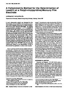
Figure 1: Low frequency Interconnect Model
K Radhakrishna Rao Abstract
The derivation of transfer functions of electrical networks is usually a tedious process involving the utilization of well known methods mesh and nodal analysis and the solution of matrix equations. Though numerical solutions can be obtained using computers, it is of limited use because of it's problem specific nature. Here, a method of finding analytical transfer functions using a combination of nodal and mesh analysis is illustrated using three practical examples. The method saves a tremendous amount of time and drastically reduces the probability of human error.
1 Introduction Understanding analog circuit design primarily invloves becoming familiar with passive RC and RLC networks. This is due to the fact that circuit essentially involves active elements embedded in a network of parasitics: resistors, inductors and node capacitors. Other important signal processing circuits which are made up of passive elements are attenuators, ADCs and R-2R ladder networks in DACs. Interconnects in present day VLSI can be approximated as passive RLC low pass structures from node to node. A few years ago, I was asked a question Can anyone inuitively guess the location of poles and zeros of a network transfer function? I reframed the problem as obtaining the characteristic equation of a network in a simple and straightforward manner. Once the characteristic equation has been obtained, then the roots of the polynomial will give the poles of the system. Understanding any transfer function or immittance function using the network becomes pretty simple thereafter!
2 Example 1 Let us start with a problem which, during my undergraduate studies, I had found difficult and time consuming to tackle. This is the RC phase shift oscillator shown in figure. This also is a low frequency interconnect model approximating a transmission line having two intermediate nodes between input and output. In this section the circuit in figure is solved using two traditional approaches and the new approach.
11
2 .1 Traditional approach Consider the network shown in figure. One traditional approach is the KVL which involves marking currents for each loop, writing the loop equations and then solving the matrix to finally obtain the currents using which all other parameters can be derived. Say, the transfer function, H(s) = Vo=Vi is desired. The matrix equation is as follows, I1
Vi
I2 I3
On solving the matrix equation,we obtain the current I3 with which we can determine the output voltage V0 in terms. The transfer function is, therefore,
V
I
V
V
To solve the matrix equation, one mathematical method is to diagonalize and hence simplify the matrix. Alternatively, we could have started with the node equations with KCL. However, one could choose to use a hybrid of both methods: use node voltages as well as loop currents successively to get a single set of equations. This method is simpler than the traditional one where we get terms like I 1 I2 as the net current inC1 and I 2 I3 as the net current in C2.
2.2 Alternate approach In this approach we start with the required dependent variable V and obtain all quantities (branch currents and node voltages), in terms of V . Therefore, the current in the last element across which the voltageV is taken is V . The same current flows through the series element and develops a voltage and therefore the last but one node voltage is V . This approach propagates towards all intermediate nodes upto the input node. Therefore, the next intermediate node has a voltage of V ( 1 + ) +V [ + (1 + )] ultimately giving us 1 + 1 + [ ( + (+ ( + + ([ H 2 ( + (+ + [ + 3 ( ([ + This method which is conventionally used in ladder networks integrates the technique of diagonalization into a network theorem based approach.
2.3 An intuitive approach
R1
Here, an attempt at writing the transfer function just by observation of the network, completely based on network approach. In the RC network considered earlier, if the capacitors are considered as open circuits ( = jw = 0), output voltage equals the input voltage and hence the coefficient of 0 in the denominator is one. R1
R2
R2
R3
+
V1
C1
C2
C 3p
V0
-
Subcircut # 3:Retaining only C 3p For the subcircuit 3, V
V [1
3
(
(
[
Thus, the coefficient of “ ” is the sum of all responses obtained from the individual subnetworks.
R3
+
V1
C1p
C 2p
(
V0
C 3p
-
Coefficient of
Removing all capacitors for the DC term
We know that, since the network is passive, the transfer function will be of the form
V V In order to find f(s), the network is broken down into a number of subnetworks. The method is illustrated below.
R1
2
Now, we construct the subnetworks using two capacitors at a time, assuming that the others are open- circuits. Here, the effect of all double integrations are taken into account. Hence, all combinations of double integrators in the circuit are considered. Here, only the node to node resistance is taken into account because we can visualize a double integrator as two single integrators cascaded. Thus, only the resistance from the output of one integrator to the input of the second integrator is taken into account.
Coefficient of
R1
When we consider only one capacitor at a time, the network behaves as low pass filter which acts as an integrator at high frequencies with charging current decided by the net series resistance connected to the capacitor from the input. The subnetworks are constructed by considering only one capacitor at a time and assuming others to be open-circuits. The voltages in a network can be visualized as being developed as a result of a number of integrations taking place in the circuit. The coefficient of accounts for all the single integrations occurring in the circuit. Hence each integrator ( combination) in the circuit is considered one at a time and the cumulative effect is added. R2
(
R2
R3
+
V1
C1p
C 2p
C3
V0
-
Subcircut # 1: Keeping C1p and C 2p For the subcircuit 1, V
VO 8R1S C1P 8R2S C2P
1
R1
V
2
R2
R3
+
V1
C1
C 3p
C 2p
R3
V0
-
Subcircut #2:Keeping C 2p and C 3p +
V1
C1p
C2
V0
C3
For the subcircuit 2, V
-
R1
Subcircut #1 Retaining only C1p For the subcircuit 1, V R1
1
V (1
(
R2
V1
C 2p
V0
C3
-
V [1
(
R2
R3
+
C 3p
C2
V0
-
Subcircut #3 Keeping C1p and C 3p For the subcircuit 3, V
VO S 2R1S C1P (R2S +R3S )C3P
3
As elucidated above, the coefficient of s2 is the sum of all terms obtained from the individual subnetworks
Subcircut # 2:Retaining only C 2p 2
(
(
C1p +
For the subcircuit 2, V
2
V1
R3
C1
V
2
(
[
(
(
(
(
12
Coefficient of
3
A similar logic as applied before can be used to easily see that the coefficient of s3 considers the triple integrations happening in the circuit. The subnetwork for this case is subcircuit 4 itself since three capacitors must be considered at a time. The coefficient contains only one term
Here again, each capacitor is considered and the resistance seen by it till the next node. Remember, resistances to be considered are from node to node since the triple integration is as a result of cascading three integrators, i.e capacitor-resistor combination. R1S
R2S
`series' between two nodes are considered to be an impedance Z and all `shunt' elements are taken as an admittance Y . Therefore,
Again, we note that the circuit is passive and hence the transfer function must be of the form 1+ratio of polynomials in s
In order to obtain the ratio,
the admittances are considered one at a time along with their corresponding
R3S
+
V1
C1P
C 3P V 0 -
C 2P
Figure 2: Interconnect model at high frequencies
1P
Subcircut #4: With all three C ,C2P and C3P
2.3.1 Transfer function of other nodes Now that we have obtained the transfer function , we can easily obtain the transfer functions at other nodes of the network. For instance, in order to find we have to find out . This can easily be done by the same method as described above, but this time the input signal is instead of . Hence, the part of the network from to is not considered and the same procedure is followed. It is evident that
subnetworks assuming that the other admittances are open circuits. Next, two admittances and their subnetworks are considered to write the product terms and so on. . . . This is a generic method to solve any given network with the limitation that it should be possible to reduce the network in the given form (a YZ ladder). The process is clearly illustrated in the equation below
1+ratio of polynomials in s 3
ratio of polynomials Following the method described above we obtain,
3
3
3
3
3
3
3
three
4 Example 3 and thus. . .
D( ( Wherever an input voltage source appears in series with a network element or an input current source in shunt with an element, the D ( ( of the transfer function of any current or voltage remains unchanged. This D ( ( is specific to a given network and is known as the characteristic equation of the network.
The circuit shown in figure 3 depicts a resistance ladder commonly encountered in DAC circuits. Actual DAC circuits are comprised of R-2R ladders. Nevertheless, the resistances here are assumed to have different values to assess the sensitivity of the circuit to parameter variations that may be caused due to temperature variations, defects, high tolerances of the resistors, etc. Hence it becomes necessary to evaluate the transfer function at different nodes. The transfer function can be found in the similar
2. Example 2 Here, we seek to obtain the transfer function of the circuit shown in figure 2. This circuit models interconnects at high frequencies when the inductive effects become considerably large. In order to find the transfer function of this circuit, a more generic approach is used. All network elements that come in
13
Figure 3
manner i.e, by taking one admittance at a time and it's subnetwork, two admittances and so on. . . The transfer function is displayed below
National Conference on LowPower Embedded Systems C.P. Ravikumar Texas Instruments, India
In a DAC, it is important to find the transfer function of every node. Hence, following the method described previously, we obtain –
5 Conclusion I'm sure you can try this method to impress your peers and teachers alike! I'm grateful to Mr. Ravi Karnad of TI, Bangalore and Mr. Ritesh Bhat of third year, NITK Surathkal, for the several discussions and revisions I had with them and for the emergence of the final manuscript in the present form.
References [1]
[2]
Embedded systems surround us today. We see them in medical equipment for health monitoring, in weighing machines, in portable equipment for communication and infotainment, in cars … Even the low-end cars have tens of micro controllers and a great deal of analog electronics embedded into them. Whether they depend on batteries or run off the mains power, it makes economical and ecological sense to reduce the power consumption of embedded electronics. Texas Instruments, Cranes Software, and VTU jointly organized an event in Bangalore recently to provide an exposure of the technology used in low-power embedded systems to students and faculty. The two-day national conference on Low Power Embedded Systems held in Bangalore (JSS ATE) concluded successfully on Feb 20, 2009. The conference attracted over 250 participants from different organizations across India. Prof. A.N.N. Murthy, Principal of JSS ATE, welcomed everyone and explained the goals of the two-day conference. The Honorable Vice Chancellor of VTU, Prof. H.P. Khincha, delivered the inaugural talk and emphasized the importance of embedded systems. Ramesh Ramamritham (TI), Ashfaq Ibrahim (Cranes Software) spoke about the relevance of low-power embedded systems and the need to study them in the curriculum.
Basil L . Cochrun and Arvin Grabel, A method for the determination of the transfer functions of electronic circuits, IEEE Trans. Circuit Theory, vol. CT-20, No. 1, January 1973 M.E. Van Valkenburg, Network Analysis, Third Edition, Prentice-Hall India, 2007
Inauguration of the National Conference on Low Power Embedded Systems. Dr. T.N. Nagabhushan, Ramesh Ramamritham, Prof. A.N.N. Murthy, Prof. H.P. Khincha, Prof. B.G. Sangama, Ashfaq Ibrahim, C.P. Ravikumar
Are you on UniTI mailing list? This is a mailing list exclusively for faculty members from India. On this mailing list, we publicize any technical events (seminars, workshops, conferences, train-thetrainer programs) that are held in India with collaboration from Texas Instruments. In order to become a member, please send a note to C.P. Ravikumar (
[email protected])
The Vice Chancellor (VTU) spoke about the efforts that are under way to establish an "Embedded System Valley" in India. He released the proceedings of the conference and encouraged the students and faculty to make best use of the learning opportunity. Prof. T.N. Nagabhushan of VTU Learning Center spoke about the topic of embedded software design. C.P. Ravikumar conveyed the vote of thanks. Special thanks are due to the management of JSS ATE, the team from Cranes Software. The conference included a full-day tutorial on the MSP430 microcontroller, invited paper presentations, student paper presentations, and a panel discussion.
14