USO0RE43 994E
(19) United States (12) Reissued Patent Taylor (54)
(10) Patent Number: US RE43,994 E (45) Date of Reissued Patent: Feb. 12, 2013
FLEXIBLE MATERIAL
(56)
References Cited
(75) Inventor: David Stirling Taylor, Accrington (GB) 2,751,609 2,785,739 3,020,186 3,137,746 3,285,768 3,285,800 3,293,671 3,305,423 3,404,406 3,441,638
(73) Assignee: Stirling Mouldings Limited (GB)
(21) App1.No.: 12/642,550 (22) Filed:
Dec. 18, 2009 Related US. Patent Documents
Reissue of:
6,743,325
Issued:
3,471,865 3,512,190 3,515,625 3,679,263
Jun. 1, 2004
Appl. No.:
10/030,782
PCT Filed:
Jul. 13, 2000
PCT No.:
PCT/GB00/02687
§ 371 (0)0), (2), (4) Date:
Apr. 23, 2002
A A A A
3/1957 2/1962 6/1964 11/1966 11/1966 12/1966 2/1967 10/1968 4/1969 9/1969
10/1969 5/1970 6/1970 7/1972
McGregor, Jr. et al. Lawrence Seymour et al. Habib Bartellet a1. Grif?n Masson Balliet Patchellet a1. Edelson ............................ .. 2/22
Molitoris Buff Sedlak et a1. Cadiou
(Continued) FOREIGN PATENT DOCUMENTS
PCT Pub. No.: WO01/03530 PCT Pub. Date: Jan. 18, 2001
DE DE
Continuation of application No. 11/269,919, ?led on Nov. 8, 2005, now Pat. No. Re. 41,346.
3641609 Cl 9102039 U
2/1988 5/1991
(Continued)
US. Applications:
(30)
A A A A A A A A A
3,465,364 A *
(64) Patent No.:
(63)
U.S. PATENT DOCUMENTS A 6/1956 Oesterling et al.
OTHER PUBLICATIONS Sarna Xiro GmbH, EC Safety Data Sheet, Jan. 16, 2001, 5 pages.
(Continued)
Foreign Application Priority Data
Primary Examiner * Mark A Osele Jul. 13, 1999
(GB) .................................... .. 9916291
(74) Attorney, Agent, or Firm * Fitch, Even, Tabin &
Sep. 16, 1999
(GB) .................................... .. 9921804
Flannery, LLP
(51)
Int. Cl. B32B 38/04
(57) (2006.01)
(52)
US. Cl. .... .. 428/304.4; 2/16; 2/22; 2/456; 156/265; 156/300
(58)
Field of Classi?cation Search ............ .. 2/455, 456,
2/2.15, 2.16, 16, 20, 22, 23, 24; 156/301, 156/560, 308.2, 251, 256, 259, 264, 265, 156/271, 299, 300, 512, 515, 561, 583.1; 428/141, 304.4 See application ?le for complete search history.
ABSTRACT
A ?exible material includes a plurality of separate resilient elements joined to a ?exible, resiliently stretchable substrate. Such a material is suitable for providing protective war for human and animal bodies. Preferably, the elements includes a foam material such as a closed cell polyethylene foam and the substrate includes a knitted fabric. In an advantageous embodiment, a second ?exible substrate is bonded over the
elements to sandwich them between the two layers of sub strate.
29 Claims, 3 Drawing Sheets
US RE43,994 E Page 2 2004/0171321 A1 2010/0272969 A1 2010/0285299 A1
U.S. PATENT DOCUMENTS
3,746,605 3,775,526 3,867,238 3,911,185 3,914,487 3,922,329 4,023,213 4,126,177 4,136,222 4,138,283 4,197,342 4,255,552 4,272,850 4,276,341 4,415,622 4,482,592 4,485,919 4,507,801 4,512,037 4,534,354 4,538,301 4,581,186 4,631,221 4,646,367 4,692,199 4,713,854 4,718,214 4,730,761 4,734,306 4,756,026 4,809,374 4,856,393 4,859,274 4,867,826 4,991,230 5,052,053 5,129,295 5,160,785 5,168,576 5,188,879 5,232,762 5,322,730 5,353,455 5,360,653 5,405,665 5,452,477 5,534,208 5,551,082 5,594,954 5,689,836 5,727,252 5,780,147 5,823,981 5,938,878 6,070,267 6,070,273 6,085,353 6,093,468 6,167,790 6,235,661 6,253,376 6,295,654 6,301,722 6,317,888 6,374,409 6,485,448 6,584,616 6,654,962 6,743,325 6,820,279 6,841,022 6,851,124 6,968,573 6,969,548 B1* 7,007,356 B2 2002/0004001 A1
7/1973 11/1973 2/1975 10/1975 10/1975 11/1975 5/1977 11/1978 1/1979 2/1979 4/1980 3/1981 6/1981 6/1981 11/1983 11/1984 12/1984 4/1985 4/1985 8/1985 9/1985 4/1986 12/1986 3/1987 9/1987 12/1987 1/1988 3/1988 3/1988 7/1988 3/1989 8/1989 8/1989 9/1989 2/1991 10/1991 7/1992 11/1992 12/1992 2/1993 8/1993 6/1994 10/1994
Dillon et al. Gilmore Johannsen
9/2004 Plant
10/2010 Taylor 11/2010 Taylor
FOREIGN PATENT DOCUMENTS
Wright, Jr.
DE DE DE EP FR FR GB GB GB JP JP JP JP JP WO WO WO WO WO WO WO WO
AZoulay Kim et al. Rovani Smith et al. Jonnes Hanusa Bethe
Schollenberger et al. Rule Tanaka Kamat Kramer Sandel
Kavanagh et al. Vacanti Bonner, Jr. et al. SawatZki et al. Larson Disselbeck et al. El Hassen KoZlowski et al. Graebe
Waggoner Spano
4341722 19640263 202006013732 1 369 149 2581348 2635650 800474 832101 2 304 539 1-316235 2508289 9300510 10043007 10337797 97/33493 97/36740 01/03530 01/15892 02/16124 02/081202 2006/036072 2006/088734
A1 A1 U A1 A1 A1 A A A A Y2 A A A A1 A1 A1 A1 A1 A1 A1 A1
6/1994 4/1998 2/2007 12/2003 11/1986 3/1990 8/1958 4/1960 3/1997 12/1989 8/1996 11/1997 2/1998 12/1998 9/1997 10/1997 1/2001 3/2001 2/2002 10/2002 4/2006 8/2006
OTHER PUBLICATIONS
Lassiter
Jeff Hopkins, “Advances, Advantages, and Techniques of Hot Melt Adhesives”, Journal of Industrial Textiles, (1993), pp. 5-13.
Pierce, Jr. SavieZ Braddon Marvel
John Halbmaier, “Overview of Hot Melt Adhesives Application
Krent et al. Hill et al.
Equipment for Coating and Laminating Full-Width Fabric s”, Journal of Industrial Textiles, (1992), pp. 301-310. Walter Fung, “Coated and Laminated Textiles”, (2002), pp. 114-133. SAE Speci?cation AMS 3698A, (Jul. 1, 1987), 13 pages. SAE Speci?cation AMS 3698B, (Jan. 1, 1993), 1 page. Memorandum in Support of Plaintiffs’ Motion for Preliminary Injunction, ?led May 28, 2009, and Exhibits 1-10 thereto (Public
Ruby
(Redacted) Version).
Ou
CorrectedVersion of Exhibit 2, Part 1 to the Memorandum in Support of Plaintiffs’ Motion for Preliminary Injunction, ?led Jun. 5, 2009. Plaintiffs’ Claim Construction Memorandum, ?led Jun. 15, 2009,
Wayte Vacanti Peart et al. Geffros et al.
Davidson, Jr.
Loving et al.
Ackley Shukushima et al. Mann 7/1996 Barr et al. 9/1996 Stewart et al. 1/1997 Huang 11/1997 Fee et al. 3/1998 Oetting et al. 7/1998 Sugahara et al. 10/1998 Grim et al. 8/1999 Hurley et al. 6/2000 McKewin 6/2000 Sgro 7/2000 van der Sleesen 7/2000 Toms et al. 1/2001 Bambara et al. 5/2001 Khanamirian 7/2001 Ritter 10/2001 Farrell 10/2001 Nickerson et al. 11/2001 McFarlane 4/2002 Galy 11/2002 Lamping et al. 7/2003 Godshaw et al. 12/2003 DeMott 6/2004 Taylor 11/2004 Lesosky 1/2005 Tsukago shi et al. 2/2005 Munoz et al. 11/2005 Silver 11/2005 Gold?ne ..................... .. 3/2006 Cudney et al. 1/2002 Marx et al.
and Exhibits 1-6 thereto.
Responsive Claim Construction Brief of Defendant Nike USA, Inc., ?led Jul. 13, 2009 (Redacted). Declaration of Alyson G. Barker in support of Nike USA’s Respon sive Claim Construction, ?led Jul. 13, 2009, and Exhibit A thereto. Plaintiffs’ Rebuttal Memorandum on Claim Construction, ?led Jul.
13, 2009, and Exhibits 1-5 thereto. Joint Claim Construction Chart and Status Report, ?led Sep. 1, 2009.
Memorandum Opinion and Order Construing Disputed Claim Terms, entered Sep. 17, 2009, Honorable James F. Holderman.
Watson, Chris, “Hot Melt Coating Methods: The More They Change the More They Stay the Same,” 1996 Hot Melt Symposium Tappi Proceedings (1996), pp. 1-5. Hoffman, Edward G., “Jig and Fixture Design” (1980), pp. 205-219. Bender, Rene J., “Handbook of Foamed Plastics” (1965), pp. 285 293.
Walker, John R., “Machining FundamentalsiFrom Basic to Applied Techniques” (1993), pp. 502-503. Lascoe, O.D., “Handbook of Fabrication Processes” (1988), p. 215. Petrie, Edward M., “Handbook ofAdhesives and Sealants” (2000), p. 308.
Roff, W.J., et al., “Handbook of Common PolymersiFibres, Films, Plastics and Rubbers” (1971), p. 456.
428/159
“Protecting Your Assets,” World Sports Activewear, vol. 2, Issue 3 (Autumn 1996), pp. 24-28. “ESC Steel Rule Dies,” available at http://escutters.co.uld#/laser ?at-bed/4525904364 (last visited Mar. 30, 2010), 1 page. “Hot Melt Adhesives Technology Review,” Paci?c Northwest Pollu tion Prevention Resource Center (Sep. 1988), available at http://pprc. org/pubs/techreviews/hotrnelt.hmintro.htrnl (last visited Mar. 30, 2010), 2 pages.
US RE43,994 E Page 3
Defendant Nike USA, Inc.’s Response to Plaintiffs’ Sur-reply on
McDavid’s Memorandum in Support of Motion for Summary Judg ment of No Invalidity of US Patent No. RE42,689 dated Apr. 19, 2012iMcDavid Knee Guard, Inc. v. Nike USA, Inc., Civil Action
Nike’s Motion for Summary Judgment of Invalidity dated Sep. 6,
No. 08-CV-6584.
2012, McDavidKnee Guard, Inc. v. Nike USA, Inc., CivilNo. 08-CV 6584, 15 pages.
McDavid’s Rule 56(a) Statement regarding Motion for Summary Judgment of No Invalidity US Patent No. RE42,689 dated Apr. 19,
Memorandum Opinion and Order dated Sep. 19, 2012, McDavid
2012iMcDavid Knee Guard, Inc. v. Nike USA, Inc., Civil Action No. 08-CV-6584.
US. Appl. No. 12/642,522, ?led Dec. 18, 2009, Applicant: David
Stirling Taylor.
Knee Guard, Inc. v. Nike USA, Inc., Civil No. 08-CV-6584, 27 pages.
Motion by Nike USA, Inc. to amend/correct Non-Infringement and Invalidity Contentions Pursuant to Local Patent Rule 3.4 dated Feb. 24, 2012iMcDavid Knee Guard, Inc. v. Nike USA, Inc., Civil Action No. 08-CV-6584.
McDavid’s Motion for Summary Judgment of No Invalidity of US Patent No. RE42,689 Under 35 USC 112 dated Apr. 19, 2012* McDavid Knee Guard, Inc. v. Nike USA, Inc., Civil Action No. 08-CV-6584.
Response by McDavid Knee Guard, Inc. in Opposition to Motion by
McDavid’s Memorandum in Support of Motion for Summary Judg
Nike USA, Inc. to amend/ correct Non-Infringement and Invalidity
ment of No Invalidity of US Patent No. RE42,689 Under 35 USC 1 12 dated Apr. 19, 2012iMcDavid Knee Guard, Inc. v. Nike USA, Inc., Civil Action No. 08-CV-6584. McDavid’s Statement of Material Facts Pursuant to Local Rule 56.1 in Support of Plaintiff’ s Motion for Summary Judgment of No Inval
Contentions Pursuant to Local Patent Rule 3.4 dated Feb. 29, 2012* McDavid Knee Guard, Inc. v. Nike USA, Inc., Civil Action No. 08-CV-6584.
Reply by McDavid Knee Guard, Inc., Stirling Mouldings Limited to response in opposition to motion Reply in Support of Plaintiffs’ Motion for Summary Judgment of Infringement of US. Reissue Patent RE42,689 dated Feb. 29, 20 1 2iMcDavid Knee Guard, Inc. v. Nike USA, Inc., Civil Action No. 08-CV-6584. Response to Defendants Additional Statement of Facts by McDavid
Knee Guard, Inc., Stirling Mouldings Limited dated Feb. 29, 2012* McDavid Knee Guard, Inc. v. Nike USA, Inc., Civil Action No. 08-CV-6584.
Reply by Nike USA, Inc. In Support of its Motion to Amend Non Infringement and Invalidity Contentions dated Feb. 29, 2012* McDavid Knee Guard, Inc. v. Nike USA, Inc., Civil Action No. 08-CV-6584. Minute Entry before Honorable James F. Holderman on Mar. 1, 2012
authorizing supplementation of invalidity contentionsiMcDavid Knee Guard, Inc. v. Nike USA, Inc., Civil Action No. 08-CV-6584. Minute Entry before Honorable James F. Holderman on Mar. 5, 2012
idity ofUS Patent No. RE42,689 Under 35 USC 112 dated Apr. 19, 2012iMcDavid Knee Guard, Inc. v. Nike USA, Inc., Civil Action No. 08-CV-6584.
Declaration of Glenn L. Beall regarding Motion for Summary Judg ment in Support of Plaintiff’ s Motion for Summary Judgment of No Invalidity of US Patent No. RE42,689 Under 35 USC 1 12 dated Apr. 19, 2012iMcDavid Knee Guard, Inc. v. Nike USA, Inc., CivilAction No. 08-CV-6584. McDavid’s Motion for Claim Construction of US Patent No.
RE42,689 dated Apr. 19, 2012iMcDavid Knee Guard, Inc. v. Nike USA, Inc., Civil Action No. 08-CV-6584. McDavid’s Memorandum in Support of Motion for Miscellaneous Relief for Claim Construction of US Patent No. RE42,689 dated Apr. 19, 2012iMcDavid Knee Guard, Inc. v. Nike USA, Inc., CivilAction No. 08-CV-6584.
denying Plaintiffs Motion for Summary JudgmentiMcDavid Knee
Declaration of SchletZbaum regarding Motion for Summary Judg ment of Invalidity dated Apr. 19, 2012iMcDavid Knee Guard, Inc.
Guard, Inc. v. Nike USA, Inc., Civil Action No. 08-CV-6584.
v. Nike USA, Inc., Civil Action No. 08-CV-6584.
Memorandum Opinion and Order signed by the Honorable James F.
Declaration of SchletZbaum regarding Motion for Summary Judg ment of Non-Infringement dated Apr. 19, 2012iMcDavid Knee
Holderman on Mar. 5, 2012 denying Plaintiff’ s Motion for Summary JudgmentiMcDavid Knee Guard, Inc. v. Nike USA, Inc., Civil Action No. 08-CV-6584.
Nike’s Invalidity Contention Charts 1-21 (non-con?dential attach ments to con?dential Supplemental Invalidity Contentions)i McDavid Knee Guard, Inc. v. Nike USA, Inc., Civil Action No.
08-CV-6584, (No date provided). McDavid’s Reply to Defendant’s Supplemental Invalidity Conten tions regarding U.S. Reissue Patent 42,689 dated Apr. 5, 2012* McDavid Knee Guard, Inc. v. Nike USA, Inc., Civil Action No. 08-CV-6584.
Nike’s Motion for Summary Judgment of Invalidity dated Apr. 19, 2012iMcDavid Knee Guard, Inc. v. Nike USA, Inc., Civil Action No. 08-CV-6584.
Nike’s Memorandum in Support of Motion for Summary Judgment of Invalidity dated Apr. 19, 20 12iMcDavid Knee Guard, Inc. v. Nike USA, Inc., Civil Action No. 08-CV-6584. Nike’s Statements of Undisputed Material Facts Pursuant to Local Rule 56.1 in Support of Defendant’s Motion for Summary Judgment of Invalidity dated Apr. 19, 20 12iMcDavid Knee Guard, Inc. v. Nike USA, Inc., Civil Action No. 08-CV-6584.
Nike’s Motion for Summary Judgment of Non-Infringement dated Apr. 19, 2012iMcDavid Knee Guard, Inc. v. Nike USA, Inc., Civil Action No. 08-CV-6584.
Nike’s Memorandum and Points of Authorities in Support of Defen
dant’s Motion for Summary Judgment of Non-Infringement dated Apr. 19, 2012iMcDavid Knee Guard, Inc. v. Nike USA, Inc., Civil Action No. 08-CV-658. Nike’s Statement of Undisputed Material Facts Pursuant to Local
Rule 56.1 in Support of Defendant’s Motion for Summary Judgment of Non-Infringement dated Apr. 19, 2012iMcDavid Knee Guard, Inc. v. Nike USA, Inc., Civil Action No. 08-CV-6584.
Guard, Inc. v. Nike USA, Inc., Civil Action No. 08-CV-6584. Nike’s Motion to Strike Plaintiffs’ Reply to Nike’s Non-Infringe ment Contentions dated Apr. 19, 2012iMcDavid Knee Guard, Inc. v. Nike USA, Inc., Civil Action No. 08-CV-6584.
Declaration of Jaren E. Hedman regarding Motion for Summary Judgment of No Invalidity of US Patent No. RE42,689 Under 3 5 USC 251 dated Apr. 19, 2012iMcDavid Knee Guard, Inc. v. Nike USA, Inc., Civil Action No. 08-CV-6584.
Declaration of Henkelmann regarding Motion for Summary Judg ment in Support of Plaintiffs’ Motion for Summary Judgment of No Invalidity of US Patent No. RE42,689 Under 35 USC 1 12 dated Apr. 19, 2012iMcDavid Knee Guard, Inc. v. Nike USA, Inc., CivilAction No. 08-CV-6584. Corrected Plaintiffs’ Statement of Material Facts Pursuant to Local
Rule 56.1 in Support of Plaintiffs’ Motion for Summary Judgment of No Invalidity ofU.S. Patent No. RE42,689 Under 35 USC 112 dated Apr. 19, 2012iMcDavid Knee Guard, Inc. v. Nike USA, Inc., Civil Action No. 08-CV-6584. Plaintiffs’ Motion for Leave to File Fourth Amended Complaint dated Jun. 7, 2012iMcDavid Knee Guard, Inc. v. Nike USA, Inc., Civil No. 08-CV-6584. Plaintiffs’ Notice of Motion for presentment of Motion for Leave to File Fourth Amended Complaint dated Jun. 7, 20 12iMcDavid Knee Guard, Inc. v. Nike USA, Inc., Civil No. 08-CV-6584. Minute Entry Order granting Plaintiffs’ Notice of Motion for pre sentment of Motion for Leave to File Fourth Amended Complaint dated Jun. 11, 2012iMcDavid Knee Guard, Inc. v. Nike USA, Inc., Civil No. 08-CV-6584. Plaintiffs’ Fourth Amended Complaint dated Jun. 14, 2012* McDavid Knee Guard, Inc. v. Nike USA, Inc., Civil No. 08-CV-6584.
Redacted Highly Con?dential Expert Report of Glenn L. Beall Regarding the Validity of US. Reissued Patent No. RE42,689 dated
McDavid’s Motion for Summary Judgment of No Invalidity of US Patent No. RE42,689 dated Apr. 19, 2012iMcDavid Knee Guard,
Jun. 19, 2012iMcDavid Knee Guard, Inc. v. Nike USA, Inc., Civil
Inc. v. Nike USA, Inc., Civil Action No. 08-CV-6584.
No. 08-CV-6584.
US RE43,994 E Page 4
Fourth Amended Complaint, ?led Jul. 2, 2012, document #505, 14
Nike USA Inc.’s Reply Brief in Support of Motion for Partial Dis missal of Plaintiffs’ Third Amended Complaint dated Nov. 10,
pages. Plaintiffs’ Answer to Defendant Nike’s Counterclaims in Answer to
201 liMcDavid Knee Guard, Inc. v. Nike USA, Inc., Civil No. 08-CV-6584.
Plaintiffs’ Fourth Amended Complaint, ?led Jul. 26, 2012, document #506, 5 pages.
Opinion dated Oct. 19, 201 1 regarding Motion for Reconsideration of Order Granting Nike’s Motion for Summary judgment of Non-in
Plaintiffs’ Opposition to Nike USA Inc. ’ s Motion for Summary Judg
fringement of claim I of the ’346 Patent Under the Doctrine of EquivalentsiMcDavidKnee Guard, Inc. v. Nike USA, Inc., Civil No.
Defendant Nike USA Inc.’ s Answer and Counterclaims to Plaintiffs’
ment of Invalidity, ?led Jul. 26, 2012, document #507, 22 pages. Plaintiffs’ Response to Defendant Nike USA, Inc.’s Statement of Undisputed Materials Facts Pursuant to Local Rule 56 .l in Support of Defendant’s Motion for Summary Judgment of Invalidity and Plain tiffs’ Additional Undisputed Facts That Support Denial of Summary Judgment, ?led Jul. 26, 2012, document #509, 23 pages. Declaration of Jared E. Hedman in Support of Plaintiffs’ Opposition to Nike’s Motion for Summary Judgment of Invalidity, ?led Jul. 26, 2012, document #510, 137 pages. Declaration of Glenn L. Beall in Support of Plaintiffs’ Opposition to Nike’s Motion for Summary Judgment of Invalidity, ?led Jul. 26, 2012, document #5 l l, 14 pages. Defendant Nike USA Inc.’s Reply in Support of Motion for Sum
mary Judgment of Invalidity, ?led Aug. 16, 2012, document #514, 21 pages. Defendant Nike USA Inc.’s Response to Plaintiffs’ Additional State
ments of Undisputed Facts Pursuant to Local Rule 56. l, ?ledAug. 16, 2012, document #515, 18 pages. Declaration of Ryan J. SchletZbaum in Support of Nike’s Reply in Support of Nike’s Reply in Support of Nike’s Motion for Summary
Judgement of Invalidity, ?led Aug. 16, 2012, document #516, 103
08-CV-6584.
Plaintiff’ s Opening Claim Construction Memorandum dated Nov. 5, 20l0iMcDavid Knee Guard, Inc. v. Nike USA, Inc., Civil No. 08-CV-6584.
Declaration of Alyson G. Barker in Support of Defendant Nike USA, Inc.’s Responsive Claim Construction Brief re Reissue Patent dated Nov. 19, 20l0iMcDavid Knee Guard, Inc. v. Nike USA, Inc., Civil No. 08-CV-6584.
Plaintiffs’ Response to Defendant Nike’s Opening Claim Construc tion Brief dated Nov. 19, 20l0iMcDavid Knee Guard, Inc. v. Nike USA, Inc., Civil No. 08-CV-6584.
Reply by Plaintiffs McDavid Knee Guard, Inc., Stirling Mouldings Limited to Nike’s Responsive Claim Construction Brief dated Dec. 10, 20l0iMcDavid Knee Guard, Inc. v. Nike USA, Inc., CivilAction No. 08-CV-6584.
Memorandum Opinion and Order denying motion for preliminary injunction signed by the Honorable James F. Holderman on Jan. 14, 20l0iMcDavid Knee Guard, Inc. v. Nike USA, Inc., Civil. No. 08-CV-6584. Mandate of USCA Federal Circuit dated Dec. 9, 2010 regarding
pages.
Notice of Appeal related to denial of motion for preliminary injunc
Defendant Nike USA Inc.’s Initial Invalidity Contentions for US. Reissue Patent No. RE43 ,441, 58 pages. Plaintiff’ s Surreply in Opposition to Nike’s Motion for Summary
tion on Dec. 15, 20l0iMcDavid Knee Guard, Inc. v. Nike USA, Inc., Civil No. 08-CV-6584. Plaintiffs’ Brief Regarding the Patent Of?ce’s Consideration of the
Judgment of Invalidity, McDavid Knee Guard, Inc. v. Nike USA, Inc.,
Court’s Claim Construction in the Prosecution History of US. Reis
Civil No. 08-CV-6584, 19 pages. Plaintiffs’ Initial Response to Defendant Nike USA Inc.’s Initial Invalidity Contentions for US. Reissue Patent No. RE43,44l and supporting charts, McDavid Knee Guard, Inc. v. Nike USA, Inc., Civil
sue Patent RE42,689 dated Dec. 12, 20lliMcDavid Knee Guard, Inc. v. Nike USA, Inc., Civil No. 08-CV-6584.
No. 08-CV-6584, dated Aug. 27, 2012, 269 pages. Minute Order dated Nov. 15, 2011 regarding Nike’s Motion for Partial Dismissal of Plaintiffs’ Third Amended Complainti McDavid Knee Guard, Inc. v. Nike USA, Inc., Civil No. 08-CV-6584.
Third Amended Complaint dated Sep. 16, 20lliMcDavid Knee Guard, Inc. v. Nike USA, Inc., Civil No. 08-CV-6584. Plaintiffs’ Motion for Reconsideration of Order Granting Nike’s Motion for Summary Judgment of Non-Infringement of Claim 1 of the ’346 Patent Under The Doctrine of Equivalents dated Sep. 19, 201 liMcDavid Knee Guard, Inc. v. Nike USA, Inc., Civil No.
Defendant’s Memorandum Regarding Prosecution History of US. patent Re 42,689 dated Dec. 12, 201 liMcDavidKnee Guard, Inc. v. Nike USA, Inc., Civil No. 08-CV-6584.
Response by Defendant Nike USA, Inc. regarding Plaintiffs’ Brief Regarding the Patent Of?ce’s Consideration of the Court’s Claim Construction in the Prosecution History of US. Reissue Patent RE42,689 dated Dec. 19, 201 liMcDavid Knee Guard, Inc. v. Nike USA, Inc., Civil No. 08-CV-6584. Plaintiffs’ Response to Nike’ s Memorandum Regarding the Pro secu
tion History ofU.S. Reissue Patent RE42,689 dated Dec. 19, 2011*
dated Sep. 23, 20lliMcDavid Knee Guard, Inc. v. Nike USA, Inc.,
McDavid Knee Guard, Inc. v. Nike USA, Inc., Civil No. 08-CV-6584. Transcript of Proceedings held on Nov. 15, 20lliMcDavid Knee Guard, Inc. v. Nike USA, Inc., Civil No. 08-CV-6584. Transcript of Proceedings held on Dec. 20, 20lliMcDavid Knee Guard, Inc. v. Nike USA, Inc., Civil No. 08-CV-6584. Plaintiffs’ Reply to Defendant Nike USA, Inc. ’s Opposition to Plain
Civil No. 08-CV-6584.
tiffs’ Motion for Summary Judgment of Infringement dated Dec. 10,
Plaintiffs’ Reply Brief in Support of Plaintiffs’ Motion for Recon sideration of Order Granting Nike’s Motion for Summary Judgment of Non-Infringement of Claim 1 of the ’346 Patent Under the Doc trine of Equivalents dated Sep. 30, 20 l liMcDavid Knee Guard, Inc.
20l0iMcDavid Knee Guard, Inc. v. Nike USA, Inc., Civil No. 08-CV-6584.
08-CV-6584. Defendant Nike USA Inc.’s Opposition to Plaintiff’ s Motion to
Reconsider Order Granting Nike’s Motion for Summary Judgment
v. Nike USA, Inc., Civil No. 08-CV-6584. Nike USA, Inc.’s Motion for Partial Dismissal of Plaintiffs’ Third
Defendant-Appellee Appeal Brief in the United States Court of Appeals for the Federal Circuit 2010-1 171 (from the United States District Court for the Northern District of Illinois) dated May 11, 20l0iMcDavid Knee Guard, Inc. v. Nike USA, Inc., Civil No.
Amended Complaint dated Oct. 7, 20lliMcDavid Knee Guard,
08-CV-6584.
Inc. v. Nike USA, Inc., Civil No. 08-CV-6584. Plaintiffs’ Opposition to Defendant Nike’s Motion for Partial Dis
Plaintiff-Appellant Appeal Brief in the United States Court of Appeals for the Federal Circuit 2010-1 171 (from the United States District Court for the Northern District of Illinois) dated Mar. 29, 20l0iMcDavid Knee Guard, Inc. v. Nike USA, Inc., Civil No.
missal of Plaintiffs’ Third Amended Complaint dated Oct. 27, 201 liMcDavid Knee Guard, Inc. v. Nike USA, Inc., Civil No. 08-CV-6584.
Memorandum in Support of Plaintiffs’ Motion for Summary Judg ment of Infringement of US. Reissue Patent RE42,689 dated Nov. 9, 201 liMcDavid Knee Guard, Inc. v. Nike USA, Inc., Civil No. 08-CV-6584. Plaintiffs’ Statement of Material Facts Pursuant to Local Rule 56.1 in
Support of Plaintiffs’ Motion for Summary Judgment of Infringe ment of US. Patent Reissue Patent RE42,689 dated Nov. 9, 2011* McDavid Knee Guard, Inc. v. Nike USA, Inc., Civil No. 08-CV-6584.
08-CV-6584.
Plaintiff’ s Reply Brief Brief in the United States Court of Appeals for the Federal Circuit 20 10-1 171 (from the United States District Court for the Northern District of Illinois) dated May 28, 20 l0iMcDavid Knee Guard, Inc. v. Nike USA, Inc., Civil No. 08-CV-6584.
Defendant’ s Response to Motion for Summary Judgment of Infringe ment ofU.S. Reissue Patent RE42,689 Pursuant to Local Rule 561 dated Feb. 3, 20l2iMcDavid Knee Guard, Inc. v. Nike USA, Inc., Civil No. 08-CV-6584.
US RE43,994 E Page 5 Nike’ s Response to Plaintiffs Statements of Fact dated Feb. 3, 2012* McDavid Knee Guard, Inc. v. Nike USA, Inc., Civil No. 08-CV-6584. Declaration of Turner regarding Nike’ s Response to Plaintiff’ s State ments of Fact dated Feb. 3, 20 1 2iMcDavid Knee Guard, Inc. v. Nike USA, Inc., Civil No. 08-CV-6584. Declaration of SchletZbaum regarding Nike’s Response to Plaintiff’ s Statements of Fact dated Feb. 3, 2012 iMcDavid Knee Guard, Inc. v. Nike USA, Inc., Civil No. 08-CV-6584. Declaration of Brookstein regarding Nike’s Response to Plaintiff’ s Statements of Fact dated Feb. 3, 2012iMcDavid Knee Guard, Inc. v. Nike USA, Inc., Civil No. 08-CV-6584.
Supplemental Invalidity Report of David Brookstein, Sc.D. Under Rule 26(a)(2)(13) of the Federal Rules of Civil Procedure Regarding Reissue US. Patent RE42,689 dated Jun. 4, 2012iMcDavid Knee Guard, Inc. v. Nike USA, Inc., Civil No. 08-CV-6584. Memorandum Opinion and Order, case No. 1:08-cv-06584, ?led
Nike’s Rule 56.1 Statement regarding Motion for Summary Judg ment Non-Infringement dated Oct. 18, 2012, McDavid Knee Guard, Inc. v. Nike USA, Inc., Civil No. 08-CV-6584, (Doc. No. 536), 11 pages.
Declaration of SchletZbaum regarding Nike’s Motion for Summary Judgment of Non-Infringement dated Oct. 18, 2012, McDavid Knee Guard, Inc. v. Nike USA, Inc., Civil No. 08-CV-6584, (Doc. No. 537), 101 pages.
Plaintiffs’ Objections to Brie?ng and Consideration of Nike’s Motion for Summary Judgment of Non-Infringement of U. S. Patent No. RE4l,346 dated Oct. 30, 2012, McDavid Knee Guard, Inc. v. Nike USA, Inc., Civil No. 08-CV-6584, (Doc. No. 549), 21 pages. Minute Entry Order before Honorable James F. HoldermaniDefen dant Nike’s Motion for Summary Judgment of Non-Infringement of US. Patent No. RE4l,346 is denied dated Nov. 1, 2012, McDavid Knee Guard, Inc. v. Nike USA, Inc., Civil No. 08-CV-6584, (Doc. No. 551), 1 page.
Aug. 17, 2011, 32 pages. Nike’s Motion for Summary Judgment of Invalidity dated Oct. 18,
Plaintiff’ s Response in Opposition to Defendant’s Motion for Sum mary Judgment of Invalidity of U. S. Patent No. Re 43,441 dated Nov. 8, 2012, McDavid Knee Guard, Inc. v. Nike USA, Inc., Civil No.
2012, McDavidKnee Guard, Inc. v. Nike USA, Inc., Civil No. 08-CV
08-CV-6584, (Doc. No. 552), 21 pages.
6584, (Doc. No. 527), 3 pages. Nike’s Memorandum in Support of Motion for Summary Judgment
Plaintiff’ s Response in Opposition to Defendant’s Motion regarding Plaintiffs’ Response to Defendant’s Statement of Undisputed Mate rial Facts Pursuant to Local Rule 56.1, dated Nov. 8, 2012, McDavid Knee Guard, Inc. v. Nike USA, Inc., Civil No. 08-CV-6584, (Doc. No. 554), 16 pages. Declaration of Karl R. Fink regarding Response in Opposition to Motion, dated Nov. 8, 2012, McDavid Knee Guard, Inc. v. Nike USA, Inc., Civil No. 08-CV-6584, (Doc. No. 555), 157 pages. Declaration of Glenn Beall regarding Response in Opposition to Motion, dated Nov. 8, 2012, McDavid Knee Guard, Inc. v. Nike USA, Inc., Civil No. 08-CV-6584, (Doc. No. 556), 12 pages. Minute Order dated Nov. 9, 20 1 2, McDavid Knee Guard, Inc. v. Nike USA, Inc., Civil No. 08-CV-6584, (Doc. No. 557), 1 pages. Memorandum Opinion and Order dated Nov. 9, 2012, McDavid Knee Guard, Inc. v. Nike USA, Inc., Civil No. 08-CV-6584, (Doc. No. 558)
of Invalidity dated Oct. 18, 20 12, McDavid Knee Guard, Inc. v. Nike
USA, Inc., Civil No. 08-CV-6584, (Doc. No. 528), 13 pages. Nike’s Rule 56.1 Statement regarding Motion for Summary Judg ment of Invalidity dated Oct. 18, 2012, McDavid Knee Guard, Inc. v.
Nike USA, Inc., Civil No. 08-CV-6584, (Doc. No. 530), 11 pages. Declaration of SchletZbaum regarding Nike’s Motion for Summary Judgment of Invalidity dated Oct. 18, 2012, McDavid Knee Guard, Inc. v. Nike USA, Inc., Civil No. 08-CV-6584, (Doc. No. 531), 39 pages.
Nike’s Motion for Summary Judgment of Non-Infringement dated Oct. 18, 2012,McDavidKnee Guard, Inc. v. Nike USA, Inc., Civil No.
08-CV-6584, (Doc. No. 533), 3 pages. Nike’s Memorandum in Support of Motion for Summary Judgment of Non-Infringement dated Oct. 18, 20 1 2, McDavid Knee Guard, Inc. v. Nike USA, Inc., Civil No. 08-CV-6584, (Doc. No. 534), 19 pages.
2 pages.
* cited by examiner
US. Patent
Feb. 12, 2013
Sheet 1 of3
US RE43,994 E
US. Patent
Feb. 12, 2013
Sheet 2 of3
US RE43,994 E
US RE43,994 E 1
2
FLEXIBLE MATERIAL
venient. Also, closely ?tting articles can restrict movement of the wearer, especially when worn on or near joints.
In DE 43 41 722 is disclosed a cushioning material for the treatment of lymphostatic ?broses in which a plurality of foam elements with an enlarged base are disposed side-by side with their bases touching on a foundation layer to which they are af?xed. The troughs de?ned between the side walls of
Matter enclosed in heavy brackets [ ] appears in the original patent but forms no part of this reissue speci?ca tion; matter printed in italics indicates the additions made by reissue.
the elements enable the material to be ?exed to form a pres
sure bandage. However, the foram elements of the bandage
Notice: multiple reissue applications have been filed for
touch one another at their base, which restricts the stretch ability of the material as a whole and is also designed to be worn with the elements in contact with the skin, which would
the reissue of US. Pat. No. 6, 743,325. This application is a
continuation reissue application of reissue application Ser
restrict movement.
No. 11/269,919?led Nov. 8, 2005, now US. Pat. No. Re. 41,346, which is a reissue application ofU.S. Pat. No. 6, 743,
A moulded foam article can only correctly ?t a joint when in one position. When the joint moves, the article will no
325,?led as application Ser. No. 10/030, 782 onApr 23, 2002, which claimspriority to PCT/GB00/02687?ledJul. 13, 2000;
longer ?t correctly. This may reduce the protection it affords.
GB99/16291?ledJul. 13, 1999; and GB 99/21804?led Sep. 16, 1999; all of which are hereby fully incorporated by refl erence as iffully setforth herein. In addition to the above
applications, thefollowing also are all continuation reissue
20
applications ofreissue application 11/269,919, filed Nov. 8, 2005, now US. Pat. No. Re. 41,346: continuation reissue
to de?ne a plurality of spaced, separate elements, which is
application 11/642,522?ledDec. 18, 2009, now US. Pat. No.
Re. 42,689; continuation reissue application 13/107, 688?led
preferred if the fabric is to be used in protective wear for , 25
May 13, 2011, now US. Pat. No. Re. 43,441, which is a
sports persons when considerable freedom of movement by the wearer is required in addition to comfort.
continuation reissue application of continuation reissue
Another existing arrangement comprises a quilted material including lengths of foam sewn into pockets formed between
application 11/642,522; and continuation reissue applica tion 13/485,167?led May 31, 2012, which is a continuation
reissue application of13/1 07, 688. Also, Ser. No. 13/598, 333, ?ledAug. 29, 2012, is a reissue application ofRe. 41,346.
In US. Pat. No. 3,285,768 is disclosed a fabric coated with a surface deformed foam which is manufactured either by grooving or slashing a sheet of foam to a portion of its depth and then laminating it to the fabric or by laminating a foam sheet to a fabric and then grooving or slashing the form layer. However, neither of these methods enables the foam to be cut
two layers of fabric. Such materials are time consuming to 30
produce. Also, such materials can generally only easily be ?exed in a direction perpendicular to that of the strips of foam.
Flexing the material in a direction along the length of the RELATED U.S. APPLICATIONS
Not applicable.
strips involves ?exing the strips themselves which, depending 35
describes an athletic garment in which strategically placed rib-shaped gel, air or foam padding is contained in envelopes
STATEMENT REGARDING FEDERALLY SPONSORED RESEARCH OR DEVELOPMENT
Not applicable.
that are individually af?xed to an elasticized fabric shell. 40
BRIEF SUMMARY OF THE INVENTION It is an object of the present invention to overcome, or at
REFERENCE TO MICROFICHE APPENDIX
least reduce, the problems associated with the manufacture of conventional protective material and with protective wear
Not applicable. 45
made therefrom. According to a ?rst aspect of the present invention there is provided a method of manufacturing a ?exible material com prising the steps of providing a sheet of a resilient material;
50
using a cutter which is pressed into the sheet to out there
FIELD OF THE INVENTION
The present invention relates to a method of manufacturing
cutting the sheet into a plurality of spaced, separate elements
a ?exible material suitable, primarily, for use as a ?exible
protective material to protect for human and animal bodies.
on the type of foam used, can be di?icult. A similar type of garment is disclosed in US. Pat. No. 5,551,082 which
through; making one side of the spaced elements to stand proud of the surface of a jig provided to hold the elements in
BACKGROUND OF THE INVENTION
place; and bonding a ?exible, resiliently stretchable substrate Protective material and protective wear is currently used by persons to protect themselves from knocks, abrasions and other injury. Protective wear is used during sport, rugby for example and equestrian sports and other activities where a person runs a risk of injury, for example building and other trades. Conventional protective wear may form an integral part of an item of clothing, for example a shoulder pad, or be pro
vided separately, for example a shin pad. One existing arrangement comprises a moulded foam article shaped to ?t a particular part of the body. There are, however, a number of problems with this arrangement. The article must be produced in different sizes to ?t different people. Provision of different sizes canbe expensive or incon
to one side of the separate elements by heating the substrate 55
60
65
either to active an adhesive applied between said one side of the separate elements and the substrate or to weld the ele ments to the substrate. The separate elements are preferably bonded to the sub strate with a hot melt adhesive, although they can be welded thereto using heat to fuse the elements to the substrate. According to a second aspect of the present invention there
is provided a ?exible material comprising a layer of separate resilient elements joined to a ?exible, resiliently stretchable substrate and manufactured according to the method of the ?rst aspect of the present invention. Such a ?exible material can con?rm more easily to the
body of the wearer than conventional materials, as it is ?ex
US RE43,994 E 3
4
ible in all three dimensions. It is therefore more comfortable
Where the material comprises a foam layer, this provides it With good thermally insulating properties and it can be use fully incorporated into, or used to form Wet suits. A foam layer can also render the material buoyant in Water, in Which
to Wear and can accommodate movement better than conven
tional materials. When used as a protective material or to form
protective Wear a single siZe, or a reduced number of siZes, can ?t many different siZed bodies.
case it can be usefully used in or to form buoyancy vests, life
As the elements are separate and spaced apart; this facili
jackets and sWimming aids. When used as a sWimming aid, for example, the material can be incorporated in sWimming
tates ?exing of the substrate to form a curved surface and enables the material to ?ex in all directions Without “locking up” or preventing movement in a particular direction. This is
costumes as an aidto the buoyancy of the Wearer. It is possible in this case to arrange for the foam blocks to be progressively removable from the costume as the con?dence and skill or the
a particular advantage the ?exible material of the present invention has over prior art arrangements Which tend not to
trainee sWimmer increases.
exhibit universal ?exibility.
The material may also be used for packaging and cladding.
The elements preferably comprise a resilient foam mate rial, for example a closed cell polyethylene, and could com prise a number of different types of foam or other materials to
As indicated above, the elements may not be distributed all over the surface of the substrate. In particular, there may be a border of substrate having no element thereon. The border may include a fastening means, for example VELCRO(TM) to
give desired properties, for example layers of foam of differ ent densities.
enable it to be af?xed to itself or to another article, say a
The elements may be substantially identical, alternatively
garment.
they can be of different siZe and shape, for example to ?t comfortably part of a Wearer’s body, or some other article.
20
The elements preferably take the form of blocks. They can
be of regular or irregular shape, for example hexagonal or octagonal in cross-section. The elements are preferably evenly distributed on the substrate With a density of betWeen 100 and 8000 elements/m2, more preferably betWeen 250 and 8000 elements/m2, and still more preferably betWeen 4000 and 6000 elements/m2. In one embodiment, the elements comprise cubes of side 12 mm spaced apart by 2 mm. This
gives a density of about 5000 cubes/m2. This alloWs the material to ?ex easily along all directions, an improvement over knoWn quilted protective materials. Also, one type of
Preferably, at least said one side of the elements are coated 25
30
cutting through the resilient material to hold the elements in
place While the substrate layer is applied thereto. Preferably, 35
the siZe of each strip must be changed to form an article of
to accomplish this. Alternatively, means, such as ejectors, are provided to achieve this effect.
The substrate is resiliently stretchable or elastic and pref
erably comprises a fabric, although a resiliently stretchable 40
of elements, for example squares. The sheet is pressed doWn 45
resiliently stretchable or elastic, this helps to prevent pucker ing of one side of the material When it is ?exed. Advanta
geously, both substrate layers are resiliently stretchable. 50
ments With it.
It Will be appreciated that in this embodiment, the cutter grid acts as a jig, holding the elements in placed While the substrate layer is applied. If the ?exible material is to be cut
con?guration the material is preferably arranged so that the stretchable layer lies on the outside surface of the curve. The material may be comprised in clothing or other Wear. It
is particularly suitable for incorporation into protective cloth ing and Wear, for example shoulder pads, knee pads, shin pads, arm bands, head-guards, vests and gauntlets for both
onto the cutter to cut through the sheet. Excess material from
betWeen the elements is then removed. A resiliently stretch able substrate is placed over the, noW cut, sheet and heated to activate the adhesive to join the elements to the substrate. The substrate is then lifted aWay from the cutter, taking the ele
betWeen tWo layers. In this case, as the ?rst substrate layer is
HoWever, in cases Where only a single stretchable substrate layer is provided and the material is to be used in a curved
In one embodiment of the method, a sheet of a resilient
material is provided and at least one side of the sheet is coated With a hot melt adhesive. The sheet is placed, adhesive side up, over a cutter grid arranged to cut the sheet into a plurality
knitted nylon and polyester fabrics and more particularly those materials comprising elastane. A second layer of a ?exible substrate material is preferably bonded over the elements so that they are sandWiched
the cutter is adapted so that said one side of each, noW cut, element are made to stand proud of the surface of the cutter
grid. The sheet material may spring back slightly after cutting
different siZe Without reducing ?exibility. ?lm or sheet could be used. This enables the material to adopt a greater range of con?gurations. Suitable fabrics include
With the hot-melt adhesive prior to being cut into the separate elements.Altematively or in addition, the side of the substrate adjacent said one side of the elements is coated With the hot-melt adhesive. A sheet of hot-melt ?lm may also be inter posed betWeen said one side of the elements and the substrate to provide said adhesive layer. Advantageously, the resilient sheet is cut into a plurality of separate elements using a cutter Which acts as the jig after
material can be cut to many different sizes, for example to
form protective Wear of different siZes, Without signi?cantly affecting its ability to ?ex. This is in contrast to knoWn quilted protective materials Wherein due to the siZe of the foam strips,
In one embodiment, the elements could comprise a series of spaced-apart strips. Such a material Would have different properties When ?exed in different directions.
into large pieces, in particular large irregularly shaped pieces, 55
then these pieces may be assembled into a specially con
structed jig to hold them into place before application of the substrate. Conveniently, as before the sheet of resilient mate rial from Which the elements are cut has an adhesive layer applied to one or both surfaces prior to the cutting process.
humans and animals. It Will be appreciated that in these garments the blocks are provided Where required and omitted
guard no blocks need be positioned in the ear-?aps of the
Alternatively, the sheet of resilient material is cut into strips in a ?rst direction using a plurality of rolling cutters and then
guard.
cut in a second direction at an angle to the ?rst direction to the
The material could also be comprised in furniture or uphol stery and can be particularly useful When used With Wheel chairs and hospital beds. Spaced part elements can help to reduce the incidence of bed sores. As the material is resilient,
sideWays after each cut to cut narroW strips of material in both directions to space the elements apart, the narroW strips of
from certain areas of the garment. For example, in a head
it comprises a cushioning medium, for,; example for saddles.
60
separate elements. Preferably, the rolling cutters are moved 65
material being removed to leave the separate elements spaced apart from one another.
US RE43,994 E 5
6
BRIEF DESCRIPTION OF THE SEVERAL VIEWS OF THE DRAWINGS
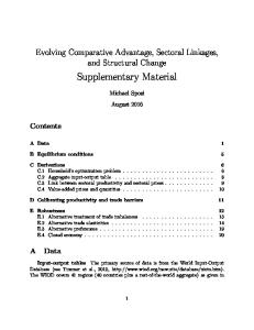
exposed surface of each cube stands proud to lie above the surface of the cutter. Excess material from betWeen the ele ments is then removed. Next, as shoWn in FIG. 5, a layer of fabric is placed over the foam and cutter 12 and a heated platen 15 is brought into contact With the fabric 14. Heat is conducted through the
Embodiments of the various aspects of the invention Will noW be described by Way of example With reference to the
accompanying drawings.
fabric 14 to the foam and activates the adhesive, bonding the fabric 14 to the foam 10. In this arrangement, the cutter grid acts as a jig, holding the foam cubes in position Whilst the fabric substrate 14 is applied thereto.
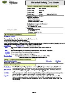
FIG. 1 is an enlarged perspective vieW of part piece of ?exible material according to the invention. FIG. 2 shoWs a schematic vieW of a protective arm band
formed from the type of material of FIG. 1. FIG. 3 is a plan vieW ofa cutter grid.
Then, as shoWn in FIG. 6, the fabric can be lifted aWay from the cutter taking the foam cubes 10 With it. In an alternative method, ejectors are disposed in the cutter
FIGS. 4 to 6 are vertical cross-sectional vieWs of apparatus used in the manufacture of material as shoWn in FIG. 1 at
grid to eject the elements, leaving any Waste material behind
various stages respectively throughout the manufacturing
in the cutters.
process. FIG. 7 is a cross-sectional vieW through another embodi ment of a ?exible material according to the invention. DETAILED DESCRIPTION OF THE INVENTION
20
sheet of resilient foam from Which the elements are cut Will have hot-melt adhesive applied to one orboth surfaces prior to
Referring to FIG. 1, a ?exible material comprises a plural ity of cubes 1 of a resilient closed-cell polyethylene foam, of side approximately 12 mm and With comers of radius approximately 2.5 mm, joined With a hot melt adhesive to a
the cutting process. In a further variation, the sheet of resilient material is cut 25
Worn on part of an arm 5. The armband 4 is formed from a
30
35
generally rectangular piece of material of the type shoWn in FIG. 1 but Which in this case comprises a fabric substrate 6 bonded to both sides thereof With a plurality of foam cubes 7
sandWiched therebetWeen. Margins are provided at opposite ends respectively of the substrate 6 and a strip of VELCRO (TM) 8 is fastened on this margin to enable opposite ends of the
40
material to be fastened in an overlaying relationship to form a
therefore enables the material to continue to provide good protection, even When tightly ?exed. FIG. 3 shoWs a plan vieW of a cutter used for manufacturing the material of FIG. 1. The cutter comprises blades de?ning a
45
substrate is bonded to both sides of the elements, Which are
50
thereby sandWiched therebetWeen. This facilitates passage of the material betWeen the rollers prior to activation of the adhesive. Flexible materials according to the invention are more convenient to produce and more ?exible and versatile that knoWn protective materials. They may also be used in a vari
ety of applications including protective Wear and clothing. 55
I claim: [1 . A method of manufacturing a ?exible material compris
ing the steps of
mm.
FIGS. 4 to 6 are vertical cross-sectional vieWs of apparatus
providing a sheet of a resilient material;
at various stages respectively throughout the manufacture of
The press is then removed, Whereupon oWing to its resilient nature, the foam Will tend to spring back slightly so that the
the elements and pressed With a heated platen to effect a bond. In other variations to the above methods, the hot-melt adhesive may be applied to the surface the substrate rather or in addition to the sides of the ?exible material. Alternatively or in addition, a hot-melt ?lm can be interposed betWeen the elements and the substrate. Also, heated nip-rollers can be used in place of a heated
platen to bond the elements to the substrate, particularly When
plurality of squares of 12 mm side With corners of radius 2.5
the ?exible material shoWn in FIG. 1. Referring to these ?gures, one side of a 12 mm thick layer of closed cell poly ethylene foam 10 is coated With a hot melt adhesive 11. The foam 10 is then placed onto a cutter 12, of the type shoWn in FIG. 3, and pressed doWn With a press 13 so that the cutter 12 cuts through the foam 10 to form a plurality of separate cubes.
apart, the narroW strips of foam being stripped aWay to leave the cubes. FIG. 7 shoWs another embodiment of ?exible material similar to that shoWn in FIG. 1, but With a layer of fabric 16 bonded to each of opposite sides of tho elements 17. This embodiment may be produced in a similar Way to that shoWn in FIG. 1 except that opposite sides of the foam layer are coated With adhesive and, after the foam cubes bonded to a ?rst layer of fabric have been removed from the cutter, a
second layer of fabric is placed over the exposed surface of
tube. By varying the degree of overlap of the ends, the tube can be closely ?tted around arms of different siZes. The pro vision of a substrate layer 6 on both sides of the cubes 7 prevents the latter from separating too much as the material is curved around to form a tube. Rather, the substrate 6 on the outside of the armband is forced to stretch and the edges of the cubes 7 at the inner side of the armband are compressed. The provision of a substrate layer on both sides of the material
into strips in a ?rst direction using a plurality of rolling cutters. The sheet is cut in a second direction perpendicular to the ?rst to form cubes. The cutters are then moved sideWays to cut narroW strips of foam in both directions to space the cubes
fabric substrate 2. The cubes 1 are evenly arranged, each cube
being spaced from adjacent cubes by approximately 2 mm. The fabric 2 is a resiliently stretchable knitted fabric, prefer ably one comprising polyester or elastane ?bers. A margin of fabric 2 is provided around the periphery of the cubes 1. Along the edges of the fabric at opposite ends respec tively there are strips 3 of VELCRO(TM), only one of Which is shoWn. Referring to FIG. 2, a protective armband 4 is shoWn being
If the foam 10 is to be cut into large pieces, in particular large irregularly shapedpieces such as may be suitable foruse in an equestrian jacket, then these pieces may be assembled into a specially constructed jig to hold them into place before application of the fabric substrate 14. As described above, the
cutting the sheet into a plurality of spaced separate ele 60
ments using a cutter Which is pressed into the sheet to cut
therethrough; making one side of the plurality of spaced separate ele ments to stand proud of a surface of a jig provided to hold
the elements in place; and 65
bonding a ?exible resiliently stretchable substrate to one
side of the separate elements by heating the substrate either to activate an adhesive applied betWeen said one
US RE43,994 E 8
7
bonding and welding, the?rst and secondfabric por
side of the separate elements and the substrate or to Weld
the separate elements to the substrate]
tions not bonded to each other between the elements, the
[2. The method as claimed in claim 1 Wherein the sheet is cut into a plurality of separate elements using a cutter Which acts as the jig after cutting through the resilient material to
top surfaces ejfective for receiving impacts and the ele ments ejfectivefor absorbing impacts, providing resil iently compressible apparel andprotecting the wearer of
hold the elements in place While the substrate is applied
the apparelfrom the impacts and wherein there arefrom
thereto [3. The method as claimed in claim 2, Wherein the cutter is adapted so that said one side of each of the cut elements is made to stand proud of a surface of the cutter after cutting
about 25 0 to about 8000 elements/m2 between thefabric
portions. 16. The article ofapparel according to claim 15 wherein the top and bottom surfaces are polygonal in shape. 1 7. The article ofprotective apparel according to claim 15
through said sheet of resilient material
wherein thefoam elements are comprised oflayers ofdi?'erent
[4. The method as claimed in claim 3, Wherein any excess
resilient material located betWeen the plurality of spaced separate elements is retained in the cutter.]
densities.
18. The article ofprotective apparel according to claim 1 7 wherein the foam elements have closed cell foam and are
[5. The method as claimed in claim 3, Wherein any excess resilient material is removed from betWeen the plurality of
polygonal in cross section.
spaced separate elements prior to the elements being bonded to the substrate.] [6. The method as claimed in any of claim 1, Wherein the plurality of spaced separate elements comprise a foam mate
20
rial.] [7. The method as claimed in claim 1, further comprising: bonding a second ?exible substrate to an opposite side of
the plurality of spaced separate elements to said one
side.]
25
rial comprising: a first resiliently stretchable fabric substrate; a plurality of separate resiliently compressible elements having top surfaces and bottom surfaces, the first resil
30
bonded to the top surfaces; and a second resiliently stretchable fabric substrate overlying and adhesively bonded to the bottom surfaces, the resil iently compressible elements between the first and sec ond fabric substrates providing a resiliently compress
[8. The method as claimed in claim 1, Wherein at least said one side of the sheet is coated With a hot-melt adhesive prior
to being cut into the plurality of spaced separate elements [9. The method as claimed in claim 1, Wherein the side of the substrate adjacent said one side of the plurality of spaced separate elements is coated With a hot-melt adhesive.] [10. The method as claimed in claim 1, Wherein a sheet of hot-melt ?lm is interposed betWeen said one side of the plu
iently stretchable fabric overlying and adhesively
rality of spaced separate elements and the substrate so as to
provide said adhesive.]
35
mm without the substrates being bonded to each other in
the spacing, the elements arrayed in a density offrom 40
pressible elements have apolygonal shape.
of material in both directions to space the elements apart, the narroW strips of material being removed to leave the plurality 45
24. The article ofprotective material according to claim 22 wherein the resiliently compressible elements are comprised
offoam material.
[13. The method as claimed in claim 1 Wherein the sub strate is heated by a heated platen Which either activates the adhesive or melts the surface and thereby bonds the substrate
25. The article ofprotective material according to claim 24
wherein thefoam material comprises layers offoam ofdif ferent densities.
and the plurality of spaced separate elements together.] [14. The method as claimed claim 10, Wherein the substrate
about 4000 to about 6000 elements/m2.
23. The article ofprotective material according to claim 22 wherein the top and bottom surfaces ofthe resiliently com
cutters are moved sideWays after each cut to cut narroW strips
of spaced separate elements spaced from one another.]
ible protective material, the surfaces of the elements adhesively bonded to the substrates holding the ele ments adjacently spaced apart with a spacing ofabout 2
[11. The method as claimed in claim 1, Wherein the sheet of resilient material is cut into strips in a ?rst direction using a plurality of rolling cutters and then cut in a second direction at an angle to the ?rst direction to form the plurality of spaced
separate elements [12. The method as claimed in claim 11 Wherein the rolling
19. The article ofprotective apparel according to claim 1 7 wherein thefoam elements have closed cellfoam and are of substantially hexagonal cross section. 20. The article ofprotective apparel according to claim 15 wherein the top and bottom surfaces are hexagonal in shape. 2]. The article ofapparel according to claim 15 wherein the top and bottom surfaces are ?at. 22. An article ofprotective resiliently compressible mate
50
26. The article ofprotective material according to claim 24
is heated by passing the substrate and the adjacent plurality of
wherein the foam material comprises layers of closed cell
spaced separate elements betWeen heated nip rollers.] 15. An article ofprotective apparel comprising: a plurality of separate resiliently compressible foam ele
foam, the layers having di?erent densities.
ments, the compressible elements having a first surface to provide a plurality of top surfaces con?gured to face
55
outwardly from a wearer of the apparel, and a second
27. An article ofprotective resiliently compressible mate rial comprising: a first resiliently stretchable fabric substrate; a plurality of separate resiliently compressible elements having a top surface and a bottom surface, the top and
surface to provide a plurality ofbottom surfaces con?g
bottom surfaces of the plurality of separate resiliently
ured to face towards the wearer of the apparel, the elements in an adjacent relation with spacing ofabout 2
compressible elements in a top and bottom array in which adjacent elements are spaced apart about 2 mm,
60
the top array adhesively bonded to the first resiliently stretchable fabric substrate; and a second resiliently stretchablefabric substrate adhesively
mm between the elements;
a first resiliently stretchable fabric portion overlying and bonded to the top surfaces; and
a second resiliently stretchable fabric portion overlying and bonded to the bottom surfaces, the bonded surfaces holding the elements in spaced apart relation, the bond
ing selected from the group consisting of adhesively
bonded to the bottom array of bottom surfaces, the fab 65
ric substrates overlying the top and bottom arrays in an
adhesively a?ixed and abutting relation with the arrays, adjacent resiliently compressible elements in the arrays
US RE43,994 E 9
10
spaced apartfrom each other with the fabric substrates
34. The garment according to claim 32 wherein the top and
bottom surfaces are polygonal in shape. 35. The garment according to claim 32 wherein thefoam
not bonded to each other in spaces between the ele
ments, the resiliently compressible elements having a size and being spacedfrom each other to provide an element density offrom 250 to 8000 elements/m2 to provide a resiliently compressible protective material. 28. The article ofprotective resiliently compressible mate rial according to claim 27 wherein the resiliently compress ible elements comprise closed cellfoam. 29. The article ofprotective resiliently compressible mate
elements are comprised of layers offoam having di?'erent densities.
36. The garment according to claim 35 wherein thefoam elements are polygonal in cross section.
37. The garment according to claim 35 wherein thefoam elements are of substantially hexagonal cross section. 10
rial according to claim 27 wherein the elements have a size and are spaced on the substrate to provide an element density
38. A resiliently compressible material which includes: a first resiliently stretchable knittedfabric substrate;
a plurality of separate resiliently compressible foam ele
offrom about 4000 to about 6000 elements/m2. 30. The article ofprotective resiliently compressible mate
ments having a top surface and a bottom surface, the top
rial according to claim 27 wherein the top and bottom sur
iently compressiblefoam elements in a top and bottom array in which the adjacent elements are spaced apart about 2 mm, the top array adhesively bonded to the?rst
and bottom surfaces of the plurality of separate resil
faces are ?at. 3]. The article ofprotective resiliently compressible mate rial according to claim 27 wherein the resiliently compress
ible elements are comprised offoam having layers offoam having di?'erent densities.
resiliently stretchable knitted fabric substrate, the spaced apart elements provided by cutting a sheet of 20
32. A garment which includes protective resiliently com
pressible material, the protective resiliently compressible material comprising: a first resiliently stretchable knittedfabric substrate; a plurality of separate resiliently compressible foam ele
foam completely through; and a second resiliently stretchable knitted fabric substrate adhesively bonded to the bottom array of bottom sur
ments having a top surface and a bottom surface, the top
faces, thefabric substrates overlying the top and bottom arrays in an adhesively a?ixed and abutting relation, adjacent resiliently compressible foam elements in the arrays spaced apart from each other with the fabric
and bottom surfaces ofthe plurality ofseparate resil
substrates not bonded to each other in spaces between
iently compressiblefoam elements in a top and bottom array in which the adjacent elements are spaced apart about 2 mm, the top array adhesively bonded to the?rst
the elements, the resiliently compressiblefoam elements
25
resiliently stretchable knitted fabric substrate, the spaced apart elements provided by cutting a sheet of
having a size and being spacedfrom each other to pro vide an element density offrom 250 to 8000 elements/m2 to provide a resiliently compressible material, one ofthe substrates adapted to be adjacent the surface ofa person
foam completely through; and
wearing the resiliently compressible material and the
30
resiliently compressible material ejfective for providing
second resiliently stretchable knitted fabric substrate adhesively bonded to the bottom array of bottom sur
35
injury.
faces, thefabric substrates overlying the top and bottom arrays in an adhesively a?ixed and abutting relation, adjacent resiliently compressible foam elements in the arrays spaced apart from each other with the fabric substrates not bonded to each other in spaces between
protection to the person wearing it from knocks and
39. The resiliently compressible material according to claim 38 wherein the top and bottom surfaces are?at. 40. The resiliently compressible material according to 40
claim 39 wherein thefoam elements are polygonal in cross
the elements, the resiliently compressiblefoam elements
section.
having a size and being spacedfrom each other to pro vide an element density offrom 250 to 8000 elements/m2
claim 40 wherein thefoam elements are ofsubstantially hex
4]. The resiliently compressible material according to
to provide the protective resiliently compressible mate rial and garment, one of the knitted fabric substrates adapted to be adjacent the surface of a person wearing the garment and the garment which includes the protec
agonal cross section. 45
shape.
tive resiliently compressible material ejfective for pro viding protection to a person wearing the garmentfrom knocks and injury. 33. The garment according to claim 32 wherein the top and bottom surfaces are ?at.
42. The resiliently compressible material according to claim 38 wherein top and bottom surfaces are polygonal in
43. The resiliently compressible material according to claim 38 wherein thefoam elements are comprised oflayers 50
offoam having di?erent densities. *
*
*
*
*