Fluid Mechanics
Chapter 6 – Momentum Equation
6 MOMENTUM EQUATION 6.1 Momentum and Fluid Flow
In mechanics, the momentum of a particle or object is defined as the product of its mass m and its velocity v: Momentum
= mv
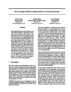
The particles of a fluid stream will posses momentum and whenever the velocity of the stream is changed in magnitude and direction, there will be a corresponding change in the momentum of the fluid particles. In accordance with Newton’s second law, a force is required to produce the change, which will be proportional to the rate at which the change of momentum occurs. Consider a control volume in the form of a straight section of a streamtube ABCD.
v1δ t A A1 v1 ρ1
-
B
v2δ t C'
C A'
A2 v2 ρ2
B'
D
D'
A steady flow and uniform velocity are assumed at all points in a given cross-section. After a small interval of time δt, the fluid originally contained in ABCD will have moved to A’B’C’D’: Distance AA’ = v1δt, Distance CC’ = v2δt,
-
Since the mass of fluid remains unchanged, mass occupying CC’D’D will be equal to the mass occupying AA’B’B
P.6-1
Fluid Mechanics
i.e.
Chapter 6 – Momentum Equation
ρ2 A2 v2δt
= ρ1 A1 v1δt
The momentum of the fluid ABCD will change in moving to A’B’C’D’. Change of momentum of fluid ABCD in time δt
Increase of = momentum due to fluid CC’D’D
Momentum of fluid CC’D’D
Similarly, Momentum of fluid AA’B’B
Momentum of - fluid AA’B’B
= mass * velocity = ρ2 A2 v2δt * v2 = ρ2 A2 v22δt = ρ1 A1 v12δt
Hence change of momentum of fluid between AB and CD in unit time = ρ2 A2 v22δt - ρ1 A1 v12δt Dividing by δt Rate of change of momentum of fluid between AB and CD = ρ2 A2 v22 - ρ1 A1 v12
From continuity of flow, ρ1 Q1 =
ρ2 Q2
By assuming the densities of the fluid at entry and exit sections remain the same, hence Rate of change of momentum between AB and CD = ρ*(Q2v2 – Q1v1) (6.1)
According to Newton’s second law, the increase of momentum per unit time in the direction of motion, and will be caused by a force F, such that F = ρ*(Q2v2 – Q1v1) (6.2) This is the resultant force acting on the fluid element ABCD in the direction of motion.
P.6-2
Fluid Mechanics
The value of F being positive in the direction in which v is assumed to be positive. For any control volume, the total force F which acts upon it in a given direction will be made up of three component forces: F1
= Force exerted in the given direction on the fluid in the control volume by any solid body within the control volume or coinciding with the boundaries of the control volume.
F2
= Force exerted in the given direction on the fluid in the control volume by body forces such as gravity.
F3
= Force exerted in the given direction on the fluid in the control volume by the fluid outside the control volume.
Thus,
Chapter 6 – Momentum Equation
F = F1 + F2 + F3 = ρ*(Q2v2 – Q1v1)
(6.3)
The force R exerted by the fluid on the solid body inside or coinciding with the control volume in the given direction will be equal and opposite to F1 so that R
= -F1
(6.4)
P.6-3
Fluid Mechanics
Chapter 6 – Momentum Equation
6.2 Force exerted by a Jet striking a Flat Plate
A v
θ
When a jet of fluid strikes a stationary flat plate at an angel θ, it does not rebound, but flows out over the plate in all direction. In a direction normal to the surface of the plate, the velocity of the stream will be reduced to zero and the momentum normal to the plate destroyed. In the direction parallel to the plate, the force exerted will depend on the shear stress between the fluid and the surface of the plate. For an ideal fluid, there would be no shear stress and no force parallel to the plate. The fluid would flow out over the plates so that the total momentum per second parallel to the plate remained unchanged. The control volume taken is fixed relative to the plate. The x direction is chosen perpendicular to the surface of the plate. Force exerted by fluid on plate in x direction, R = -F1 = F2 + F3 -ρ*(Qoutvout – Qinvin)x
The gravity force F2 is negligible and if the fluid in the jet is assumed to be at atmospheric pressure throughout, F3 is zero. Thus, R = - ρ*Q*(vout - vin)x (6.5) = ρ*Q *(vin - vout)x Since vin and vout are measured relative to the control volume, which is fixed relative to the plate, so that (vin - vout)x = (Initial velocity - Final velocity) relative to the plate in x direction
P.6-4
Fluid Mechanics
Chapter 6 – Momentum Equation
(a) The plate is stationary Mass entering control volume per unit time
= =
Mass leaving nozzle per unit time ρAv (A = area of jet)
Initial component of velocity relative to plate in x direction = v cosθ Final component of velocity relative to plate in x direction =0 (Initial velocity - Final velocity)x
= v cosθ
Therefore, Force exerted on plate in x direction = ρAv(v cosθ) = ρAv2 cosθ
(6.6)
(b) The plate moves in the same direction as the jet with velocity u. u in unit time
A v
θ
u
The jet will be continually extending by a length u per unit time.
Taking the control volume as fixed relative to the plate, Mass per unit time entering control volume
= Mass per unit time leaving nozzle = ρAv - ρAu = ρA(v - u)
- Mass per unit tiem required to extend the jet
Initial component of velocity relative to plate in x direction = (v - u) cosθ, Final component of velocity relative to plate in x direction = 0, (Initial velocity - Final velocity)x = (v - u) cosθ Force exerted on plate in x direction = ρA(v - u)2 cosθ (6.7)
P.6-5
Fluid Mechanics
Chapter 6 – Momentum Equation
Worked examples: 1.
A jet of water of 22.5 cm diameter impinges normally on a flat plate moving at 0.6 m/s in the same direction as the jet. If the discharge is 0.14 m3/s, find the force and the work done per second on the plate.
Answer = 1000 kg/m3 = π*(0.225)2/4 m2 = 0.0398 m2 velocity of jet, v = Q/A = 0.014/0.0398 m/s = 3.52 m/s plate moving, u = 0.6 m/s
Density of water, ρ Area of jet, A
F2 = 0 F3 = 0 (free jet) F1 = ρA(v - u)2 cosθ = 1000*0.0398*(3.52-0.6)2 N = 339 N (force on jet, ←) Force on the plate, R = -F1 = -339 N (→) Work done on plate / sec
=F*u = 339 * 0.6 Nm/s or J/s or W = 204 W
P.6-6
Fluid Mechanics
2
Chapter 6 – Momentum Equation
In an undershot waterwheel the cross-sectional area a of the stream striking the series of radial flat vanes of the wheel is 0.1 m2 and the velocity v of the stream is 6 m/s. The velocity u of the vanes is 3 m/s. Calculate the force F exerted on the series of vanes by the stream.
Answer
A, v u
Since there are a series of vanes on the wheel, the average length of the jet from the nozzle to the point of impact remains constant and all the water from the nozzle strikes one or other of the vanes. Assuming that the diameter of wheel is large so that impact is approximately normal, Mass of water striking vanes/sec Initial velocity of water Final velocity of water change of velocity on impact F2 Force of water on vanes, R Density of water, ρ Area of jet, A R
= ρAv =v = 6 m/s = velocity of vanes =u = 3 m/s = v-u = F3 =0 = ρAv(v-u) = 1000 kg/m3 = 0.1 m2 = 1000*0.1*6*(6-3) N = 1800 N = 1.8 kN
P.6-7
Fluid Mechanics
Chapter 6 – Momentum Equation
6.3 Force of a Jet on a Curved Vane
Hydraulic machinery makes use of the ‘force’ of a liquid. The liquid impinges on a series of blades or vanes connected to the periphery of a wheel, thus driving the wheel. The vanes are usually curved for greater effect as illustrated later. In this chapter, we consider only the force on a stationary vane. When a flat plate is used, the momentum normal to the plate is destroyed. It is more effective to change the direction of the momentum. It can be arranged for the jet to impinge tangentially on a curved vane, so that no momentum is destroyed and the jet is merely deflected. In the following case, the forces parallel to and perpendicular to the dotted line will be calculated. The blade velocity is stationary. v1 inlet
β
α
outlet
v2
Force on jet = ρ*Q* change of velocity of jet = ρ*Q *(final velocity of jet - initial velocity of jet) Force on vane= - Force on jet = ρ*Q *(Initial velocity of jet - final velocity of jet) Rx = ρ*Q *(v1cosα - v2cosβ)
(6.8)
Ry = ρ*Q *( v1sinα - v2sinβ)
(6.9)
P.6-8
Fluid Mechanics
Chapter 6 – Momentum Equation
Worked example: Find the forces on the blade parallel to and perpendicular to the water jet at the inlet. The jet is 50 mm diameter. 30 m/s
30 o
30 m/s
Answer = 1000 kg/m3 = π*(0.05)2/4 m2 = 1.96*10-3 m2 velocity of jet, v = 30 m/s
Density of water, ρ Area of jet, A
� m
= ρAv = 1000*1.96*10-3*30 kg/s = 58.9 kg/s
Force on jet parallel to jet at inlet � *(30 cos30° - 30) =m = 58.9*30*(1 - cos30°) N = 236.8 N (→) Force on jet perpendicular to jet at inlet � *(30 sin30° - 0) =m = 58.9*30*0.5 N (↓) = 883.5 N (↓)
(←) (→)
(↓)
Forces on the blade are 236.8 N (←) and 883.5 N (↑).
P.6-9
Fluid Mechanics
Chapter 6 – Momentum Equation
6.4 Force Exerted on Pipe Bends and Closed Conduits 2 1 p1 A1 v1
p2 A2 v2
φ
y x
θ
on plan
The above diagram shows a bend in a pipeline containing fluid. For a two dimensional problem, both momentum and force can be resolved into components in the x and y directions and the one dimensional momentum applies. When the fluid is at rest, it will exert a static force on the bend because the lines of action of the forces due to pressure p1 and p2 do not coincide. If the bend tapers, the magnitude of the static forces will also be affected. When the fluids is in motion, its momentum will change as it passes round the bend due to the change in its direction and, if the pipe tapers, any consequent change in magnitude of its velocity; there must, therefore, be additional force acting between the fluid and the pipe. The equal and opposite force exerted by the liquid on the pipe is of particular interest, because this force needs to be taken into account when designing for the support of the pipe. The control volume is bounded by the inside wall of the bend and the inlet and outlet section 1 and 2. � = ρQ Mass per unit time entering control volume, m
P.6-10
Fluid Mechanics
Chapter 6 – Momentum Equation
The force acting on the fluid will be F1 exerted by the walls of the pipe, F2 due to gravity (which will be zero), and F3 due to the pressure p1 and p2 of the fluid outside the control volume acting on areas A1 and A2 at sections 1 and 2. The force exerted by the fluid on the bend will be R = - F1. Using the momentum equation, putting F2 = 0 and resolving in the x direction: (F1 + F3)x and, since
= ρ*Q (vout - vin)x
Rx = -F1x
(6.10) (6.11)
Rx = F3x - ρ*Q (vout - vin)x Now
F3x = p1A1cosθ - p2A2cosφ vout = Component of v2 in x direction = v2cosφ, vin = Component of v1 in x direction = v1cosθ
Therefore Rx = p1A1cosθ - p2A2cosφ - ρQ(v2cosφ - v1cosθ) (6.12) Similarly in the y direction, (F1 + F3)y and, since
� (vout - vin)y =m
Ry = -F1y
Ry = p1A1sinθ - p2A2 sinφ - ρQ(v2 sinφ - v1 sinθ) (6.13) Resultant F
=
R x2 + R y2
(6.14)
P.6-11
Fluid Mechanics
Chapter 6 – Momentum Equation
Worked examples:
1.
A high pressure hose 200 mm diameter ends in a nozzle with an exit diameter of 50 mm. The exit velocity is 40 m/s. Calculate the longitudinal force on the nozzle when it is held horizontally.
Answer 1 2 40 m/s
d1 = 200 mm
d2 = 50 mm
By Continuity equation, d v1 = ( 2 ) 2 *v2 d1 50 2 ) *40 m/s =( 200 = 2.5 m/s
p2 z1
= 0 (Patm) = z2 = 0
Apply Bernoulli’s equation between 1 and 2 p1 v12 p2 v22 + + z1 = + + z2 γ γ 2g 2g p1 2.52 40 2 + +0= 0+ +0 9.81 2 * 9.81 2 * 9.81 p1 = 796.88 kPa
F2 = 0 ΣF = F1 + p1*A1 = F1 + 796.88*π*(0.2)2/4 = F1 + 25kN
P.6-12
Fluid Mechanics
Chapter 6 – Momentum Equation
Rate of change of momentum = ρQ*(vout – vin) = 1000*π*(0.2)2/4*2.5*(40 – 2.5) = 2.945 kN F1 + 25 = 2.945 F1 = -22.1 kN Force on the nozzle
N
(←)
= 22.1 kN
(→)
P.6-13
Fluid Mechanics
Chapter 6 – Momentum Equation
2. Water enters a 60° bend in a pipe with a velocity of 3 m/s and a pressure of 100 kPa. At the beginning and end of the bend, the pipe diameters are 400 mm and 250 mm respectively. Calculate the force on the bend.
60o 60o
1
y x
2
Answer
Assume that there is no loss of pressure caused by the bend v1 = 3 m/s p1 = 100 kPa z1 = z2 = 0 By Continuity equation, d v2 = ( 1 ) 2 *v1 d2 400 2 =( ) *3 250 = 7.68 m/s
m/s
Apply Bernoulli’s equation between 1 and 2 p1 v12 p2 v22 + + z1 = + + z2 γ 2g γ 2g 100 32 p2 7.682 + +0= + +0 9.81 2 * 9.81 9.81 2 * 9.81
p2
= 75 kPa
P.6-14
Fluid Mechanics
Chapter 6 – Momentum Equation
F31 = p1*A1 = 100*π*(0.4)2/4 = 12.57 kN F32 = p2*A2 = 75*π*(0.25)2/4 = 3.68 kN F31=12.57 kN y
v1=3 m/s y
F1y
x
x F1x
v2=7.68 m/s velocity diagram
F32=3.68 kN
force diagram
For x-direction,
ΣF = F1x + 12.57*cos 60° - 3.68 = F1x + 2.605 kN Q
= π*(0.4)2/4*3 = 0.377 m3/s
m3/s
By momentum equation, ΣF = ρQ(vout – vin) F1x + 2.605 = 1000*0.377*(7.68 – 3*cos 60°)/1000 F1x = -0.275 kN (←) Similarly for y direction,
ΣF = F1y - 12.57*sin 60° = F1y – 10.89 kN By momentum equation, F1y – 10.89 = 1000*0.377*[0 – (-3*sin 60°)]/1000 F1y = 11.87 kN (↑) Total force on the bend is 0.275 kN (→) and 11.87 kN (↓).
P.6-15
Fluid Mechanics
Chapter 6 – Momentum Equation
Class exercise 6.1:
A jet of water flows smoothly on to a stationary curved vane which turns it through 60°. The initial jet is 50 mm in diameter, and the velocity is 36 m/s. As a result of friction, the velocity of water leaving the surface is 30 m/s. Neglecting gravity effect, calculate the hydrodynamic force on the vane. (Rx = 1.484 kN (→) and Ry = 1.836 kN (↓)) 30 m/s 60
o
36 m/s
P.6-16
Fluid Mechanics
Chapter 6 – Momentum Equation
Class exercise 6.2:
Determine the magnitude and direction of the x and y components of reaction force exerted on the flowing water by the horizontal elbow and nozzle combination shown in the figure below. The water at section 2 exists to the atmosphere. (R = 2.879 kN) 2 160mm y x 2m/s
300mm
1
P.6-17
Fluid Mechanics
Chapter 6 – Momentum Equation
Class exercise 6.3:
Water is sprayed radially outward over 180° as in figure below. The jet sheet is in the horizontal plane. If the jet velocity at the nozzle exit is 6 m/s, determine the direction and magnitude of the resultant horizontal anchoring force required to hold the nozzle in place. (F = 114 N)
200mm
10mm
v=6m/s
P.6-18
Fluid Mechanics
Chapter 6 – Momentum Equation
Tutorial – Momentum Equation
1.
A square plate of uniform thickness and length of side 30 cm hangs vertically from hinges at its top edge. When a horizontal jet strikes the plate at its centre, the plate is deflected and comes to rest at an angle of 30° to the vertical. The jet is 25 mm in diameter and has velocity of 6 m/s. Calculate the mass of the plate and give the distance along the plate from the hinge, of the point at which the jet strikes the plate in its deflected position. x o 15cm
30o
P
A v
2.
W
A
Sections 1 and 2 are at the beginning and end of the bend of the 200 mm diameter pipe in which the quantity of flow is 0.28 m3/s. The angle of deflection of the water is 40°. Calculate the force that the liquid exerts on the bend if the pressure in the pipe is 50 kPa. Assume no loss of pressure round the bend. END
P.6-19