Implementing Two Simplified Coalescent Algorithms Master of Science Thesis in the Master Degree Program Complex Adaptive Systems.
BEHRANG MAHJANI Department of Applied Physics Division of Complex Adaptive systems CHALMERS UNIVERSITY OF TECHNOLOGY Göteborg, Sweden, 2008
Implementing two simplified coalescent algorithms by
Behrang Mahjani
Examiner: Bernhard Mehlig
Thesis Submitted to Chalmers University of Technology Department of Applied Physics
In partial fulfillment of the requirements for awarding of a Master of Science Degree by the University of Chalmers
March, 2008
Implementing two simplified coalescent algorithms
Abstract One of the main goals of population genetics is to expound the causes of empirically observed genetic variation. Coalescent algorithm is a stochastic process that has a powerful role in population genetics. The main use of coalescent algorithm is when one desires to find the common ancestor of n genes in a population of N genes where N is significantly larger than n (N À n). Simplified coalescent algorithms are approximations to Hudson’s coalescent algorithm which run faster than Hudson’s coalescent algorithm. The aim of the present thesis is to analyze the performance and the accuracy of two simplified coalescent algorithms, one suggested by McVean and Cardin (2005) and the other by Paul Marjoram (2006). Comparison of the statistical results shows that although McVean and Marjoram’s coalescent algorithms run faster than Hudson’s coalescent algorithm, they do not generate the same statistical results as Hudson’s coalescent. The statistical results of simplified coalescent algorithms are an approximation to the results of Hudson’s algorithm. In addition, comparison of results shows that Marjoram’s simplified algorithm generates more accurate results (closer to the results to standard coalescent) than McVean’s simplified algorithm.
1
Implementing two simplified coalescent algorithms
ACKNOWLEDGMENTS
I would like to express my gratitude to all those who gave me the possibility to complete this thesis. My thanks are due to Dr. Anders Eriksson for his useful comments and suggestions during writing of my thesis. He proposed a number of excellent hints in a tireless process. Dr. Eriksson motivated me to make new modelling and simulations in this research work. I am deeply indebted to Prof. Bernhard Mehlig whose help, stimulating suggestions and encouragement helped me all the time in this research. I am also thankful to Prof. Serik Sagitov for his guidance in this thesis. I would like to give my special thanks to my parents who gave me support in these years and they have been an inspiration throughout all my life. Finally, I would like to thank my friends Mahmood Rahmani for his useful help with computer programming, and Christina Gustafsson for reading my thesis in detail.
2
Contents 1 Introduction
6
1.1
Some basic definitions in Genetics . . . . . . . . . . . . . . . . . . . . . . . . . .
6
1.2
Mendel’s law . . . . . . . . . . . . . . . . . . . . . . . . . . . . . . . . . . . . . .
7
1.3
Population genetics . . . . . . . . . . . . . . . . . . . . . . . . . . . . . . . . . . .
7
1.4
The Wright-Fisher model . . . . . . . . . . . . . . . . . . . . . . . . . . . . . . .
8
2 Gene genealogies
12
2.1
Introduction . . . . . . . . . . . . . . . . . . . . . . . . . . . . . . . . . . . . . . . 12
2.2
Population models . . . . . . . . . . . . . . . . . . . . . . . . . . . . . . . . . . . 12
2.3
2.2.1
The Wright-Fisher model . . . . . . . . . . . . . . . . . . . . . . . . . . . 13
2.2.2
The Moran model . . . . . . . . . . . . . . . . . . . . . . . . . . . . . . . 14
Mutation Models . . . . . . . . . . . . . . . . . . . . . . . . . . . . . . . . . . . . 15 2.3.1
The infinite-alleles model . . . . . . . . . . . . . . . . . . . . . . . . . . . 15
2.3.2
The infinite-sites model . . . . . . . . . . . . . . . . . . . . . . . . . . . . 16
2.3.3
The finite-sites model . . . . . . . . . . . . . . . . . . . . . . . . . . . . . 17
2.3.4
Genetic recombination . . . . . . . . . . . . . . . . . . . . . . . . . . . . . 17
3 Standard coalescent
19
3.1
Introduction . . . . . . . . . . . . . . . . . . . . . . . . . . . . . . . . . . . . . . . 19
3.2
The coalescent algorithm
. . . . . . . . . . . . . . . . . . . . . . . . . . . . . . . 20
3.2.1
The effective population size . . . . . . . . . . . . . . . . . . . . . . . . . 23
3.2.2
Neutral mutation . . . . . . . . . . . . . . . . . . . . . . . . . . . . . . . . 23
3.2.3
Adding mutations to the basic coalescent algorithm . . . . . . . . . . . . 24
3
CONTENTS
3.3
CONTENTS
The Coalescent algorithm with recombination . . . . . . . . . . . . . . . . . . . . 26 3.3.1
Hudson’s model . . . . . . . . . . . . . . . . . . . . . . . . . . . . . . . . . 27
3.3.2
Wiuf and Hein’s model, sampling along sequences . . . . . . . . . . . . . 31
3.3.3
Adding mutations to the coalescent algorithm with recombination . . . . 32
4 The simplified coalescent algorithms
35
4.1
Introduction . . . . . . . . . . . . . . . . . . . . . . . . . . . . . . . . . . . . . . . 35
4.2
McVean’s simplified coalescent algorithm . . . . . . . . . . . . . . . . . . . . . . . 35 4.2.1
4.3
Discussion . . . . . . . . . . . . . . . . . . . . . . . . . . . . . . . . . . . . 36
Marjoram’s simplified coalescent algorithm 4.3.1
. . . . . . . . . . . . . . . . . . . . . 37
Discussion . . . . . . . . . . . . . . . . . . . . . . . . . . . . . . . . . . . . 39
5 Results and Discussion
40
5.1
Analyzing Hudson’s coalescent algorithm . . . . . . . . . . . . . . . . . . . . . . . 40
5.2
Analyzing McVean’s simplified coalescent algorithm . . . . . . . . . . . . . . . . 43
5.3
Analyzing Marjoram’s simplified coalescent algorithm . . . . . . . . . . . . . . . 46 5.3.1
Verifying the computer programs . . . . . . . . . . . . . . . . . . . . . . . 48
5.4
Relation of mutations and correlation of genes . . . . . . . . . . . . . . . . . . . . 49
5.5
Mosaic structures . . . . . . . . . . . . . . . . . . . . . . . . . . . . . . . . . . . . 51
5.6
Conclusion
. . . . . . . . . . . . . . . . . . . . . . . . . . . . . . . . . . . . . . . 56
Appendices
56
A Computer programs description (Hudson’s algorithm)
57
A.1 Program description, Hudson’s model for two genes . . . . . . . . . . . . . . . . . 57 A.2 Data structures and important variables . . . . . . . . . . . . . . . . . . . . . . . 57 A.3 Description of the functions . . . . . . . . . . . . . . . . . . . . . . . . . . . . . . 60 A.4 Program description, Hudson’s model for three genes . . . . . . . . . . . . . . . . 61 B Computer programs description (McVean and Marjoram’s algorithm)
62
B.0.1 Mcvean’s algorithm . . . . . . . . . . . . . . . . . . . . . . . . . . . . . . 62
4
CONTENTS
B.0.2 Marjoram algorithm . . . . . . . . . . . . . . . . . . . . . . . . . . . . . . 63 Bibliography
64
5
Chapter 1
Introduction Mendel in 1866 published his work about artificial fertilization on pea plants [16]. His experiments were conducted to obtain new variations in the colours of pea plants. Mendel’s work was the beginning of explaining hereditary characteristics, from parents to offspring, which was later called Mendelian inheritance or Mendel’s laws. It is necessary to address some basic definitions in genetics before describing Mendel’s law.
1.1 Some basic definitions in Genetics Information about hereditary characteristics is coded in DNA. DNA is a polymer that consists of molecules called nucleotides. There are four different types of nucleotides which can be distinguished by their bases. These bases are cytosine (C), adenine (A), guanine (G) and thymine (T) [17]. DNA has a special structure in cells which is called chromosome [18]. Thousands of genes are located in each chromosome. A gene is a particular segment of DNA that specifies the structure of a protein; A gene describes the characteristics of offspring which are inherited from parents. Each gene can exist in different forms. These alternative forms of a gene are called Alleles [14].
6
CHAPTER 1. INTRODUCTION
1.2 Mendel’s law As it is already mentioned, Mendel was the first person who explored the laws of heredity [18]. Mendel’s law has two parts, the first law is called law of segregation and the second law is called law of independent assortment. The first Mendel’s law (law of segregation) consists of four parts. The first mendel’s law: 1. Variations in inherited characteristics are caused by different alleles. 2. Each offspring gets one allele from the father and one allele from the mother. 3. For each offspring, if two alleles (inherited from the parents) are different, one of them will be dominant (results in a specific physical characteristic) and one will be recessive (does not result in a specific physical characteristic). 4. Two alleles (inherited from the parents) segregate during sex cells (gametes) production. The second law of Mendel (law of inheritance) indicates that different characteristics are inherited independently.
The science of genetics is divided into four major fields [18]: Transmission genetics, molecular genetics, population genetics and quantitative genetics. The present thesis is devoted to a specific part of population genetics.
1.3 Population genetics Population genetics studies heredity traits which are caused by one or a few number of genes in a population of individuals (genes) [18]. One of the aims of population genetics is to find the causes of genetic variation. The evolutionary changes of genes in one or more species are investigated by population genetics through time to explore the causes of genetic variation. Two important causes of genetic variation are mutations and genetic recombination. In genetic recombination for two strands of DNA (in the simplest model), each strand of DNA 7
CHAPTER 1. INTRODUCTION
breaks and rejoins to the other strand of DNA. In other words, genetic recombination is a kind of ”exchange of genetic materials” between two DNA [18]. A mutation is a change in a gene which can be caused by an error in copying genetic materials [18]. In order to analyze the evolutionary changes, one traces the genes’ ancestries (the genealogy of the genes) from the time of the most recent common ancestor (MRCA) of genes (TM RCA in Figure 1.4) to the present (TP resent in Figure 1.4). Therefore the MRCA has the key role in a genealogy of the genes. A model is needed to explain the genealogy of the genes.
1.4 The Wright-Fisher model The Wright-Fisher model can be employed to describe the genealogical relationship of the genes. In this model, each new generation is generated by random copying of the genes from the previous generation to the new generation. The Wright-Fisher model is based on some assumptions which make the model rather unrealistic. Some of these assumptions are [1]: 1. Generations are discrete and non-overlapping. In other words, all (parents) genes die at the same time in each generation and the next generation only consists of offspring. 2. Population is haploid. 3. The population size is constant. 4. There are no geographical structures in the population. 5. There is no genetic recombination in the population. Note: A diploid individual have two copies of each chromosome, one from the father and one from the mother. A haploid individual has one copy of each chromosome from her parents. A population of 2N genes can be considered as N diploid individuals or 2N haploid individuals [1].
8
CHAPTER 1. INTRODUCTION
A genealogy can be traced backward-in-time or forward-in-time. Tracing a genealogy (in the Wright-Fisher model) is explained in detail in Box 1.4.
Box 1.4: Tracing a genealogy in the Wright-Fisher model Consider a population of 2N genes. The genealogy of two specific genes (gene 1 and gene 2) is of interest. The genealogy of the whole population (2N genes) from the time of the MRCA (TMRCA) of gene 1 and gene 2 to the present should be traced to get the desired genes’ ancestries. In this approach, the genes’ ancestry is traced forward-in-time. An example of this procedure is illustrated in Figure 1.4. Since the genealogy of the other genes does not affect the genealogy of the desired genes, it is also possible to trace the genealogy backward-in-time.
T
MRCA
Figure 1.4: The genealogy of the
Present
Forward in time
Backward in time T
1
genes represented by the WrightFisher model (The MRCA of gene 1 and gene 2 is of interest). The arrows show the direction of tracing the genealogy.
2
Assume one attemps to find out the genealogical relation of n genes among 2N genes (n << N ); With the coalescent algorithm one can trace the genes’ ancestry of those n genes backwardin-time instead of tracing the genealogy of the whole population forward- in-time. This is the main benefit of the coalescent algorithm. The coalescent algorithm started with the work of Watterson (1975). He presented a stochas-
9
CHAPTER 1. INTRODUCTION
tic process that generates a genealogical relationship between n samples of a population size 2N [8]. Kingman (1982) followed Watterson’s work and explained the coalescent algorithm for the first time [8]. Hudson (1983) added genetic recombination to the coalescent algorithm [8]. In each step of Hudson’s algorithm, either a pair of genes coalesce or one gene recombines to two new genes. This procedure continues until all parts of the genes find their MRCA. An alternative coalescent algorithm to Hudson’s coalescent algorithm has been introduced by Wiuf and Hein (1999). Hudson’s coalescent algorithm traces the genealogy of genes backwardin-time. In his algorithm, recombination events and coalescence events occur during tracing the genealogy. In Wiuf and Hein’s algorithm, the genealogy of the genes changes while moving along the genes (updating genes from left to right). A gene can be considered, loosely, as a sequence of letters A,T,G,C. In other words, Wiuf and Hein’s algorithm does not trace the genealogy of the sequences backward-in-time. Instead, Wiuf and Hein’s algorithm runs along sequences; it updates the genealogy whenever it encounters a recombination point along sequences. This process continues until the end of the sequences is reached [8]. It is important to know that this process is not a Markov process [8]. A Markov process is a stochastic process where the probability distribution of the next step depends only on its present state. Markov processes have many properties which can help to explore the process. McVean and Cardin (2005) modified Wiuf and Hein’s algorithm to write an algorithm that runs faster. Their simplified coalescent algorithm is an approximation to Wiuf and Hein’s algorithm. The size of the genealogy of genes in McVean and Cardin’s algorithm is independent of the recombination rate which can make the algorithm run faster. Another benefit of McVean and Cardin’s algorithm is that this process is a Markov process during the sequential generations along the sequences. The main difference between McVean and Cardin’s algorithm and Wiuf and Hein’s algorithm is that in McVean and Cardin’s algorithm coalescent between sequences which do not intersect by each other is not allowed. This changes the results of statistical analysis on McVean and Cardin’s simplified coalescent algorithm, in comparison with Hudson’s algorithm and Wiuf and Hein’s algorithm.
10
CHAPTER 1. INTRODUCTION
Marjoram and Wall (2006) suggested a modification to McVean and Cardin’s simplified coalescent algorithm to get a more accurate statistical results (results which are closer to Hudson’s algorithm and Wiuf and Hein’s algorithm) in comparison to McVean and Cardin’s simplified coalescent algorithm. The primary aim of this thesis is to analyze two simplified algorithms for the coalescent algorithm with recombination. At first, this thesis explore the work of McVean and Cardin (2005) and then the work of Marjoram and Wall (2006). Computer simulations are used to compare these two simplified coalescent algorithms to the standard coalescent algorithm (Hudson’s coalescent algorithm). In addition, probability distributions of the time to the most recent common accentor of genes for these algorithms are explored.
11
Chapter 2
Gene genealogies 2.1 Introduction One of the primary interests in population genetics is to explore the evolutionary processes of genes for one single species with the aim of finding the causes of genetic variations. Experimental and simulated data provide a basis to do statistical analysis on genetic variation in order to find out the main factors that can cause genetic variation and to reveal the influences of them on the population. Some of the main factors that cause genetic variation are mutation, selection, recombination, and geographical structure of the population.
2.2 Population models Population models are employed to describe changes in genes over time. In some population models stochastic processes are used to generate sample sequences of genes and relate them together. The Wright-Fisher model and the Moran model, as two population models, are considered in the present thesis. Population models can be based on diploid or haploid populations. In the diploid population each gene has two copies. If those copies are not similar then those are different alleles of that gene. In the haploid population there is just one copy of each gene [1]. Generations in a population can be overlapping or non-overlapping. In the case of overlapping generations both parents and offsprings can live in the same generation. In the case of non-overlapping generations all parents in each generation die and therefore they do not
12
CHAPTER 2. GENE GENEALOGIES
Figure 2.1: The Wright-Fisher model Each circle stands for one gene. A sample population of 12 genes is presented. Offsprings of each gene are connected to their parent by a line.
continue living with their offsprings in the next generation [1].
2.2.1
The Wright-Fisher model
A population model was introduced by Fisher (1930) and Wright (1931). This model is a stochastic process that describes how genes change from one generation to the next generation. Consider a fixed diploid population of N genes or a fixed haploid population of 2N genes. Assume that generations are discrete and non-overlapping. Each gene in the generation t + 1 is obtained by copying a random gene from the generation t. This rule defines the Wright-Fisher model. This definition clearly shows that each gene in the generation t has only one parent in the generation t + 1 but can have many offsprings in the generation t + 1. An example of this model is illustrated in Figure 2.1. It is also clear that the population size do not change in the Wright-Fisher model. To get a mathematical description for the Wright-Fisher model one can calculate the number of descendants of each gene in one generation. Each gene in one generation is chosen independently, therefore gene i can be chosen each time in one generation by probability 1/2N which is the case of binomial distribution with parameters 2N and 1/2N . Therefore the probability that gene i has k descendants in the next generation is [1]: µ P (Xi = k) =
¶ 1 2N −k 2N 1 k ) (1 − ) ( 2N 2N k
Where Xi is a random variable as the number of descendants of gene i.
13
(2.2.1)
CHAPTER 2. GENE GENEALOGIES
Figure 2.2: The Moran model Each circle stands for one gene. A sample population of 7 genes is presented. Offspring of each gene are connected to their parent by a line. A few generations are illustrated in this figure.
Easily one can conclude [1]: E(Xi ) = 1
(2.2.2)
This shows that the population size is constant. Finally, it can be concluded that [1]:
V ar(Xi ) = 1 −
2.2.2
1 2N
(2.2.3)
The Moran model
As it is already mentioned (see 2.2.1), the Wright-Fisher model is based on non-overlapping generations. Moran introduced another population model that is based on overlapping generations. In this model, in each generation one gene randomly dies and one gene randomly gives birth to a new gene (all other genes will live in the next generation), see Figure 2.2.
The probability that two genes have the same ancestor a generation ago is
1
(2N 2 )
[1]. Therefore
the time to the most recent common accentor (TMRCA) of two genes is geometrical distributed with the parameter
1
(2N 2 )
.
14
CHAPTER 2. GENE GENEALOGIES
2.3 Mutation Models A mutation is a change in a gene that can be caused by an error in copying genetic material from parents to offspring. The change in the gene can be a base pair substitution, insertion, deletion, or rearrangement [18]. To model empirical data one should have a model to describe how mutations cause changes in DNA. Three models of mutation are explained in the present thesis; the infinite-alleles model introduced by Kimura and Crow (1964), the finite-sites model introduced by Jukes and Cantor (1969) and finally the infinite sites model introduced by Kimura (1969).
2.3.1
The infinite-alleles model
In this model a mutation always results in a new allele not observed before. Actually, the only information provided by this model is whether two alleles are similar or not. Therefore it is not possible to know if there were more than one mutation between two alleles in this model. Hence this model is unable to provide any information about the number and the order of the alleles. Figure 2.3 is an example of the infinite alleles model. There are five genes in the example. At first there is only one gene, gene 1. After that, gene 1 splits into two new genes, gene 1 and gene 2. Gene 1 and gene 2 in this step have the same allelic type which is shown as (1, 2) (The same alleles of genes are always shown in the same parentheses). A mutation occurs in the next step thus gene 1 and gene 2 become two different alleles. These two different alleles are shown as (1), (2). Again another mutation happens but this mutation does not make a new allele. After that gene 2 splits into two new genes (2, 3). Here gene 2 and gene 3 have the same allelic type. In the next step gene 3 splits into two new genes. Therefore the new configuration is (1), (2, 3, 4) which means that there are four genes where gene 1 is a different allele from gene 2, gene 3 and gene 4. A mutation occurs in gene 4 in the next step and the configuration changes into (1), (1, 2)(4). Consequently, gene 4 spilt into two new genes (4, 5). Finally a mutation happens for gene 2 in the next step and it becomes a new allele. At the end, the configuration is (1), (2), (3), (4, 5). This configuration demonstrates four different alleles among five genes
15
CHAPTER 2. GENE GENEALOGIES
..
(1)
(1,2) (1),(2) (1),(2)
.
. 1
2
(1),(2,3) (1),(2,3,4) (1),(2,3),(4) (1),(2,3),(4,5) (1),(2),(3),(4,5)
4
3
5
Figure 2.3: Infinite alleles model Mutations are shown as dots. The same alleles of the genes are shown in the same parentheses.
where gene 4 and gene 5 are the same allele. As it is shown in Figure 2.3, there are two mutations on the first branch (the line that is connected to gene 1) but only one of these mutations is distinguishable in the infinite- alleles model.
2.3.2
The infinite-sites model
In this model of mutation, genes are considered as a very long sequence of zeros and ones (more than 105 ). Therefore, each site (each place in the sequence of zeros and ones) can have two states, either mutated (one) or not mutated (zero). The mutation rate per each site is very low (less than 10−6 ) in this model [1]. An example of this model of mutation is illustrated in Figure 2.4. In this figure each gene is shown as a line and mutations are shown as dots. As it is shown in the Figure 2.4, there are two mutations on the first branch (for gene 1). With the infinite-alleles model, as it is already described (see 2.3.1), these two mutations are not distinguishable (see Figure 2.3) but they are distinguishable with the infinite-sites model.
16
CHAPTER 2. GENE GENEALOGIES
. .. ..
. .
.. ..
1
2
. .
. .
4
3
.
5
Figure 2.4: The infinite sites model Mutations are shown as dots.
To compare genes in the infinite-sites model, only the sites which have mutated (segregating sites, SNPs) might be considered and the other sites should be ignored. This simplification is helpful to store less information about genes with easier and faster calculation.
2.3.3
The finite-sites model
In the finite-sites model, an attempt is made to build a more realistic model of mutation. Some mutation cases which are not considered in the infinite-sites model and the infinite-alleles model are considered in the finite-sties model (i.e. mutation happens in the same site). In reference [14] more details of this model are explained.
2.3.4
Genetic recombination
In genetic recombination two strands of DNA break and then they rejoin together. Recombination can occur between two different strands of DNA or two different regions of one DNA. Many different kind of genetic recombination exist in nature. One of the simplest form of genetic recombination that is used in this thesis is illustrated in Figure 2.5 [17]. Genetic recombination 17
CHAPTER 2. GENE GENEALOGIES
Before recombination
After recombination
DNA 1
DNA 1
DNA 2
DNA 2 Recombination point
Figure 2.5: Genetic recombination
has an important role in genetic variation.
18
Chapter 3
Standard coalescent 3.1 Introduction It is of interest to find the time to the most recent common ancestor of k alleles in a population of 2N genes where usually k is significantly smaller than 2N (k << 2N ). The Wright-Fisher model introduces a procedure that traces the genealogy of genes forward-in-time. This procedure starts from the MRCA of the genes and it generates the genes in each generation until it reaches the present genes. The main difficulty that appears in this procedure is that the population size is usually rather high (can be more than 105 ). In other words, in each generation a large number of genes (2N ) should be generated; because of the fact that k is significantly smaller than 2N , a large part of the generated genealogy, by this procedure, is not needed to find the TMRCA. A sample genealogy for 12 genes is generated with Wright-Fisher model in Figure 3.1. The coalescent algorithm is an alternative approach to tracing the genealogy forward-intime (see above). Actually the coalescent algorithm is based on tracing the genes’ genealogy backward-in-time. In the Wright-Fisher model, two genes coalesce when they find the same ancestor on their previous generation. Therefore if there are k genes, each two genes find their common ancestor one generation back. This means that one generation back from present there are k − 1 genes which should find their common ancestor. Consequently, after k − 1 generation, all genes should find their common ancestor. Therefore the last chosen common ancestor is the MRCA of all k genes. In other words, when one traces the genealogy backward-in-time, two genes coalesce in each generation until the MRCA is reached. This way of tracing the genealogy
19
CHAPTER 3. STANDARD COALESCENT
T
MRCA
Present
Forward in time
Backward in time T
2
1
Figure 3.1: The genealogy of 12 genes with Wright-Fisher model (It is of interest to find MRCA of gene number 1 and gene number 2)
of genes backward-in-time is the coalescent algorithm. The benefit of the coalescent algorithm is that the algorithm generates a genealogy only for k genes which k is significantly smaller than 2N . Tracing the genealogy of genes backward-in-time is compared to tracing the genealogy of genes forward-in-time in Figure 3.1.
3.2 The coalescent algorithm As already described (see 3.1), tracing the gene’s genealogy backward-in-time is the basis of the coalescent algorithm. To trace the genealogy backward-in-time one should know the time distribution of generations. To find out the time distribution of generations, distribution of TMRCA of two genes in a population of 2N genes should be calculated. The first gene has 2N possibilities to find a parent. Furthermore the second gene has to choose the same parent. Thus the probability that two genes find their MRCA after one generation is
1 2N .
It can be concluded that the probability
for two genes to find their MRCA after k generations is [1]:
20
CHAPTER 3. STANDARD COALESCENT
(1 −
1 k−1 1 ) 2N 2N
(3.2.1)
Equation (3.2.1) shows that the TMRCA for two genes is geometrically distributed with the parameter
1 2N .
Consequently the average time for two genes to find their MRCA is 2N .
In reality, more than two genes can find their common ancestors in one generation. To include this fact in the calculation, it is essential to find the probability for j genes to find their common ancestors in one generation (their previous generation). This probability is [1]: µ ¶ 1 2N − 1 2N − 2 2N − j + 1 k 1 ... =1− + O( 2 ) 2N 2N 2N 2 2N N
(3.2.2)
Because N is a large number, the last term (O( N12 )) can be neglected which follows that more than two genes can not coalesce in one generation with a proper (high) accuracy. According to these equations (see (3.2.2)), the probability that two genes from j genes find their MRCA on their pervious generation is (the coalescent probability) [1]: µ ¶ 1 k 2N 2
(3.2.3)
According to the fact that different generations are independent of each other, it is easy to find the probability that two genes among j genes coalesce after k generations [1]: P(Coalescent of two genes among j genes after k generations) = µ ¶ µ ¶ k 1 1 k k−1 P (Tj = k) ' {1 − } 2 2N 2N 2
(3.2.4)
As it is mentioned before, the average time for the coalescent of two genes is 2N . This results can be used to extend the algorithm for continues time (the time between generations is a real number). One should rescale the time and consider each unit of time as 2N generations in order to construct a model where time is measured in continues unit. The probability of no coalescent event between k genes after j generation in a population of 2N genes is [1]: µ ¶ 1 k j p(T > j) = {1 − } 2N 2
21
(3.2.5)
CHAPTER 3. STANDARD COALESCENT
By rescaling the time one gets:
t=
j ⇒ j = 2N t 2N
And finally:
p(T > j) = {1 −
µ ¶ 1 k 2N t } 2N 2
It is assumed that 2N is significantly larger than k (2N >> k), thus: µ ¶ 2N − t k p(T > j) = e
(3.2.6)
Now one can calculate the probability that k genes, after time t, have k − 1 ancestors [1]: µ ¶ 2N − t k p(T ≤ j) = 1 − p(T > j) = 1 − e
(3.2.7)
The last equation (3.2.7) shows that the waiting time for k genes to have k − 1 ancestors, in µ ¶ k the continues coalescent algorithm, is exponentially distributed with the parameter . It is 2 clear that this distribution is independent of the population size (2N ). Therefore it is possible to obtain the coalescent algorithm independently of the population size, which is an important benefit in doing computer simulations.
The basic coalescent algorithm: After finding the time distribution for the generations one can write down an algorithm for the coalescent. This algorithm is described in Box 3.2.3.
22
CHAPTER 3. STANDARD COALESCENT
Box 3.2.3: The basic coalescent algorithm Assume that it is of interest to find the MRCA of k genes. With the following algorithm one can make a sample genealogy for k genes [1]. 1. Generate a random exponential number with the parameter
µ ¶ k as a waiting 2
time for the next event. 2. Choose two random genes uniformly and coalesce them together (Merge the lines of chosen genes). 3. Update k = k − 1 4. If k > 1 go to step 1 else end of the algorithm.
3.2.1
The effective population size
The Wright-Fisher model is not an exact model of a real population. Many implications are considered in this model. To relax some of the restrictions (i.e. fluctuation in population size, etc) in theoretical population models (i.e. Wright-Fisher model), the effective population size is defined. The effective population size is the size of a population in a theoretical population model that acts approximately as a real population [1]. The effective population size is usually shown as Ne . It is possible to define the effective population size by the meaning of the inbreeding coefficient. The inbreeding coefficient is the probability of the alleles in a random locos to be identical by descent. One can define the effective population size by investigating changes in the inbreeding coefficient of different generations. (For more details see reference [14].)
3.2.2
Neutral mutation
Neutral mutation assumption has the main rule in adding the mutation to the coalescent algorithm [1]. In neutral mutation, it is assumed that mutations do not affect the fitness of different individuals. When the fitness of different individuals are not affected by mutations then their
23
CHAPTER 3. STANDARD COALESCENT
number of offspring will not change. Furthermore the genealogy of the genes will not change. In other words, it is assumed in neutral mutation assumption that mutations do not change the genealogy of genes [1]. One can add mutations to the Wright-Fisher model by using the neutral mutation assumption. Consider one gene first. Set u as the probability that it is mutated, then the probability that it is not mutated is 1 − u. By defining u such so, then the probability of a gene to be mutated after j generation can be calculated as the following [1]: T = Number of generations until the first mutation event P (T = j) = u(1 − u)j−1
(3.2.8)
For the continues time (measuring time in the units of 2N and considering t =
j 2N
and
θ = 4N u) one can get [1]:
P (T ≤ j) = 1 − (1 − u)j = 1 − (1 −
θt θ t ) 2N ≈ 1 − e− 2 4N θt
P (T ≤ t) = 1 − e− 2
(3.2.9)
This demonstrates that the time for the first mutation event is exponentially distributed with the parameters θ2 , where θ is called the population mutation rate or the scaled mutation rate. The time for a mutation event in any of the n separate lineages is
nθ 2
because mutations
in different separate lineages (genes) are independent, .
3.2.3
Adding mutations to the basic coalescent algorithm
After defining mutation in Wright-Fisher model, mutations can be added to the coalescent algorithm. At first, probabilistic descriptions of different events should be defined. The coalescent events and the mutation events are both exponentially distributed and they are independent of each other. Therefore the time until one of these events happens is exponentially distributed and the parameter is the sum of the parameters of the mutation events and the coalescent events. Thus the new parameter is:
24
CHAPTER 3. STANDARD COALESCENT
µ ¶ n nθ + 2 2
(3.2.10)
Accordingly, the probability that a coalescent event happens is: µ ¶ n n−1 2 µ ¶ = n θ + n−1 + nθ 2 2
(3.2.11)
And the probability that a mutation event happens is : nθ
µ ¶2 n + 2
= nθ 2
θ θ+n−1
(3.2.12)
After adding mutations mathematically to the coalescent algorithm (see 3.2.11 and 3.2.12), one can construct an algorithm for the coalescent algorithm with mutations. There are two ways to define algorithmically the coalescent algorithm with mutations. In the first approach, first the genealogy of genes is generated and then mutations are added to the genealogy. In the second approach, one can consider mutation events during generating the genealogy [1]. These two algorithms are described in Box 3.3.1.
25
CHAPTER 3. STANDARD COALESCENT
Box 3.3.1: The basic coalescent algorithm with mutations First algorithm: Assume the sample size is n. 1. Generate a random exponential number with the parameter 2. With the probability
n−1 θ+n−1
n(n−1)+θ . 2
the event is a coalescent ,otherwise it is a mutation
event. 3. If the event is a coalescent event, choose two lines (genes) and merge them together. Update n = n − 1. 4. If the event is a mutation event, choose one line (gene) and mutate it. 5. If n > 1 go to 1 else end of the algorithm. Second algorithm: Assume the sample size is n. 1. Generate a sample genealogy according to the basic coalescent algorithm (see 3.2). 2. For each branch generate a random Poisson number with the parameter
tθ 2
where t is the length of the chosen branch. This number is the number of mutation on that branch. Choose a random position for each of these mutations on that branch (This is the time of that mutation).
3.3 The Coalescent algorithm with recombination One of the most important factors which can cause genetic variation is recombination. Recombination was added by Hudson to the coalescent algorithm [12]. In this model, whenever a recombination event happens for a gene, a cutting point is chosen uniformly random along the sequence. Then the left part of the gene (from the start of the gene to the cutting point) of the offspring will be copied from the left parent and the right part of the gene (from the cutting point to the end of the gene) of the offspring will be copied from the right parent [1].
26
CHAPTER 3. STANDARD COALESCENT
Figure 3.2: Hudson’s model of recombination
This process is illustrated in Figure 3.2. This model does not exactly correspond to the genetic recombination in reality.
3.3.1
Hudson’s model
It is easier to describe the Hudson’s model for two genes with two loci first. Each position in the gene is called locus. In this model, the recombination events are distributed exponentially in the genealogy of genes. Furthermore recombination events are independent of coalescent events. Call the first gene ab where a stands for the first locus of the first gene and b stands for the second locus of the first gene. Call the second gene AB, where A stands for the first locus of the second gene and the allele of a and B stands for the second locus of the second gene and the allele of b. When the genealogy of the genes is traced backward-in-time, a coalescent event or a recombination event can happen. If a coalescent event happens, two lines should be merged together. If a locus of both individuals carries the same genetic material, they find their MRCA. If a recombination event happens, a random gene should be chosen and its line should be split into two new lines; one line with the first locus of the chosen gene and the second locus empty. The other line with the second locus of the chosen gene and the first locus empty. This means that the recombined gene gets the first locus from one parent and the second locus from the other parent. This procedure is illustrated in Figure 3.3. The same procedure should be done for the 27
CHAPTER 3. STANDARD COALESCENT
Coalescent event,first locus found the MRCA
¤¤
Tb Time for the second locus to find MRCA
A-
a¤ Coalescent event,second locus found the MRCA
A- -B ab
Ta Time for the first locus to find MRCA
Recobimation event in AB
AB
ab
Figure 3.3: Recombination and coalescent events for two genes with two loci
new nodes (lines) in the genealogy. The procedure will be repeated until all the nodes (lines) find their MRCA. It is also possible to use the Hudson’s model for a continues gene (a gene with a large number of locus). For a continues gene, an interval between zero and one can be considered as a gene. When there is a recombination event, a random cutting point between zero and one is chosen in the sequence, where the chosen cutting point is the recombination point. The other part of the algorithm is the same as Hudson’s algorithm for two genes with two loci. An example of this algorithm is illustrated Figure 3.4. Recombination event should be added to the Wright-Fisher model, in order to find a stochastic process to describe the Hudson model with recombination, . In order to do this, it is essential to define scaled recombination rate. R, the scaled recombination rate, is R = 4N r where r stands for the probability of recombination between two loci in each generation for each gene. If discrete time (for generations) is considered, the time to next recombination event will be distributed geometrically with the parameter r. Consequently the probability for a recombination event after j generations will be [1]:
P (T = j) = r(1 − r)j−1
28
(3.3.1)
CHAPTER 3. STANDARD COALESCENT
Coalescent
MRCA
MRCA
Coalescent Recombination point
Recombination
MRCA
Recombination point
Recombination Gene 1
Gene 2
Figure 3.4: Recombination and coalescent events for two genes (Continues gene)
For continues time (rescale time by j = 2N t) one can write [1]:
P (T ≤ t) = 1 − (1 − r)j = 1 − (1 −
Rt 2N r 2N t ) ≈ 1 − e− 2 2N
(3.3.2)
The represented equation (3.3.2) is valid only for one gene. Thus for k genes the time to next recombination event is distributed exponentially with the parameter
Rk 2 .
This equation is
independent of N , the population size. After calculating the time distribution for the next recombination event, one can find a distribution that considers a recombination event or a coalescent event. As it is already mentioned, the time to a coalescent event is distributed exponentially with the parameter
k(k−1) . 2
Thus the time to a coalescent event or a recombination event is distributed exponentially (sum of two exponential distributions) with the parameter [1]:
k(k − 1) Rk + 2 2
29
(3.3.3)
CHAPTER 3. STANDARD COALESCENT
Therefore the probability that the first event is a coalescent event is [1]:
k−1 k−1+R
(3.3.4)
and the probability that the first event is a recombination event is [1]:
R k−1+R
(3.3.5)
The Hudson’s algorithm is described algorithmically in Box 3.3.1
Box 3.3.1: Hudson’s algorithm In this algorithm a gene (individual) is considered as an interval [0, 1]. Assume the sample size is n.
1. Generate a random exponential number with the parameter
n(n−1) 2
+
nR 2
as a
time to the next event. 2. With probability
R n−1+R
the next event is a recombination event, otherwise it
is a coalescent event. 3. If the next event is a coalescent event, choose two node randomly and merge them together. Then update n = n − 1. 4. If the next event is a recombination event, choose a uniform random cutting point along the gene and split the gene into two new genes. Construct the left new gene from the left part of the old gene and the right new gene from the right part of the old gene. 5. If n > 1 go to step 1, otherwise end of the algorithm.
It is possible to improve this algorithm and make it faster. One way of enhancement is to keep track of the MRCAs. Usually all parts of a gene find their MRCA before reaching the grand most recent ancestor (GRMCA). GRMCA is the MRCA of all genes in a population of genes. Mostly it is not of interest to find the GMRCA and the algorithm can be stopped
30
CHAPTER 3. STANDARD COALESCENT
when all parts of the genes find their MRCA. This modification enhance algorithm to run faster. In this case, there will be a considerable decrease in the whole size of the genealogy that is generated by the algorithm.
3.3.2
Wiuf and Hein’s model, sampling along sequences
An alternative algorithm for the coalescent with recombination was introduced by Wiuf and Hein (1999). In this algorithm recombination points are considered as a sequential process along the gene. In the beginning of the algorithm, a sample genealogy is generated for the first position in the gene (by using the basic coalescent algorithm, see 3.2); Then a recombination point is chosen along the gene and the gene splits into two parts (where the old part is the left hand side of the gene and the new part is the right hand side of the gene). The previous genealogy is updated with the new part of the gene which is generated from the recombination. This procedure is explained in Box 3.3.2.
31
CHAPTER 3. STANDARD COALESCENT
Box 3.3.2: Wiuf and Hein’s algorithm In this algorithm a gene (individual) is considered as an interval [0, 1]. Definitions: G(x) : Graph generated for the point x in the sequence. L(G(x)) : Length of the graph generated for the point x. Algorithm:
1. Let x = 0 then generate a sample genealogy G for the point x with the help of the basic coalescent algorithm (see 3.2), G(x). 2. Generate a random exponential number, y, with the rate
RL(G(x)) 2
where
L((G(x)) stands for the length of the previous generated genealogy. (x + y is the next recombination point.) 3. If x + y > 1 end of the algorithm. 4. Choose a random uniform point, P , on the graph G(x) . 5. P is the new recombination event on the graph in the point x + y in the sequence. The left part of the point(node) P is connected to G(x) and the right part coalesces to a point of G(x) higher than the point P according to standard coalescent probability which dependents on the number of existing lines. 6. Update x = x + y. An example of this algorithm is shown in Figure 3.5.
3.3.3
Adding mutations to the coalescent algorithm with recombination
Since mutations are assumed to be neutral, it is possible to generate the genealogy first and then add mutations to it. The number of mutation on each line in the genealogy has a Poisson
32
CHAPTER 3. STANDARD COALESCENT
First Step
Second Step
G(0.3)
G(0)
0.3
Gene 1
Gene 2
Gene 1
G(0) is generated in the first step
Gene 2
The recombination point (0.3)is chosen and the new parts are added to the old parts of the graph.
Forth Step
Third Step
G(1)
G(0.8)
Gene 1
Gene 2
Gene 1
The recombination point (0.8)is chosen and the new parts are added to the old parts of the graph.
Gene 2
Finall graph
Bold lines are the parts of the graph generated up to that step of algorithm . Dot lines are that parts of the graph generated in the current step. Note: Consider the graph in Figure 3.4. The same graph is generated with Wuif’s algorithm in this figure.
Figure 3.5: Steps of Wiuf and Hein’s algorithm
33
CHAPTER 3. STANDARD COALESCENT
Past
MRCA
T2
0.8
The number of mutation on this line is Poisson distributed with the parameter 0.7θ(T2 - T1)
MRCA
0.3 T1
Gene 2
Gene 1
Present
Figure 3.6: Adding mutations to the genealogy
distribution with the parameter
θT L 2
where T is the length of that line and L is the length of
the sequence (gene) considered on that line. An example is shown in Figure 3.6.
34
Chapter 4
The simplified coalescent algorithms 4.1 Introduction The sequential Markov coalescent introduced by Wiuf (1999) has almost the same algorithmic complexity (complexity is measured in number of events) as Hudson’s model [8]. In Wiuf’s model, the same as Hudson’s model, the size of the genealogy that is generated by the algorithm only depends on the recombination rate. It is clear that larger genealogies need larger amount of computer memory to store each genealogy and accordingly it makes the calculations slower. McVean (2005) introduced a modification to Wiuf’s coalescent algorithm that improves the speed of the algorithm. Genealogies which are generated by the simplified coalescent algorithm introduced by McVean are independent of the recombination rate. The question arose is how accurate is this approximation and if there there is any possible modification on McVean’s algorithm that can make it more accurate.
4.2 McVean’s simplified coalescent algorithm In McVean’s sequential Markov coalescent, coalescence between lineages with no overlapping ancestral material (genes which do not intersect) is not allowed [7]. This modification changes the statistical analysis on the genealogy of the genes. McVean’s simplified coalescent algorithm is explained in Box 4.2.
35
CHAPTER 4. THE SIMPLIFIED COALESCENT ALGORITHMS
Box 4.2: McVean’s simplified coalescent algorithm In this algorithm a gene is considered as an interval [0, 1]. Definitions: G(x): Graph generated for the point x in the sequence. L(G(x)): Length of the graph generated for the point x. 1. Generate a sample genealogy G for the point x = 0 by using basic coalescent algorithm, G(x). 2. Generate a random exponential number, y, with the rate
RL(G(x)) 2
where
L((G(x)) is the length of the previous generated genealogy. (x + y is the next recombination point.) 3. If x + y > 1 end of the algorithm 4. Choose a random uniform point, P , on the graph G(x) . 5. P is the new recombination event on the graph in the point x + y in the sequence. Delete the line between the point P and the first point after the point P that connects the chosen line (the line that point P is located on it) to the graph G(x). 6. The floating line should coalesce to a point G(x) higher than the point P according to the usual coalescent probability that depends on the number of exiting lines. 7. Update x = x + y. An example of this algorithm is shown in Figure 4.1.
4.2.1
Discussion
As illustrated in Figure 4.1, the genealogy generated by this algorithm is a binary tree rather than being a graph. This makes implementing the algorithm easier. The main important benefit in this algorithm (in comparison with Hudson and Wiuf’s algorithm) is that the size of
36
CHAPTER 4. THE SIMPLIFIED COALESCENT ALGORITHMS
Figure 4.1: Steps of Gilean A.T.McVean and Niall J.Cardin’s simplified coalescent algorithm (From 1 to 6)
the trees generated by the algorithm does not depend on the recombination point which makes the simulation faster than Hudson’s algorithm. Marjoram and Wall’s algorithm is Markovian which is another important benefit of it in comparison to the Wiuf’s algorithm. Being Markovian can help to find a probabilistic description of the algorithm. In Chapter 5 Marjoram and Wall’s algorithm is analyzed more in detail.
4.3 Marjoram’s simplified coalescent algorithm As explained, McVean’s algorithm has some benefits in comparison to Hudson’s algorithm. The main problem arose in McVean’s algorithm is that it does not generate the same statistical results (i.e. correlation genes) as Hudson’s algorithm generates (Details are discussed in Chapter 5). Marjoram introduced a modification to McVean’s algorithms. The modified Marjoram’s coalescent algorithm generates more accurate results (results closer to Hudson’s algorithm) [6].
37
CHAPTER 4. THE SIMPLIFIED COALESCENT ALGORITHMS
In the next chapter (see chapter 5) the comparison of results will be truly discussed. The main idea in McVean’s algorithm is that the coalescent between gene lineages with no overlapping ancestral material is not allowed. In Marjoram’s algorithm this restriction is slightly relaxed. Marjoram’s simplified coalescent algorithm is explained in Box 4.3.
Box 4.3: Marjoram’s simplified coalescent algorithm In this algorithm a gene is considered as an interval [0, 1]. Definitions: G(x): Graph generated for the point x in the sequence. L(G(x)): Length of the graph generated for the point x. 1. Generate a sample genealogy G for the point x = 0 by using the basic coalescent algorithm, G(x). 2. Generate a random exponential number, y, with the rate
RL(G(x)) 2
where
L((G(x)) is the length of the previous generated genealogy. (x + y is the next recombination point.) 3. If x + y > 1, end of the algorithm 4. Choose a random uniform point, P , on the graph G(x). 5. P is the new recombination event on the graph in the point x + y in the sequence. A new line that starts from P should coalesces to a point of G(x) higher than the point P according to the standard coalescent probability that depends on the number of exiting lines. 6. Delete the old line between the point P and the first point that connects the chosen line (the line that the point R is located on it) to the graph G(x). 7. Update x = x + y. An example of this algorithm is shown in Figure 4.2.
38
CHAPTER 4. THE SIMPLIFIED COALESCENT ALGORITHMS
Figure 4.2: Steps of Paul Marjoram and Jeff D. Wall’s simplified coalescent algorithm (From 1 to 5)
4.3.1
Discussion
The only difference between Marjoram’s algorithm and McVean’s algorithm is the order of steps 5 and 6. In McVean’s algorithm, at first the old line is deleted and then a new line is coalesced from the recombined point to the graph. The comparison of two algorithm’s shows that a new line is coalesced from the recombined point to the graph at first and then the old line is deleted. In other words, a new line can coalesce with itself in Marjoram’s algorithm . Consequences of this modification is analyzed in Chapter 5.
39
Chapter 5
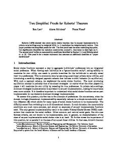
Results and Discussion 5.1 Analyzing Hudson’s coalescent algorithm In this section, Hudson’s coalescent algorithm is analyzed probabilistically based on reference [3]. Correlation of time to MRCA of two genes with two loci are explained in details in [12] and [13]. Consider two genes with two loci. A and a are the alleles of the first gene and B and b are the alleles of the second gene. Different events which can occur in Hudson’s algorithm are illustrated in a state machine in Figure 5.1. A state machine consists of different states which a process (algorithm) can have. In the state machine illustrated in Figure 5.1, probability of going to the next node only depends on the present node; This is the characteristics of a Markov processes. Therefore this process (Hudson’s coalescent algorithm) is a Markov process. For a single locus, it is known (see chapter 3) that the probability distribution of the TMRCA of that locus is exponential. Therefore one can get:
p(τ = x) = e−x
(5.1.1)
< τ >=< τa >=< τb >= 1
(5.1.2)
Thus:
For a Markov process, one can use master equation to find the probability distribution
40
CHAPTER 5. RESULTS AND DISCUSSION
State’s number
¤,¤
ab,AB aB,Ab
1
5
1
Start state
1
1
R a-,-b,AB ab,A-,-B aB,A-,-b Ab,a-,-B
2
2 a¤,A¤ ¤b,¤B
4
4
R/2
2 a-,-b,A-,-B
3
Figure 5.1: State machine for Hudson’s coalescent algorithm
over different states. Master equation is: X X ∂ Pi (t) = wj→i Pj (t) − wi→j Pi (t) ∂t j j
(5.1.3)
Where wi→j is the transition rate from state i to j, Pi (t) is the probability of being in state i at time t and: Mij = wi→j (1 − δij ) − δij
X
wk→i
(5.1.4)
k
Where: δij = 0 if i = j and δij = 1 if i 6= j. Thus one can get: ∂ Pi (t) = M P ∂t
(5.1.5)
P (t) = eM t P (0)
(5.1.6)
And finally:
Equation (5.1.6) gives the probability matrix of being in each state at time t. With the help of this equation one can calculate the probability of going from one node (state) to another node (state) of the state machine.
41
CHAPTER 5. RESULTS AND DISCUSSION
After finding the probability matrix of the state machine (Equation (5.1.6)), one can calculate the correlation of two loci (x stands for the first gene and y stands for the second gene): Z < τx(ij) τy(ij) >=
Z
∞
dτ1 0
Z
∞
∞
(dτ2 )τ1 τ2 P rob(BrokenLinkage) + τ1
0
dτ1 τ12 P rob(Linkage) (5.1.7)
w can be calculated from the state machine as follows: 0 1 0 0 R 0 4 0 w = 0 1/2 R 0 0 0 2 2 0 1 0 0 1
0
0 0 0 1
From (5.1.4) and (5.1.8) M can be computed as follows: −1 − R 1 0 R −3 − 1/2 R 4 M = 0 1/2 R −6 0 2 2 1 0 0
(5.1.8)
0
0
0 0 0 0 −1 0 1 1
(5.1.9)
After calculating M , P rob(Linkage) and P rob(Broken Linkage) can be calculated: P rob(Linkage) = U1T eM t U1
(5.1.10)
P rob(BrokenLinkage) = U2T eM t U1
(5.1.11)
Where: U1T = (1, 0, 0, 0, 0) and U2T = (0, 2, 2, 0, 0) From 5.1.8 and 5.1.11 and 5.1.7 one can conclude: Z < τx(ij) τy(ij) >=
0
∞
Z dτ1 τ12 U1T eM t U1 +
Z
∞
∞
dτ1 0
42
τ1
(dτ2 )τ1 τ2 U2T eM t U1
(5.1.12)
CHAPTER 5. RESULTS AND DISCUSSION
s)
Figure 5.2: Correlation of genes in Hudson’ coalescent algorithm
From equation (5.1.1) one knows < τ >= 1
(5.1.13)
. Finally from (5.1.12) and (5.1.13) one can get an equation for the correlation of two genes with two loci [12]: ρ(τx(ij) τy(ij) ) =
R + 18 R2 + 13R + 18
(5.1.14)
Correlation of genes in Hudson’s coalescent algorithm is also calculated based on the computer simulation. In Figure 5.2 correlation of genes based on the theoretical calculation and the computer simulation are illustrated. As shown, the two plots match perfectly.
5.2 Analyzing McVean’s simplified coalescent algorithm In McVean’s simplified coalescent algorithm, coalescence between lineages with no overlapping ancestral material is not allowed [7]. Therefore one can modify the state machine in Figure 5.1 and construct a new state machine that shows how the McVean’s algorithm works probabilistically. The state machine for McVean’s simplified coalescent algorithm is illustrated in 43
CHAPTER 5. RESULTS AND DISCUSSION
State’s number
¤,¤
1
5
ab,AB
1
Start state
R
1 a-,-b,AB ab,A-,-B
2
2 a¤,A¤ ¤b,¤B
R/2
4 2 a-,-b,A-,-B
3
Figure 5.3: State machine for McVean’s simplified coalescent algorithm
Figure 5.3. As shown in Figure 5.3, there is no edge (connection between nodes) from the node 2 to the node 1. Also there is no edge from the node 4 to the node 2 which is caused by the modification (coalescence between lineages with no overlapping ancestral material is not allowed) that McVean did in Wiuf’s coalescent algorithm. It is of interest to find the probability matrix for McVean’s coalescent algorithm. w can be calculated from the state machine as 0 0 R 0 w = 0 1/2 R 0 2 1 0
44
follows (see (5.1.7)): 0 0 0 0 0 0 0 0 0 2 0 0 0 1 1
(5.2.1)
CHAPTER 5. RESULTS AND DISCUSSION
1 0.9 0.8
Correlation
0.7 0.6 0.5 0.4 0.3 0.2 0.1
0
20
40
60
80
100
Figure 5.4: Correlation of genes in McVean algorithm, R = 5 (recombination rate between two ends)
Hence one can get:
M =
−1 − R
0
0
R
−2 − 1/2 R
0
0
1/2 R
−2
0
2
2
1
0
0
0
0
0 0 0 0 −1 0 1 0
(5.2.2)
Then one can use M in the equation (5.1.13) and calculate the correlation of two genes with two loci in McVean’s algorithm [7]: ρ(τx(ij) τy(ij) ) =
1 R+1
(5.2.3)
In Figure 5.4 correlation of genes based on the theoretical calculation and the computer simulation are illustrated. As shown in the picture, there is a considerable difference in correlation of two genes with two loci in Hudson’s coalescent algorithm in comparison to McVean’s simplified coalescent algorithm.
45
CHAPTER 5. RESULTS AND DISCUSSION
5.3 Analyzing Marjoram’s simplified coalescent algorithm In Marjoram’s simplified coalescent algorithm, coalescent between lineages with no overlapping ancestral material is allowed in some special cases. If a recombination happens between two loci of a gene in step i, in the next step, (i + 1), those recombined loci can coalesce again. This rule can generate two new properties. 1. Start from state 1 in Figure 5.3. Assume the next step is a recombination (state 2). In Marjoram’s algorithm the next step can be state 1. This means the recombined loci can coalesce again. 2. Start from state 2 in Figure 5.3. Assume the second step is a recombination (state 3). Two loci in a same gene in step 4 can coalesce together only if they are recombined in the previous state (i.e. a−, −b, A−, −B can coalesce and make ab, A−, −B only if the previous step was a recombination between a and b). To add the first property to the state machine shown in Figure 5.3, it is sufficient to add an edge from state 2 to state 1. One faces difficulty to add the second property to the sate machine in Figure 5.3, because going from state 3 to state 2 does not depend only on state 3. This means the new state machine will not be Markovian anymore. To have an approximate probabilistic description for Marjoram’s algorithm, one can only consider the first proposition. If one only consider the first property then the state machine in Figure 5.5 can be constructed. Note: In this approximation, it is assumed that the second proposition never happens. Note: It is not so clear how exactly Marjoram’s algorithm works. Only an approximation is presented in this thesis. Analyzing Marjoram’s algorithm more in details is considered as a future work.
46
CHAPTER 5. RESULTS AND DISCUSSION
State’s number
1
5
¤,¤
ab,AB
1
Start state
1
R
1 a-,-b,AB ab,A-,-B
2
2 a¤,A¤ ¤b,¤B
R/2
4 2 a-,-b,A-,-B
3
Figure 5.5: Marjoram model
w can be calculated from the state machine as 0 1 R 0 w = 0 1/2 R 0 2 1 0 Thus:
follows (see (5.1.7)): 0 0 0 0 0 0 0 0 0 2 0 0 0 0 0
M =
(5.3.1)
−1 − R
1
0
R
−3 − 1/2 R
0
0
1/2 R
−2
0
2
2
1
0
0
0
0
0 0 0 0 −1 0 1 0
(5.3.2)
Then w can be used in equation (5.1.13) and the correlation of two genes with two loci can be calculated (approximately) in Marjoram’s algorithm: ρ(τx(ij) τy(ij) ) =
R2
47
6+R + 5R + 6
(5.3.3)
CHAPTER 5. RESULTS AND DISCUSSION
Correlation of genes (Two gene) R = 5 (Recombination rate between two ends) 1 Corr(Tx,Tx+y), based on computer simulation Corr(Tx,Tx+y), based on theoretical calculation
0.9 0.8
Correlation
0.7 0.6 0.5 0.4 0.3 0.2 0.1
0
20
40
60
80
100
Figure 5.6: Correlation of genes in Marjoram’s algorithm, R = 5 (recombination rate between two ends), Sample size = 105
In Figure 5.6 correlation of genes based on the approximate theoretical calculation (equation (5.3.3)) and the computer simulation are illustrated. As shown, the approximation plot is rather close to the plot obtained by the computer simulation. Figure 5.10 demonstrate that for the correlation of two genes with two loci, Marjoram’s algorithm is more accurate than McVean’s algorithm.
5.3.1
Verifying the computer programs
It is essential to verify the validity of the computer programs which are used in this thesis. For Hudson’s algorithm and McVean’s algorithm this can be done by comparing the plots of correlation of two genes with two loci based on the theoretical calculation Vs. computer simulation (see Figure 5.1 and Figure 5.3). For Marjoram’s algorithm there is no accurate formula to calculate the correlation of two genes with two loci. Therefore some of the statistical parameters calculated by Marjoram in their article (see [6]) are compared to the same statistical parameters calculated by the computer program implemented in this thesis. One of these parameters is the mean height of the ith tree moving from the start of the
48
CHAPTER 5. RESULTS AND DISCUSSION
1 Marjoram
0.9
McVean 0.8
Correlation
0.7 0.6 0.5 0.4 0.3 0.2 0.1
0
20
40
60
80
100
Figure 5.7: Correlation of genes in Marjoram’s algorithm (Comparison of different models), R = 5 (recombination rate between two ends). R = 5
gene (left side) to the end of the gene (right side). Figure 5.8 and Figure 5.9 illustrate the comparison of the estimated parameters. These figures show that the computer program from this thesis generate almost the same results to the results that Marjoram’s computer program generates. Figure 5.8 and Figure 5.9 also show that the height of the ith tree in Marjoram’s algorithm is closer to Hudson’s algorithm in comparison to McVean’s algorihtm.
5.4 Relation of mutations and correlation of genes It is of interest to calculate the correlation of genes from the correlation of SNPs of those genes. The following equation is suggested for this purpose [3]: Consider Sy as the number of SNPs in a small part of a gene (a bin) that starts from the position y in a gene with the length L. Therefore L stands for a bin size. In this equation Lc is a gene’s length and n is the number of the genes.
49
CHAPTER 5. RESULTS AND DISCUSSION
i 1 2 3 4 5 6 7 8 9 10
Hudson’s algorithm 1 1.68 2.06 2.39 2.68 2.95 3.19 3.44 3.67 3.92
McVean’s algorithm 1 1.75 2.11 2.33 2.47 2.57 2.65 2.72 2.79 2.84
Marjoram’s algorithm 1 1.68 2.08 2.40 2.66 2.90 3.12 3.33 3.54 3.69
Marjoram’s algorithm implemented in the present thesis 1 1.68 2.08 2.40 2.66 2.90 3.12 3.33 3.53 3.67
Figure 5.8: Mean height of the ith tree for different coalescent algorithms for R = 1. The first, the second and the third column of this table is copied from reference [6] , (Sample size = 10000).
i 1 2 3 4 5 6 7 8 9 10
Hudson’s algorithm 1 1.41 1.63 1.75 1.81 1.87 1.89 1.91 1.93 1.94
McVean’s algorithm 1 1.51 1.76 1.88 1.94 1.97 1.99 1.99 1.99 2.00
Marjoram’s algorithm 1 1.41 1.64 1.77 1.85 1.90 1.93 1.95 1.97 1.98
Marjoram’s algorithm implemented in the present thesis 1 1.41 1.64 1.77 1.85 1.90 1.93 1.94 1.95 1.97
Figure 5.9: Mean height of the ith tree for different coalescent algorithms for R = 100. The first, the second and the third column of this table is copied from reference [6] , (Sample size = 10000).
50
CHAPTER 5. RESULTS AND DISCUSSION
Correlation of SNPs R = 5 ,Two genes 1 Corr(Sx,Sx+y), based on computer simulation Corr(Tx,Tx+y), based on theoretical calculation
0.9
Correlation
0.8 0.7 0.6 0.5 0.4 0.3 0.2
0
20
40
60
80
100
Figure 5.10: Correlation of SNPs in Hudson’s algorithm (R = 20, Bin size = 100, Gene length = 105 )
Correlation(τy(ij) , τ(y+x)(ij) ) ≈
Sy Sy+x − Sy
2
2
(5.4.1)
Sy(ij) S(y+x)(ij)
(5.4.2)
Correlation(Sy(ij) , S(y+x)(ij) ) ≈ Correlation(τy(ij) , τ(y+x)(ij) )
(5.4.3)
Sy2 − Sy − Sy
Where: n
Sy Sy+x =
−x−L i−1 LcX
XX 2 n(n − 1)(Lc − x − L) i=2 j=1
y=1
Thus for two gene one can conclude:
One of the benefits of equation (5.4.3) is to check if the mutations are correctly implemented in a computer program. Results from the computer simulation are illustrated in Figure 5.10.
5.5 Mosaic structures Correlation of genes was used in the last section to compare different coalescent algorithms. It is of interest to find another way to compare different coalescent algorithms. In the following section, Mosaic structures are presented and discussed for this purpose: 51
CHAPTER 5. RESULTS AND DISCUSSION
TA CACGCA TCTC ... CCCA GGT AGCTC ... CCCACGT A TCTC
Figure 5.11: Constructing Mosaic structures.
Group A
1
2
3
1
2
3
1
2
3
Group (B)
1
2
3
Figure 5.12: Mosaic structures for two sites.
Consider three genes (or segments of genes) with the same length. To obtain Mosaic structures from these genes one should start from the left sides of the genes and move to the right. If in one locus one site is different from the others, a black square will be chosen in the same position of its Mosaic structure. If all the sites of a locus are identical, the locus should be ignored. This procedure is illustrated in Figure 5.11. One can always consider the left up side of the Mosaic structure as black because the order of the selected is not important; This means that a gene will be selected as the first row of the Mosaic structure if the first non-identical locus appears on it. To shed more light on the Mosaic structures, genealogy of each locus in a Mosaic structure can be explored. Consider one locus in a Mosaic structure (one column) with infinite site model as the model of mutation. There are four possible positions for a mutation on the genealogy of three selected genes which is illustrated in Figure 5.12. Consider Mosaic structures of two sites. For these kinds of Mosaic structures, as illustrated in Figure 5.12, one can categorize Mosaic structures into two different groups. These groups
52
CHAPTER 5. RESULTS AND DISCUSSION
0.8 Hudson’s Algorithm McVean’s Algorithm
0.7
Marjoram’s Algorithm
Frequency
0.6 0.5 0.4 0.3 0.2 0.1 0 10
1
10
2
10
Log(x*102) 10
Figure 5.13: Frequency of Mosaic structures for two sites, (R = 20, Bin size = 100, Gene length = 104 )
can be interpreted as follows: Group A: Genes where both two mutations are in the same gene. Group B: genes where non of the mutations are in the same genes. Probability of observing group A is two times more than probability of observing group B. Therefore one can conclude that in the absence of recombination: P (Group A) = 2/3 and P (Group B) = 1/3. In Figure 5.13 the frequency of Mosaic structures for two sites are illustrated, based on the computer simulation, in Hudson’s algorithm. As shown in the figure, when the recombination rate is almost zero, the probability of group A is almost twice more than the probability of group B. When the recombination rate (recombination rate between two ends of the gene) becomes higher, the frequency of the Mosaic structures tends to 1/3. This means that recombination destroys the correlation of genes that arises from the linkage between genes. Therefore for the high recombination rate (comparison between a site at the start of the gene with a site at the end of the gene) the frequency of all Mosaic structures are equal. The potability of each group will be 1/3 because there are 3 different possibilities for each Mosaic structure. 53
CHAPTER 5. RESULTS AND DISCUSSION
Group A
Group B
Group C
Group D
Figure 5.14: Mosaic structures for three sites.
One can consider the Mosaic structures for three sites. In Figure 5.14 the different Mosaic structures for three sites are illustrated. When the recombination rate is zero (or close to zero), the Mosaic structures that have higher correlation in their patterns have a higher chance to exist. Therefore on can conclude: P (Group A) > P (Group B) > P (Group C) > P (Group D). The results of the computer simulation on the frequency of three sites Mosaic structures are illustrated in Figure 5.15. As it is shown in this figure, when the recombination rate goes higher, the frequency of all Mosaic structures becomes equal (The probability of each group will be 1/9 because there are 9 different possibilities for each Mosaic structure). One can compare the frequency of Mosaic structures of different coalescent algorithms. The comparison is done via computer simulation for two and three sites Mosaic structures. The results of computer simulation are illustrated in Figure 5.13 for two sites and in Figure 5.16 for three sites. Figure 5.16 shows that the results from Marjoram’s coalescent algorithm is closer to Hudson’s coalescent algorithm in comparison to McVean’s coalescent algorithm.
54
CHAPTER 5. RESULTS AND DISCUSSION
Group A
Group B
Group C
Group D
Figure 5.15: Frequency of Mosaic structures for three sites.
Hudson’s Algorithm McVean’s Algorithm Marjoram’s Algorithm
Figure 5.16: Frequency of Mosaic structures for three sites.
55
CHAPTER 5. RESULTS AND DISCUSSION
5.6 Conclusion Many efforts have been done to make the Hudson’s coalescent algorithm faster. The simplified coalescent algorithms which were introduced by McVean and Marjoram run faster than Hudson’s algorithm. The size of the genealogy generated from Hudson’s algorithm is dependet on recombination rate between two ends of the genes. This dependency makes the genealogy bigger and the calculation slower when the recombination rate increases. In both McVean and Marjoram’s simplified coalescent algorithm the size of the genealogy generated with the algorithm is independent of the recombination rate. The independency of the size of the genealogy from the recombination rate improves the speed of the computer program implemented from the algorithm. Although McVean and Marjoram’s simplified coalescent algorithms run faster, statistical results generated from them are different from statistical results generated by Hudson’s algorithm. Comparison of the correlation of genes and the frequency of Mosaic structures between McVean and Marjoram’s algorithms show that Marjoram’s algorithm generates statistical results which are closer to Hudson’s coalescent algorithm.
56
Appendix A
Computer programs description (Hudson’s algorithm) A.1 Program description, Hudson’s model for two genes Program description Hudson’s algorithm with recombination [With mutation]. Computer Language C++ Number of genes which the program can use Two genes. Gene type Continuous and discrete. Computer Language C++ Capabilities Calculate the correlation of two genes with two loci, Calculate the correlation of SNPs Note : If discrete genes are desired, one should consider fixed points as cutting points. Each gene is considered as an interval between zero and one.
A.2 Data structures and important variables Three kinds of data structures are used in this program (Node, MRCA, intervals).
57
APPENDIX A. COMPUTER PROGRAMS DESCRIPTION (HUDSON’S ALGORITHM)
intervals This data structure is used to save each part of the gene ([0,1]) which exists in each step. MRCA This data structure is used to save information about the most recent common ancestors which are found in each step of the algorithm. node This is the main data structure which is used in this program. Each node in the coalescent tree is of this type. Each node contains information about both genes, So each of these nodes are connected to two data structure of ’intervals’ type. ’Node’ data structure is illustrated in Figure A.2. There are some constants and variables in this program which have an important roles:
max generation Indicate the number of runs for each recombination rate. Accuracy Indicate the number of sample points to find the pairwise correlation. (Number of division of interval [0,1]). RecomStart The first recombination rate to consider. RecomEnd The last recombination rate to consider. R step The step between each recombination rate. t mrca This array saves the TMRCA of each sample point for each generation. corr m The correlation matrix of sample points. teta Mutation rate. DNA Length The length of the gene considered in the program. sample size Size of sampling of SNPs. move Distance considered between each sample (to compute SNPs). 58
59
Before
start
next end
start
next end
Next_interval_1
start
next end
start
next end
Interval data structure
Node data structure
T
start
Next_interval_2
Null
end_int_1 end_int_2
next end
Next
next : Pointer to next interval data structure. end : End of the interval. start : Start of the interval.
Next
Next_interval_1
end_int_1 end_int_2 Before : Pointer to previous node. Next : Pointer to next node. T : time end_int_1: Pointer to the last node of data structure which Next_interval_1 pointer points to it. end_int_2: Pointer to the last node of data structure which Next_interval_2 pointer points to it. Next_interval_1:Pointer to interval data structure. Next_interval_1:Pointer to
Next_interval_2
T
Before
Null
APPENDIX A. COMPUTER PROGRAMS DESCRIPTION (HUDSON’S ALGORITHM)
Next
Next_interval_2
Next_interval_1
end_int_1 end_int_2
T
Before
APPENDIX A. COMPUTER PROGRAMS DESCRIPTION (HUDSON’S ALGORITHM)
DNA1 and DNA2 Save the gene data (zero if it is not mutated and one if it is mutated). SNP patterns Save information about SNPs in each generation. corr SNP The correlation matrix of SNPs.
A.3 Description of the functions add node : Add a new node to ’node’ data structure. add int node : Cut one gene and make two new genes from it. add coal node : Make a new coalesced gene from two chosen gene. find MRCA : Find the MRCA part of two genes. cutting point : Generate a cutting point (It is possible to change this part to have a discrete version of genes). search m : This function can be called from find MRCA function to check if the MRCA is not found before. exp rand : Generate a random number from exponential distribution function. This is inspired from reference [2]. free memory nodes : Delete ’node’ data structure. free memory MRCA : Delete ’MRCA’ data structure. time to mrca : Find time to most recent common ancestor of sample points. free child memory : This function can be called from free memory nodes to delete branches of ’node’ data structure. find corr x: Find the correlation matrix for different recombination rates in order to their distance. add mutation: Add mutation. del node: Delete a node. end pro: Check if all part of the gene has found their MRCAs before reaching GMRCA. add m: Add a node to MRCA data structure. count SNP : Count the number of SNPs.
60
APPENDIX A. COMPUTER PROGRAMS DESCRIPTION (HUDSON’S ALGORITHM)
find corr SNP: Find the correlation of SNPs. Initialize nodes: Assign initial values for the node data structures. recombination: Recombination event. coalescent: Coalescent event. save results: Save the correlation results in a data file. poidev: Generate a random number (From poisson distribution).
A.4 Program description, Hudson’s model for three genes Program describtion Hudson’s algorithm with recombination [With mutation]. Computer Language c++ Number of genes which the program can use Three genes. Gene type Continuous and discrete. Computer Language C++ Capabilities Calculate the frequency of Mosaic structures for two and three sites. The structure of the program is the same as Hudson model for three individuals. Some additional functions are added in this program: count SNP : Count the Mosaic structures for two sites. count SNP 3 : Count the Mosaic structures for three sites.
61
Appendix B
Computer programs description (McVean and Marjoram’s algorithm) B.0.1
Mcvean’s algorithm
Program description McVean’s algorithm [With mutation]. Computer Language C++ Number of genes which the program can use Two and three genes. Gene type Continuous and discrete. Computer Language C++ Capabilities Calculate the correlation of two genes, Calculate the correlation of SNPs, Calculate the Mosaic structures frequency (for two and three sites). In this program node data structure is consist of the information about the children of that node, parent and time to that node. Instead of linked list, arrays are used in this program. Description of some important functions: (Other function are explained in Appendix A.) find time: Find the point that the floating line should coalesce to the tree. (As it is explained in the algorithms in Chapter 5). 62
APPENDIX B. COMPUTER PROGRAMS DESCRIPTION (MCVEAN AND MARJORAM’S ALGORITHM) update tree: Make a new tree from the old tree.
The main parts of the program for two and three genes are the same.
B.0.2
Marjoram algorithm
The main parts of this program is the same as McVean program. Only update tree function is different.
63
Bibliography [1] Hein, Jotun and Schierup, Mikkel H., (2005), Gene genealogies, variation and evolution, a primer to coalescent theory, Oxford university press. [2] William, H. Press and Brian, P. Flannery and Saul, A. Teukolsky and William, T. Vetterling, (1992), Numerical Recipes in C: The Art of Scientific Computing, Scientific Computing, Cambridge University Press. [3] Eriksson, Anders and Mehlig, Bernhard, (2004), Genetic-history correlation and population structure, Physical Biology 1, 220-228. [4] Ewens, Warren J., (2004), Mathematical Population Genetics, Springer. [5] Hartl, Daniel L. and Clark, Andrew G., (2007), Principles of Population Genetics, Sunderland, Mass. : Sinauer Associates, cop. [6] Marjoram, Paul and Wall, Jeff D., (2006),Fast ”coalescent” simulation, Published online ,doi:10.1186/1471-2156-7-16. [7] McVean, GAT and Cardin, NJ, (2005),Approximating the coalescent with recombination. Phil Trans R Soc B;360:13871393 [8] Wiuf, C and Hein, J., (1999),Recombination as a Point Process along Sequences. Theor Popul Biol,55:248259. [9] Kingman, JFC, (1982),On the genealogy of large populations. J Appl Prob.;19A:2743. [10] Watterson, G. A., (1974),The sampling theory of selectively neutral alleles. Adv. Appl. Probab. 6:463-488.
64
BIBLIOGRAPHY
[11] Watterson, G. A., (1976),The stationary distribution of the infinitely-many neutral alleles diffusion model. J. Appl. Probab. 13:639-651. [12] Hudson, R. R., (1983),Properties of a neutral allele model with intragenic recombination. Theor. Popul. Biol. 23: 18320. [13] KAPLAN, N. and HUDSON, R. R., (1985),The use of sample genealogies for studying a selectively neutral m-loci model with recombination. Theor. Popul. Biol. 28:382-396 [14] Hartl, Daniel L., (2000),A Primer of Population Genetics, Third Edition. Sinauer Associates,Inc. [15] Nordborg,M, (2000),Coalescent Thoery. Department of Genetics, Lund University. [16] Mendel, G., (1866),Versuche ber Pflanzen-Hybriden. Verh. Naturforsch. Ver. Brnn 4: 347 (in English in 1901, J. R. Hortic. Soc. 26: 132) [17] Waterman, Michael S., (1995),Introduction to Computational Biology Maps, Sequences and Genomes. CRC Press. [18] Russell, Peter J., (2002),Genetics. Benjamin-Cummings Publishing Company.
65