A Low SAR, Five-Band MEMS Switched PIFA For Mobile Phones K. R. Boyle*(1), P. G. Steeneken(2) (1) NXP Semiconductors, Redhill, England (2) NXP Semiconductors, Eindhoven, The Netherlands Introduction Future mobile Receive Transmit phones will be required to operate GSM1900 in the five bands GSM850 UTRA V UTRA II shown in Fig. 1. USA Operation is only 869 1850 1930 required in one band 824 to to to to 1910 1990 849 894 at a time, so a small GSM900 GSM1800 UTRA I antenna can be UTRA III UTRA VIII (UMTS FDD) switched to operate Europe over a number of 880 925 1710 1805 1920 2110 narrow bands. to to to to to to 915 960 1785 1880 1980 2170 However, to achieve this over a total Fig. 1 Common cellular frequency bands used in Europe and the USA (MHz). All bands are also widely used worldwide bandwidth of approximately one octave without significantly reducing efficiency, low loss switches are required. A planar inverted F antenna (PIFA) that is switched using capacitive microelectromechanical systems (MEMS) switches - fabricated in the industrialized NXP Semiconductors PASSITM process [1] - is reported D C here. Although MEMS switched antennas have been reported previously [2], [3], none have been shown to be A B capable of operation over five mobile phone frequency PIFA bands and none have been reconfigurable using only external components (i.e., not on the antenna itself). Switching on the antenna is problematic, since isolation must be maintained and because a minimum number of (relatively large) connections between the antenna and the supporting PCB are desirable in a mobile phone. Also, the technology PCB used to fabricate the antenna is often incompatible with circuit manufacturing techniques such as reflow soldering.
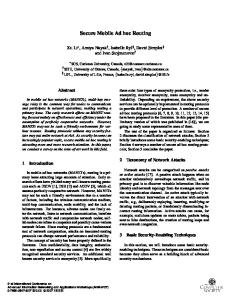
Antenna Geometry The antenna has dimensions 40 x 12 x 8mm, as shown in Fig. 2, and the PCB has dimensions 40 x 100 x 0.8mm and is metalized on the back surface to provide an RF ground. The antenna has a single slot that is located in a position where it is unlikely to be perturbed when the phone is held [4], [5]. The antenna is connected to the RF circuitry at points A, B, 1-4244-0878-4/07/$20.00 ©2007 IEEE
2833
Fig. 2 MEMS switched PIFA and PCB
C and D and, for ease of manufacturing, all circuitry is on the PCB rather than the antenna. The antenna is fed at point D and shorted to ground at point B. The impedance at point A controls the antenna resonant frequency. With a high impedance at this point (i.e., a MEMS device in the OFF state), the slot in the antenna acts as an inductor, reducing the resonant frequency and allowing operation in the low frequency band, 824960MHz. In this condition the antenna resistance is transformed up by the provision of a low impedance at point C (i.e., a MEMS device in the ON state connected to ground). A double-tuning capacitor is also introduced at the feed when point C is switched to ground in order to tune out shunt inductance introduced and, hence, to extend the bandwidth. With a low impedance at point A, the inductance of the slot is removed and the antenna resonates at a high frequency. In this mode the slot provides an upwards impedance transformation, hence point C is switched to a high impedance. In the high frequency mode, the resonant frequency can be shifted slightly higher with capacitive loading (i.e., additional MEMS devices) at point A.
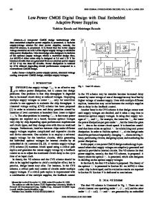
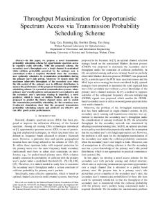
Simulated Results The antenna has four operational modes, the simulated impedances of which are shown in Fig. 3. All modes, with the exception of UTRA Band 1, have an S11 of –6dB or better (referred to 50 Ohms). The resonant frequency of the 19202170MHz mode is deliberately designed to be too high, to allow DC tuning to a lower frequency (when an S11 of –6dB is achievable). The SAR in the high frequency mode can be significantly less than that of conventional antennas. This is because Fig. 3 Simulated S11: 824-960MHz (black, the entire antenna is used in all bands, solid), 1710-1880MHz (grey, solid), 1850whereas for conventional antennas an 1990MHz (black, dashed), 1920-2170MHz additional local resonance is often (grey, dashed). employed to give extended high frequency bandwidth. This is illustrated in Fig. 4 (a), where the SAR of a tri-band conventional antenna of dimensions 40 x 22.2 x 8mm is simulated using the procedure outlined in [6]. A parasitic element is used to extend the high-band frequency range: the antenna covers the 880-960MHz and 1710-1990MHz bands. It can be seen that the SAR contours are localized between the driven antenna and the parasitic element. The maximum SAR is 13.4 W/kg with a 1cm3 averaging volume and an input power of 1W. Fig. 4 (b) shows contours for the MEMS switched antenna. Clearly, the SAR contours are less localized and the maximum SAR is significantly less at 9.3 W/kg, despite the fact that the MEMS switched antenna has a volume that is approximately only 55% of that occupied by the conventional antenna. The SAR in the low-band is approximately the same for MEMS switched and conventional designs.
Implementation and Measurements A photograph of the MEMS switched antenna is shown in Fig. 5. The antenna is fabricated from a polyimide flexible PCB that is first bonded to a rigid GETEK PCB and 2834
then folded over a Rohacell block. The antenna/PCB combination is fed via a coaxial cable at a central point on the PCB to avoid excessive perturbation from the feeding cables [7]. A microstrip line runs between this point and the antenna feed. 2 4 6 8 10 12
8 6
Driven antenna
4
MEMS Switched antenna
Parasitic
2 4
4
6 8
(a) (b) Fig. 4 Simulated SAR at 1845MHz (W/kg with a 1cm3 averaging volume and an input power of 1W): (a) conventional antenna, (b) MEMS switched antenna The capacitive MEMS switches are placed on two dies mounted close to points A and D. To compensate for device and assembly uncertainties, MEMS devices with slightly varying layouts are implemented. The MEMS devices are unpackaged and, hence, susceptible to sticking. Because of this, all tests that involve actuation of the devices are performed whilst blowing nitrogen over them. Measured results are shown in Fig. 6. In the UTRA band V/VIII mode, the S11 is below –6dB between 765-950MHz, showing that a wide bandwidth resonance is obtained. The centre frequency is somewhat lower PCB feed than that simulated at 830MHz, but the bandwidth is DC bias lines approximately 180 MHz (fractionally, 22%), which is slightly better than simulated. For the high frequency bands, the resonant frequencies are D. Feed somewhat higher than simulated. The –6dB C. Switched connection A. Switched connection bandwidths are 1930(for impedance matching) (for frequency tuning) 2062MHz, 1941-2071MHz and B. Short to ground 2005-2117MHz for the UTRA Fig. 5 MEMS switched PIFA and PCB bands III, II and I respectively. 2835
These bandwidths are less than simulated. However, this is largely due mismatch. With series inductive matching, bandwidths of approximately 300MHz – slightly higher than those simulated - can be achieved. Resonant frequency shifts are clearly observed in the high frequency modes, though the magnitudes of the shifts are less than simulated. The differences between simulation and measurement are attributed predominantly to uncertainties in the capacitance density of the MEMS devices and long (unsimulated) bond wires.
Conclusions
0
-5
S11 (dB) -10
-15 0.6
0.8
1
1.2
1.4
1.6
Frequency (GHz)
1.8
2
2.2 9
x 10
Fig. 6 Measured S11 (below –6dB): 765-960MHz (black, solid), 1930-2062MHz (black, dotted), 19412071MHz (light grey, solid) and 2005-2117MHz (dark grey, solid). Low and high frequency results measured with slightly different MEMS devices.
A five-band MEMS switched antenna, utilizing capacitive MEMS switches is demonstrated. The measured prototype confirms that the antenna is capable of operating in several modes over a bandwidth of greater than one octave. It also confirms that wide bandwidths are feasible (in each mode) from an antenna that is smaller than conventional. Simulations show that superior SAR performance is possible at high frequencies. In the future, the use of directly soldered, packaged MEMS with improved capacitance density tolerances, will lead to closer agreement between simulations and measurement.
References [1] [2] [3] [4] [5] [6] [7]
J.T.M. van Beek et. al., “MEMS for wireless communication: application, technology, opportunities and issues”, in Proc. MEMSwave2006, 27-30 June, 2006. J. Kiriazi, H. Ghali, H. Ragaie, H. Haddara, “Reconfigurable dual-band dipole antenna on silicon using series MEMS switches”, in Proc. IEEE Antennas and Propagation Soc. Int. Symp., vol. 1, 2003, pp. 403 – 406. P. Panaia et. al., “MEMS-based reconfigurable antennas”, in Proc IEEE Int. Symp. on Industrial Electronics, vol. 1, 2004, pp175 – 179. K.R. Boyle and L.P. Ligthart, “Radiating and Balanced Mode Analysis of PIFA Antennas”, IEEE Trans. Antennas and Propagat., vol. 54, no. 1, pp. 231 – 237, Jan. 2006. K.R. Boyle and L.P. Ligthart, “Radiating and Balanced Mode Analysis of User Interaction with PIFAs”, in Proc. IEEE Antennas and Propagation Soc. Int. Symp., vol. 2B, 2005, pp. 511–514. P.J. Massey, “Finite element simulation of SAR”, presented at IEE Antenna Measurement and SAR Seminar, Loughborough University, 28-29 May, 2002. P.J. Massey and K.R. Boyle, “Controlling the effects of feed cable in small antenna measurements”, in Proc. 12th Int. Conf. on Antennas and Propagation, 2003, pp. 561 -564.
2836