The 3rd International Conference on ″Computational Mechanics
and Virtual Engineering″″ COMEC 2009 29 – 30 OCTOBER 2009, Brasov, Romania
NEW TESTING DEVICES OF INTUMESCENT COATINGS Péter Dani1, Károly Jármai2, András Kakucs3, József Farkas4, János Száva5, László Kalmár6, Botond Pál Gálfi7 1
Ph.D, student, Transilvania University of Braşov, Romania,
[email protected] 2 Ph.D, professor, University of Miskolc, Hungary,
[email protected] 3 Ph.D, associate professor, Sapientia University of Tîrgu-Mureş, Romania,
[email protected] 4 Ph.D, professor, University of Miskolc, Hungary,
[email protected] 5 Ph.D, professor, Transilvania University of Braşov, Romania,
[email protected] 6 Ph.D, associate professor, University of Miskolc, Hungary,
[email protected] 7 Ph.D, student, Transilvania University of Braşov, Romania,
[email protected]
Abstract: Based on our studies we have established a new possibility of modelling the behaviour of intumescent fire protective coatings based on the method of finite elements. In this modelling we need some parameters, as the thermal conductivity of the coating. This conductivity depends on the temperature and estate of the coating and in our earlier works we have proposed some simple methods do estimate it. This paper deals with some enhancements of the proposed methods and with some comparative experiments. Keywords: intumescent coating, fire protection, testing device at high temperatures
1. INTRODUCTION In our earlier studies we have been concentrated on the estimation of fire protective behaviour of the intumescent coatings. This behaviour is explained by the appearance of a porous layer on the surface of the protected structural element due to the thermal (pyrolytic) decomposition of the paint. This foam-like layer has a low thermal conductivity, lower than that of the original, unaffected coating and lower than that of the resulting char. The physical and chemical processes during this decomposition are very complicated and they cannot be modelled in an exact manner. Due to this fact, the investigation of the fire protecting coatings is based on the direct observation of some samples, and the simplest way of modelling the intumescent coating is that of characterizing its thermal conductivity with a global λ(T, t) coefficient, that is a function of temperature and time and it encloses the contribution of all the mentioned processes. Because the thickness of the coating is not constant (it is growing during the foam forming) this coefficient is often correlated with the initial thickness or it is given as the Λ(T, t) thermal conductivity of the studied coating. We have tried to elaborate a very simple laboratory equipment and measuring method, using some samples made as metallic bands with a thin coating on both faces (fig. 1.). We expect that this thin coating (after a transient period) behaves as a homogenous layer. This metallic band is heat up by an electrical current (by the Joule-effect), the dissipated power is P = U ⋅ I . This band must be enough long for the limitation of the side effects; its surface is computed using its length L and width W as S = 2 ⋅ L ⋅ W (it has two faces). The heat flux is obtained as ϕ = P / S . Measuring the temperature of the metallic band and on the outer surface of the coating, using the first form of Fourier's law λ is obtained:
ϕ = −λ ⋅
dT dx
→
λ =ϕ⋅
∆T , t
(1)
where the ∆T/t temperature gradient is given as the difference of the temperature between the outer and inner face of the coating divided by its initial thickness. 0
This determination was made on different temperatures, up to 300 .... 350 C , in different states of the coating, and we have obtained λ as a function of the temperature. During the foam forming process at constant temperature, λ had a nearly constant value; its value increases as the foam become carbonized. We have deduced the reaction rate using the length of the time interval with near constant λ.
752
The temperatures were measured using some PT100 sensors and a Fluke IR thermometer. The obtained results were used in finite element modelling of the intumescent coating.
Figure 1: The electric circuit of the experimental apparatus and one of the studied samples We met some problems here: a). in case of thick foam layers these tend to peel off at the edges; in this case the homogeneity of the temperature field is compromised; b). in case of high temperatures the PT100 sensors fail; c). the temperature curves used as thermal load curves in dimensioning refer to the ambient temperature and not to the temperature of the exposed surface, so the α factor of the Newton's cooling law and the ε emissivity have to be determined; d). in our experiments the direction of the heat flux and that of the gas bubbles was the same. In reality the heat penetrates from the outer surface (and not from the inner one, as in case of the electrically heated metallic bands), and the bubbles rise from the depth of the coating to the surface, carrying a certain amount of heat and contributing to the thermo-insulating property of the coating. In many cases ([3], [6]) this contribution is neglected, but we are not sure if reversing the cooler and warmer sides alters the foam forming process or not. We hoped to get answers and solutions using a modified apparatus.
2. THE MODIFIED APPARATUS In its first version, as a response to the a) point of the previous list, we have built a slightly modified apparatus to estimate the thermal conductivity of the intumescent coating. This is based on that used in our earlier experiments, but the metallic band was replaced by a thin-walled metallic tube closed at both ends (as that on the fig. 2). The solution of the b) problem is the replacement of the PT100 sensors with some thermocouples (thermoelements), embedded into the metallic tube or placed on the outer surface of the coating. These thermo-elements have larger measuring interval but lower accuracy than the PT100 sensors.
Figure 2: One of the tube-shaped sample at the beginning of the foam-forming phase Because the sample has a circular symmetry and it has no edges, we can obtain a more homogenous and continuous foam layer that behave as a tube-like thermo-insulator.
753
In this case the heat flux through this tube-like coating is calculated as
Φ =π ⋅
Ti − To ⋅l , δ 1 ⋅ ln o δi 2⋅λ
(2)
where l is the length of the tube, δi is the inner diameter of the tube, δo is the outer diameter of the coating (foam), Ti and To are the temperatures on the inner, respectively on the outer surface of the coating. The Φ flux is equal to the P = U ⋅ I electric power. The measurements have to be done in steady state situations, at constant temperatures, as in the case of metallic bands. Some sample results are presented on the figure 3. On this figure the upper curve is that obtained at a low-rate heating of the sample. The temperature was increased slowly to eliminate as well as possible the transient effects. On this curve we can observe that the heat conductivity increases as the material of coating is melted, but after the beginning of the foam forming it drops to some relatively small values. During the foam-forming process (at a constant temperature, on the lower curve) the value of the thermal conductivity coefficient λ remains near constant and equal of that of the formed carbonized layer (of the char). We have concluded, that the thermal conductivity coefficient has a certain, but not too accentuated variation during the studied process and the benefic effect, the good heat insulator capacity of the coating is due mainly to the important volume growth of the foam.
Figure 3: Some results
To give an answer to the c) problem, supplementary we have measured the ambient temperature too, Ta. Because the (2) flux is dissipated in the surroundings, we can write the following energy balance equation: Φ = S ⋅ [α ⋅ (To − Ta ) + ε ⋅ σ 0 ⋅ (To4 − Ta4 )] ,
(3)
where S is the area of the outer surface of the coating, σ0 is the Stefan-Boltzmann constant. The ε emissivity was determined using the Fluke IR thermometer. This is equipped with a thermocouple etalon: when the temperature obtained using the IR bolometer and a set ε value is equal to that measured by the thermocouple, we can accept that ε value as the good approximation of the real emissivity of the coating (we suppose that it behaves as a "gray" body). The determinations were made on different stages of the coating. We have expected that in the case of dark-colored carbonized coating we will obtain some larger values but in all cases the thermal emissivity coefficient was between 0.8 and 0.85. Having this ε, from (3) we obtain the value of α, a value for still air. We have obtained some values between 7 and 10 W/(m2⋅K).
754
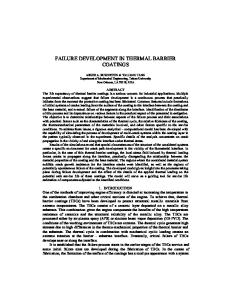
3. HEATING THE OUTER FACE To estimate the effect of reversing the cooler and warmer sides we have built an electric furnace. This is boxshaped with insulated walls fixed on the steel frame, with a window made from thermal-resistant glass that makes possible the visual observation of the processed. This box has an opening on its top. Through this opening we can put in and to take out the samples and the wires of the used thermocouples also are introduced here. This opening during the experiments is covered by a fire-clay block. The shape and the sizes of the furnace are shown in fig. 4. The furnace is heated using some "silit"-bars (made from sintered silicon carbide). The first version was built using four bars with a total power of 3.3 kW and without control of the temperature, but our intention is to enhance it with three-phased heating at higher maximum power and with electronic regulation. The electric heating provides a certain temperature, Ta, but because the heat losses through the walls the Φ flux in (2) won't be equal to the consumed electric power. This flux can be determined only by cooling the tube with air: if the mass flow of the air inside the tube is qm, the temperatures at the entry and leaving cross sections are T1 and T2, respectively, then the heat flux will be Φ = qm ⋅ c p ⋅ (T2 − T1 ) ,
(4)
where cp is the isobaric specific heat capacity of the air. This determination needs the two temperatures and the mass flow.
Figure 4: The sketch of the furnace and its equipped realization
In this scope we have used a modified hot air blower: it was not connected to the 220 V network but its electric motor was supplied using a DC voltage regulator. This makes possible two things: to use it without warming the air (originally its motor was coupled in series with one of the heating resistances) and to have a control over the air flow. This blower was connected to a copper tube equipped with an orifice plate flow meter. This flow meter in fact is a thin obstacle with a central circular orifice; the volumetric flow is obtained by measuring the pressure drop on the orifice plate. The mass flow is obtained by multiplying the volumetric flow with the density of the air, and this density is a function of the pressure, of the temperature and of the humidity of the air. So given, we had to measure not only the pressure drop but the relative pressure and the temperature of the air inside this tube, and the temperature, the humidity and the absolute pressure of the air outside of the tube. Because the tube is made from copper and the pressure drop was only a few mmH2O, these two temperatures were the same due to the high thermal conductivity and low expansion of the air. The cp specific heat it is also a function of the humidity, so we had to calculate this value too. To get all interesting parameters, we have used a differential manometer, a barometer, a combined humidity- and thermometer and some thermocouples in this scope (fig. 5). During the experiments we have observed that the evolution of the coating along the tube was not uniform. We can explain this fact by the variation of the temperature along the tube (in its inside): the air enters at room temperature and as it flows inside the tube it gets warmer and warmer as it accumulates the transmitted heat. So there is a temperature difference between the two ends and the heat transmission (by convective processes) takes place at a variable temperature. The shape of the formed foam coating was slightly conical and not cylindrical. The diameter of the coating was estimated using the photos taken during the experiments (fig. 6.). The effect of the temperature difference between ends can be reduced by increasing the mass flow of the cooling air; in this scope in the future we will use another blower with higher power. If we accept that the temperature increases linearly along the tube, we can compute the value of λ using the mean value of the diameters.
755
Having all measured values, using the formulas mentioned above we have obtained some values of λ near to those obtained in our previous experiments, with direct electric heating of the tube. The values were computed only in the situation when the foam was formed and it was visible in the same stage along the whole tube.
Sample Thermocouple Orifice plate
Blower
Copper tube
Furnace
Differential manometer
Rubber connection
Hygrothermometer
Barometer
Figure 5: The used laboratory apparatus
x mm
20 mm
Figure 6: Estimation of the diameter
4. CONCLUSIONS In the case of tube-shaped samples we have obtained the same values of λ. Both methods have some sources of errors, the first one that of the reversed sense of the heat flow and the second one that of the non uniform temperature field coating and that of the larger number of quantities to be measured and computed, but both methods lead to the same values. Based on these results, we can conclude that the effect of the reversed sense of the heat flow can be neglected, and this fact can be explained by the insignificant contribution of the convective heat transfer beside of the heat conductivity through the foam. The experiments show, that the heat convection can be neglected, as it was supposed in some of the references ([3], [6]). Because these determinations using the furnace are rather difficult, the method with direct electrical heating is preferred, even if the cooler and warmer sides are reversed against the case of a real fire.
756
The proposed method of direct heating has the advantages of the simple laboratory apparatus of determining the parameters of the intumescent coatings. The obtained experimental values can be used in finite element modeling, which offers a general way to analyze structures protected by intumescent coatings against fire.
REFERENCES [1] Melinek, S. J., Thomas, P. H., Heat flow to insulated steel, Fire Safety Journal, 12 (1987), pag.1-8. [2] Wickström, U., Temperature analysis of heavily-insulated steel structures exposed to fire, Fire Safety Journal, 9 (1985), pag. 281-285. [3] Nordtest Method, NT FIRE o21, NORDTEST 1985, Denmark. [4] Pettersson, O., Ödeen, K., Brandteknisk dimensionering, Liberförlag, Stockholm, 1978, pag.181. [5] Cagliostro, D. E., Riccitiello, S.R., Clark, K.J., Shimizu, A.B., Intumenscent coating modeling, Journal of Fire and Flammability, Vol.6 (April 1976), pag.2o5-221. [6] Andersen, Niels E., NORDTEST Project Raport (Influence of heating rate and other parameters on thermal conductivity of intumescents for fire protection of structural steel), Dantest Report, National Institute for Testing and verification of Denmark, 1988. [7] ***- Design manual of the European Recommendation for the Fire Safety of Steel Structures, ECCS 1985. [8] Jármai, K., Iványi, M., Design of steel structures for fire safety, Introduction to the European standards
and their applications at steel structures. Gazdász-Elasztik Kft. Miskolc, 259 p. 2008. ISBN 978-96387738-4-5 (in Hungarian). [9] Kakucs A, Száva J, Dani P, Constantin V, A New Approach to Estimate the Intumescent Coatings’ Quality, MicroCAD 2007.
ACKNOWLEDGEMENT
The research was supported in Romania by Department of European Integration and International Cooperation, National Authority for Scientific Research from Ministry of Education, Research and Innovation, grant number 87/22.08.2008, respectively in Hungary by the National Office for Research and Technology (NKTH) through a bilateral Hungarian-Romanian co-operation (RO 06/2007). This activity is financed by the Research and Technology Innovation Fund. The project number is OMFB-00591/2008. The research was supported also by the Hungarian Scientific Research Fund within the project OTKA T 75678, which is gratefully acknowledged.
757