1062
IEEE TRANSACTIONS ON CIRCUITS AND SYSTEMS—I: REGULAR PAPERS, VOL. 51, NO. 6, JUNE 2004
One-Tap Wideband I/Q Compensation for Zero-IF Filters Péter Kiss, Member, IEEE, and Vladimir Prodanov, Member, IEEE
Abstract—The I/Q imbalance is one of the performance bottlenecks in transceivers with stringent requirements imposed by applications such as 802.11a. The mismatch between the frequency responses of two analog low-pass filters, used, e.g., for channel selection in zero-IF receivers, makes this I/Q imbalance frequency dependent. Usually, frequency-dependent I/Q mismatch is estimated and corrected by adaptive techniques, which are complex to implement and may converge slowly due to noise. In this work, a simple, delay-based I/Q compensation scheme is proposed based on an extensive statistical analysis. Its digital implementation uses only two coefficients, which are tuned by a one-step two-tone error estimation. Simulations show that this hardware-efficient scheme significantly reduces the I/Q imbalance.
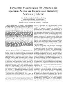
Fig. 1. I/Q leakage in an RX chain.
Index Terms—Complex filters, frequency-dependent I/Q compensation, I/Q filters, I/Q imbalance, sensitivity analysis, wideband I/Q calibration.
I. I/Q MISMATCH IN TRANSCEIVERS
A
simplified linear model of a zero-IF [1], [2] receiver (RX) is shown in Fig. 1. Usually, the RX chain includes an antenna (A), a low-noise amplifier (LNA), a pair of mixers driven by quadrature local-oscillator (LO) signals I( ) and Q ( ), a pair of real low-pass filters (LPFs), a pair of analog-to-digital converters (ADCs) sampled at , and a digital signal processor (DSP) [3]. An orthogonal frequency-division multiplexing (OFDM) DSP, used in 802.11a [4], inherently contains a fast-Fourier transform (FFT) block. A zero-IF transmitter (TX) chain starts with a DSP and is followed by a pair of digital-to-analog converters (DAC), a pair of LPFs, a mixer/LO block, a power amplifier (PA), and an antenna [3]. The main contributors of the RX or TX chain’s I/Q imbalance1 are the gain error ( ) of the mixers, the phase error ) in the LO signals, the gain ( ) and phase ( ) ( mismatch between the LPF’s transfer functions, and, finally, the gain error ( ) between the data converters (ADCs in RX, DACs in TX). The I/Q imbalance contribution of gain and phase errors can be modeled as a two-input two-output linear network with some inter-coupling coefficients [5]. These simple models can be individually applied to each block of mixers/LO, LPFs, Manuscript received June 30, 2003; revised December 18, 2003. This paper was recommended by Associate Editor A. Wang. The authors are with the Department of Communications Circuits Research, Agere Systems, Allentown, PA 18109 USA (e-mail:
[email protected];
[email protected]). Digital Object Identifier 10.1109/TCSI.2004.829233
1Terminology used: I/Q mismatch or I/Q errors cause I/Q imbalance or I/Q leakage.
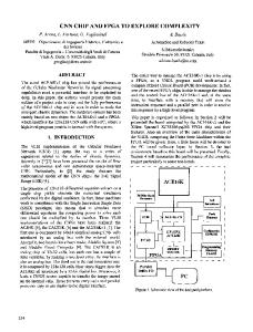
Fig. 2. Concept of I/Q leakage compensation.
and ADCs, as shown on the bottom of Fig. 1. In mathematical terms (1) where , , and are given in Fig. 2. The resulting image rejection ratio (IMR) can be calculated by [5] dB
(2)
A simple graphical derivation of (2) is presented in Appendix I. Detailed analytical calculations can be found in, e.g., [3], [6]–[8]. The concept of I/Q imbalance compensation is straightforward: whatever “leaks” due to I/Q mismatch can be cancelled by deliberately “leaking back” the same amount. To compensate for this I/Q leakage, first, the coefficients of the error mashould be estimated. Off-line estimation methods use trix one [5], [9] or multiple [10], [11] test tones and a measurement (FFT) block, or test-signal based adaptive tuning algorithms [12], [13]. Training signals are avoided in [8], [14], [15], which use blind, on-line adaptive methods to estimate and correct the I/Q imbalance.
1057-7122/04$20.00 © 2004 IEEE
KISS AND PRODANOV: ONE-TAP WIDEBAND I/Q COMPENSATION
1063
Once was estimated, it is invertible since it has diagonal can be found dominance. Therefore, a correction matrix by (3) and used to cancel the I/Q leakage (Fig. 2). Since should be tunable and requires high precision, it is usually implemented in the digital domain. Due to imperfect error estimation and finite word-length digital correction, some residual I/Q mismatch (Fig. 2). will affect the corrected output Note that the above-described I/Q imbalance compensation concept is valid for both RX and TX. While the RX uses digital precedes ), the TX “correction” or “compensation” ( precedes ). uses digital “pre-distortion” ( and ) of the filters is The I/Q mismatch ( frequency dependent, while the I/Q mismatch of the front-end and ) and the ADCs ( ) can be considered fre( quency independent in first order. Therefore, the error matrix should be estimated for several frequencies. Thus, becomes the implementation of the correction matrix costly since it should be effective over the whole band of interest. Published frequency-dependent I/Q estimation/correction methods [10], [12], [14], [15] treat the zero-IF filters as a black box. However, its behavior can a priori be predicted (presented in Section II) and used to considerably simplify the compensation hardware (presented in Section III). [5], [8], [9], [11], [13] deal with frequency-independent I/Q imbalance. This paper is focused on zero-IF RX filters, but these concepts can be also extended for zero-IF TX filters by using the method will be incorporated proposed by, e.g., Burgin [16]. Also, , and the subscripts of and will be ignored into in the following sections for simplicity. II. I/Q MISMATCH ANALYSIS A. Two-Path Filtering In a conventional zero-IF architecture [1], [2], the pair of LPFs form a two-input two-output linear network with comand complex output plex input (Fig. 1). If the transfer functions of the upper and lower LPFs are defined as and , respectively, then
(4) Equation (4) shows that the input complex signal is processed in a parallel fashion by and [Fig. 3(a)] [17]2 . The common component of and forms which gives the desired (direct) output . However, if and are not ) and phase mismatch ( ) exist identical, i.e., gain ( 2Originally, a similar model was proposed to describe a mismatched complex filter in [18]–[20].
Fig. 3. (a) Time-domain and (b) frequency-domain model of an imperfect two-path LPF. Imperfect filtering of a complex (c) positive-frequency and (d) negative-frequency input tone.
between them, then a nonzero contributes to a leakage . (undesired or difference) output component unFor example, if a complex positive-frequency tone at dergoes an imperfect two-path filtering operation, then the complex output will contain, besides the desired component at , [Fig. 3(c)]. Similarly, a complex a leakage component at will leak into [Fig. 3(d)]. Note that this input tone at distortion occurs independently from the leakage caused by the mixers/LO and the ADCs. In practical situation, all imperfections add. B. Butterworth Example As an illustrative example, a seventh-order Butterworth transfer function [21] with 8.8-MHz bandwidth was chosen. Its magnitude response, phase response and group delay are shown in Fig. 4. The dots on the magnitude-response curve indicate the passband frequency components. This transfer function was implemented by a pair of active - filters using cascade-of-poles topology [22]. The complex zero-IF filter was considered a two-input two-output linear system, and was modeled at circuit-element level (i.e., - and - ) using Simulink and Matlab. In an actual IC implementation, the values of circuit elements will show a discrepancy from their nominal values due to process variations, temperature changes and aging [22]. These fluctuations will alter the transfer function of the I path compared to the transfer function of the Q path, and cause I/Q imbalance, as described by (4) in mathematical terms. - and To simulate this effect all circuit elements (i.e., - ) of the zero-IF two-path filter were perturbed by a normally-distributed mismatch of 1% variance; all sources of mismatches were assumed to be uncorrelated. Although this uniform mismatch is simplistic compared to a fabricated-IC scenario, it provides a first-order approximation and a good insight into the two-path filter’s behavior. A mismatch of might be excessive, since an assumption of is more appropriate, but it would increase about 4 the simulation time. In conclusion, the relative IMR values claimed in this paper have more significance than the absolute IMR values. Note that the simulations were performed using a black-box approach. In this method, a perfect quadrature complex signal, , was applied to the i.e., input of the filter. The spectrum of the resulting complex output
1064
Fig. 4.
IEEE TRANSACTIONS ON CIRCUITS AND SYSTEMS—I: REGULAR PAPERS, VOL. 51, NO. 6, JUNE 2004
Seventh-order 8.8-MHz Butterworth filter.
Fig. 5. Desired and leakage responses.
was measured at and , providing the values for and , respectively (Fig. 3). The experiment was performed for the range of frequencies of interest, i.e., to 20 MHz.
Since the image rejection ratio dB
(5)
KISS AND PRODANOV: ONE-TAP WIDEBAND I/Q COMPENSATION
Fig. 6.
1065
I/Q leakage contributors: gain and phase mismatch.
is a function of frequency, it is convenient to calculate for pass) its rms average band frequencies ( dB (6) and its minimum dB
(7)
values. The resulting desired and undesired responses are illustrated reon Fig. 5. It turns out that the shape of the leakage sembles the shape of the group delay (Fig. 4). This suggests that the phase error may be the dominant I/Q imbalance contributor. C. Gain and Phase Errors To investigate the “group-delay-like” leakage, the frequencywas decomposed3 into gain ( ) and dependent ) errors (Fig. 6), since these errors are orthogonal phase ( and , where [5]; is given by (2). Fig. 6 shows that both gain and phase errors contribute to the . Phase errors dominate the near the edge total of the pass band, while gain errors are approximately flat and contributor around dc, i.e., at they are the dominant itself is not shown low frequencies. (Note that the total on Fig. 6 for simplicity; it can be calculated from (5).) These are just partial results. Do these observations reveal a deterministic trend? 3A
discussion of zero-IF versus low-IF filters can be found in Appendix II.
D. Statistical Analysis In order to draw general conclusions, the experiment was repeated for 2000 mismatch states (i.e., 2000 trials or 2000 realizations of the random mismatch process) and the results were is investigated as a processed statistically. First, the curves resulted from the function of frequency. The 2000 trials are shown in Fig. 7 on top of each other forming curves were obtained using a gray “background.” The curves 112 complex passband test tones. Therefore, the can be “sliced” into 112 frequency bins; each of them contains 2000 statistical IMR values. The histogram of each frequency (65.87%) bin was calculated, thus the median (50%), the (99.74%) yield values were determined and plotted on and Fig. 7. The distributions were not exactly Gaussian, so the “median” was considered a more accurate average than the “mean.” can also be decomposed The statistical passband into gain and phase contributors. The resulting median yield curves, as a function of frequency, are shown in Fig. 8. Again, near the edge of the pass phase errors dominate the band, while gain errors are approximately flat and they are the contributor at low frequencies. Additionally, dominant the phase error resembles a plain delay and the gain error is more-or-less constant! This suggests that a simple I/Q compensation scheme is feasible—described next. E. Delay Error Fig. 9 quantifies the validity of the delay approximation of the and approximate statistical phase error. Actually, both reasonably well. was obtained by estimating the delay 8 MHz, so between the two filters at (8) Similarly,
was obtained for
7 MHz.
1066
Fig. 7.
IEEE TRANSACTIONS ON CIRCUITS AND SYSTEMS—I: REGULAR PAPERS, VOL. 51, NO. 6, JUNE 2004
Statistical response of the total I/Q leakage.
Fig. 8. Statistical response of I/Q leakage contributed by gain and phase mismatch.
Since the delay estimate is a first-order linear approximation of a frequency-dependent phase error, an optimal line can be found by minimizing the rms value of the estimation error, i.e., , by choosing various values for .
7 MHz for the assumed It turns out that this occurs at , MHz filter (Fig. 10). Therefore, for the best rms should be used. However, this estimation gives large errors near the passband edge (Fig. 9), where the phase error is dominant
KISS AND PRODANOV: ONE-TAP WIDEBAND I/Q COMPENSATION
1067
Fig. 9. Delay approximation of phase imbalance.
Fig. 10.
Estimation error of the linear approximation of phase imbalance.
(Fig. 8). On the other hand, when the delay is estimated at 8 MHz, then, the will improve near the passband edge, but will suffer. This tradeoff between good the rms average of and low rms will drive the choice of passband edge depending on the application.
III. I/Q MISMATCH ESTIMATION AND CORRECTION Based on the previously described I/Q mismatch analysis, a delay-based I/Q compensation scheme is proposed in Fig. 11. In the one-step estimation procedure a two-tone test signal is
1068
IEEE TRANSACTIONS ON CIRCUITS AND SYSTEMS—I: REGULAR PAPERS, VOL. 51, NO. 6, JUNE 2004
Fig. 12. Implementation. (a) Variable delay (first-order interpolation). (b) Digital correction circuitry.
A. Butterworth Example Fig. 11.
Proposed I/Q estimation (top) and compensation (bottom) scheme.
injected to the input of both LPFs. Next, the estimated gain error and phase error are determined from the digital outputs and of the ADCs, measured at and , respectively (9) and should be positioned at the The two frequencies of middle and at the edge of the pass band of the filter, respectively. 5 MHz and 7 MHz is a For example, choosing possible scenario—as explained earlier. and are determined by comparing the relSince both ative difference between and (Fig. 11), the amplitude and frequency accuracy of the injected two-tone test signal are not critical. Note that the test signal is a real one-wire, baseband signal, so there is not a need to generate precise quadrature I/Q calibration tones. For a transceiver, in general, the TX DACs could generate calibration signals for the RX filters, and the RX ADCs could be used to calibrate the TX filters—without relying on the I/Q matching of the calibrating hardware. Finally, the frequency-independent I/Q imbalance of the high-frequency front-end (i.e., LO and mixers) is not addressed by the proposed method; it should be separately corrected by using, e.g., [5], [8], [9], [11], [13]. The proposed digital compensation, shown on the bottom of Fig. 11, contains a tunable delay and a tunable gain in the I and Q paths, respectively. Since the compensation is done in the time domain (i.e., before the FFT), frequency-offset errors between the TX and RX LO, allowed in 802.11a [4], do not affect the correction. The tunable delay can be well approximated by a first-order interpolation filter [Fig. 12(a)] since the delay mismatch is ex. pected to be small compared to the sampling period The structure of the delay filter is derived in Appendix III, and the resulting conceptual digital correction circuitry is shown in Fig. 12(b). It uses two multipliers with tunable coefficients and two adders. Simulations presented in this paper use a floatingpoint arithmetic to implement the mismatch estimation and digital correction; fixed-point simulations of the proposed method will be provided soon.
Simulation results are presented next. First, the proposed delay-based I/Q correction is applied to one scenario of mismatched pair of Butterworth filters [21], shown in Fig. 6. When MHz and the delay is estimated at the gain is estimated at MHz, the correction improves the significantly (Fig. 13). Since the gain error is not flat near the passband edge, the gain correction introduces errors. Therefore, the corrected degrades for these frequencies. Similarly, the delay approximation is not accurate for low frequencies, so the will suffer from these residual errors. corrected Another possibility is to determine the delay at the optimal fre7 MHz (Fig. 10) and, again, estimate the gain at quency of 5 MHz (Fig. 14). In this case, the rms average of the residual imphase error will be smaller. Therefore, the corrected proves for low frequencies (Fig. 14) compared to the previous scenario (Fig. 13). However, it will be worse near the passband edge. The proposed delay-based correction was applied for all 2000 of these trials analyzed earlier (Fig. 7). The median trials is shown in Fig. 15 for uncorrected and corrected filters. 8 MHz Two frequencies were used for delay estimation: and 7 MHz. After correction, once again, the 8-MHz estimation leads to better passband minimum IMR (7), while 7 MHz gives better passband rms IMR (6). The gain was estimated at 5 MHz. The extensive statistical analysis presented earlier allows determining the yield of such uncompensated/compensated filters. The yield for passband rms IMR and passband minimum IMR are shown in Fig. 16 for the uncompensated and two compen8 MHz is used, the rms IMR is sated scenarios. When yields. For improved by about 9 dB for both median and 7 MHz the rms IMR improvement is even better (i.e., about 10 dB), but, as expected, the min IMR gets worse by about 8 MHz case. 1 dB compared to B. Various Filters. Discussion The proposed method, a priori designing the correction, identifies the expected gain and phase imbalance based on an extensive statistical analysis. As shown earlier, these results may confirm a frequency-independent passband gain error and a linear passband phase error (i.e., a delay) for the pair of filters. In other words constant constant
(10)
KISS AND PRODANOV: ONE-TAP WIDEBAND I/Q COMPENSATION
1069
Fig. 13.
One scenario of delay-based I/Q compensation with f
= 8 MHz.
Fig. 14.
One scenario of delay-based I/Q compensation with f
= 7 MHz.
For filters where these strict assumptions hold, the proposed I/Q compensation has the advantage that it provides a fast-estimation (noniterative) and hardware-efficient correction method. However, the proposed method relies on these assumptions, so it is not effective for filters with different behavior.
The cascade-of-pole Butterworth filter, described in previous sections, significantly benefitted from the delay-based correction. In order to check the validity of the proposed method for other filters, first, the same Butterworth transfer function was implemented by a ladder topology [21], [22]. In addition, a
1070
IEEE TRANSACTIONS ON CIRCUITS AND SYSTEMS—I: REGULAR PAPERS, VOL. 51, NO. 6, JUNE 2004
Fig. 15.
Statistical results of delay-based I/Q compensation.
Fig. 16.
Yield curves for delay-based I/Q compensation.
seventh-order 0.5-dB ripple 8.8-MHz wide Chebyshev transfer function [21] was investigated for both cascade-of-poles and ladder topologies.
Fig. 17 shows the frequency dependence of the uncomand gain/phase errors pensated/compensated median based on a 2000-trial statistical analysis for these four filter
KISS AND PRODANOV: ONE-TAP WIDEBAND I/Q COMPENSATION
Fig. 17.
Statistical results for various filters.
Fig. 18.
Yield curves for various filters.
types. The corresponding yield curves are shown in Fig. 18. In addition, the optimal frequency can be determined based on Fig. 19. Finally, Fig. 20 summarizes the results.
1071
results will be analyzed first. The uncompensated Using Butterworth over Chebyshev transfer functions improves the amount of the rms IMR by about 3–5 dBs (Fig. 20). Also,
1072
Fig. 19.
Fig. 20.
IEEE TRANSACTIONS ON CIRCUITS AND SYSTEMS—I: REGULAR PAPERS, VOL. 51, NO. 6, JUNE 2004
Estimation error for various filters.
Summary of results.
the use of a ladder topology yields to about 2–4-dB better rms IMR than cascade-of-poles topology; this, indeed, confirms the reduced sensitivity to circuit-element mismatch of ladder filters [22]. Interestingly, the gain error of the cascade-of-poles Chebyshev gradually bends over frequency (Fig. 17); so, the constant gain-error assumption does not hold well. However, the gain error of a ladder Chebyshev flattens out except a sharp increase of about 10 dB close to the passband edge. Butterworth filters show an approximately flat gain-error response with a slight bend near the passband edge. Fig. 19 shows that the best phase-error estimation occurs for of about 7 MHz for all four filters. Although there is a global minima at about 8 MHz for the Chebyshev transfer function, the local minima at about 7 MHz is not significantly higher 7 MHz and, more importantly, is much flatter. Therefore, will be used for all filters for “best” rms phase-error estimation. Note that Butterworth filters introduce roughly 5 less
7 MHz rms estimation error than Chebyshev filters for versus , Fig. 19). Therefore, Butterworth fil(i.e., ters are much better candidates for delay-based compensation due to their maximally-flat response than their ripply, but more selective, Chebyshev counterparts. The effectiveness of the proposed compensation can be determined from Figs. 17, 18 and 20. Clearly, a pair of ladder Butterworth filters is the best choice. They are the least affected by circuit-element mismatch to start with (i.e., uncorrected me35.2 dB, Fig. 20), and they can be the most dian rms effectively corrected by the proposed delay-based correction dB). Both the cas(i.e., corrected median rms cade-of-poles Butterworth and ladder Chebyshev filters significantly benefit from the correction, which improves their performance by about 6–10 dB (Fig. 20). However, the approximately 2-dB improvement for a cascade-of-poles Chebyshev filter may be inadequate to warrant their compensation. To ease the analog filtering requirements, oversampling may be used in the TX and/or RX chain at the expense of using faster data converters. In that case, the filter’s bandwidth may be slightly increased by, e.g., 10% or 20%, on the expense of some selectivity loss. From Fig. 17, results that opening up the filter has the advantage that it reduces the uncompensated I/Q imbalance affecting the actual signal. In addition, the compensated IMR improves even more. For example, the compensated median rms IMR of ladder Butterworth filters increases by 4.9 and 8.2 dB for 10% and 20% bandwidth increase, respectively, while the uncorrected median rms IMR gets improved by only 1.7 dB for the 20% bandwidth stretching (Fig. 17). Both Chebyshev
KISS AND PRODANOV: ONE-TAP WIDEBAND I/Q COMPENSATION
1073
, the pair of To find out the finite can be projected to orthogonal axis [Fig. 21(b)]; then, decomposed into a pair of two equal-amplitude and orthogonal phaand give sors [Fig. 21(c)]. It turns out that magnitudes the positive-frequency and negative-frequency components, respectively [Fig. 21(c)]. and from , , and , simple mathematTo derive ical steps should be followed. From Fig. 21(a)–(c) results (11) Fig. 21.
Gain and phase mismatch in quadrature signals.
Solving it for filters show about 6-dB compensated and 3-dB uncompensated IMR improvement for 20% bandwidth increase. These values are 3-dB and 0.7 dB for the cascade-of-pole Butterworth case. Based on the analysis presented in this paper, a “backward thinking” filter-design methodology may emerge. A systemlevel designer should consider the I/Q imbalance as a constraint (like the stop-band attenuation, bandwidth or group delay) in choosing the transfer function and the topology. By making a choice which is a priori favorable for the proposed delay-based compensation (e.g., ladder Butterworth) a simple and effective I/Q compensation is possible. When the I/Q-imbalance constraint is ignored, laborious and costly frequency-dependent I/Q correction schemes [10], [12], [14], [15] are inevitable. IV. CONCLUSION In this paper, a delay-based I/Q compensation was proposed based upon an extensive statistical I/Q-mismatch analysis. The frequency-dependent I/Q imbalance was decomposed into gain-error and phase-error contributors. It turns out that, usually, the statistical gain error is flat and the statistical phase error resembles a delay. Therefore, a hardware-efficient delay-based digital compensation scheme seems feasible. It uses two coefficients, tuned by a one-step two-tone estimation. It can be implemented using two multipliers and two adders only. The proposed method was applied to cascade-of-poles - filters implementing 8.8-MHz sevand ladder active enth-order Butterworth and Chebyshev transfer functions. Simulations showed that the correction improves the image-rejection ratio significantly over the wide bandwidth, e.g., by about 11 dB for the ladder Butterworth case. In conclusion, the proposed delay-based I/Q compensation offers a fast-estimation (noniterative) and hardware-efficient correction method for telecommunication applications such as 802.11a. APPENDIX I GAIN AND PHASE I/Q IMBALANCE An imperfect quadrature signal can be modeled in the phase domain as two rotating phasors with angular frequency by ) apart, and with and magnitudes, respectively ( (Fig. 21(a)). The frequency-domain representation of this and, IMR two-path signal contains a desired component at decibels below it, a leakage (undesired) component at [Fig. 21(a)]. The IMR would be infinitely large if the gain was unity and the phase imbalance imbalance was zero.
and
gives (12)
Therefore
(13) Also (14) and (15) Equation (13) backs up (2), and (14) and (15) were used in Section II-C. given in It is interesting to observe the symmetry of (13): the IMR does not change if and/or are replaced by and/or , respectively. This property, once again, confirms that what actually matters is the relative gain and phase mismatch between the and paths and not the absolute values [8]. APPENDIX II ZERO-IF VERSUS LOW-IF FILTERS The decomposition of IMR into gain and phase errors (Section II-C) is possible for a pair of real filters since the I/Q imbalance is directly related to the gain and phase mismatch of the two paths. However, in complex filters the image is gradually filtered while passing through the filter; the overall leakage of a complex filter is given by a “leaking-filtering” iterative process [17], [19], [20], which cannot be decomposed into global gain and phase errors. Also, due to this fundamentally different mechanism between complex filters [23]–[27] and a pair of real filters [21], [22], in general, complex filters have better image rejection than a pair of real filters. Complex filters are usually used in low-IF RX/TX and a pair of real filters are always used in zero-IF RX/TX. Note that complex LPFs were proposed for zero-IF transceivers in [17]. The I/Q leakage mechanism in band-pass and low-pass complex filters is the same. However, band-pass complex filters better reject the image than their low-pass counterpart since they operate at a higher intermediate frequency than dc. Therefore, their I/Q imbalance is lower. Although complex filters have better image rejection than a pair of real filters, the zero-IF architecture is preferred to a
1074
IEEE TRANSACTIONS ON CIRCUITS AND SYSTEMS—I: REGULAR PAPERS, VOL. 51, NO. 6, JUNE 2004
low-IF architecture for some applications due to other considerations (such as the strength and location of blockers, etc.) than the filter’s IMR alone. Once again, in case of a pair of real filters, the image is “cancelled” at the global output only, since there is no interaction between the -path and -path internal nodes. APPENDIX III VARIABLE-DELAY FILTER is delayed by , , then the When a signal can be calculated from and resulting signal [Fig. 12(a)]. If the delay is negative, i.e., , then and are needed to determine [dashed line on Fig. 12(a)]. Therefore if if (16) In the
domain (16) becomes if (17) if
which can be rearranged as if if
(18)
The one-tap filter, which implements (18), is shown in Fig. 12(b). The gain-correction branch should include a delay for in order to get synchronized with the phase-correction operations. ACKNOWLEDGMENT The authors gratefully acknowledge the useful discussions with R. Arkiszewski, X.-J. Tao, J. Hammerschmidt, M. Banu, B. Frye, J. Arias and P. Bronner. REFERENCES [1] A. A. Abidi, “Direct-conversion radio transceivers for digital communications,” IEEE J. Solid-State Circuits, vol. 30, pp. 1399–1410, Dec. 1995. [2] B. Razavi, “Design considerations for direct-conversion receivers,” IEEE J. Solid-State Circuits, vol. 44, pp. 428–435, June 1997. [3] , RF Microelectronics. Upper Saddle River, NJ: Prentice-Hall, 1998. [4] Part 11: Wireless LAN Medium Access Control (MAC) and Physical Layer (PHY) Specifications. High-Speed Physical Layer in the 5-GHz Band, IEEE Standard 802.11a, 1999. [5] J. K. Cavers and M. W. Liao, “Adaptive compensation for imbalance and offset losses in direct conversion transceivers,” IEEE Trans. Veh. Technol., vol. 42, pp. 581–588, Nov. 1993. [6] J. C. Rudell, J. J. Ou, T. B. Cho, G. Chien, F. Brianti, J. A. Weldon, and P. R. Gray, “A 1.9-GHz wide-band IF double conversion CMOS receiver for cordless telephone applications,” IEEE J. Solid-State Circuits, vol. 32, pp. 2071–2088, Dec. 1997. [7] S. H. Galal, H. F. Ragaie, and M. S. Tawfik, “RC sequence assymmetric polyphase networks for RF integrated transceivers,” IEEE Trans. Circuits Syst. II, vol. 47, pp. 18–27, Jan. 2000. [8] M. Valkama, M. Renfors, and V. Koivunen, “Advanced methods for I/Q imbalance compensation in communication receivers,” IEEE Trans. Signal Processing, vol. 49, pp. 2335–2344, Oct. 2001. [9] J. P. F. Glas, “Digital I/Q imbalance compensation in a low-IF receiver,” in Proc. IEEE Global Communications Conf., 1998, pp. 1461–1466.
[10] F. E. Churchill, G. W. Ogar, and B. J. Thompson, “The correction of I and Q errors in a coherent processor,” IEEE Trans. Aerosp. Electron. Syst., vol. AES-17, pp. 131–137, Jan. 1981. [11] K. Pun, J. Franca, and C. Azeredo-Leme, “Wideband digital correction of I and Q mismatch in quadrature radio receivers,” in Proc. IEEE Int. Symp. Circuits Systems, 2000, pp. V.661–V.664. [12] X. J. Tao, “Frequency dependent I/Q calibration,” Agere Systems, Allentown, PA, Tech. Memor., 2001. [13] L. Der and B. Razavi, “A 2-GHz CMOS image-reject receiver with LMS calibration,” IEEE J. Solid-State Circuits, vol. 38, pp. 167–175, Feb. 2003. [14] L. Yu and W. M. Snelgrove, “A novel adaptive mismatch cancellation system for quadrature IF radio receivers,” IEEE Trans. Circuits Syst. II, vol. 46, pp. 789–801, June 1999. [15] K. Pun, J. Franca, and C. Azeredo-Leme, “The correction of frequencydependent I/Q mismatches in quadrature receivers by adaptive signal separation,” in Proc. Int. Conf. Application Specified Integrated Circuit, 2001, pp. 424–427. [16] G. H. Burgin, “Method and apparatus for determination of predistortion parameters for a quadrature modulator,” U.S. Patent 6 298 096, Oct. 2, 2001. [17] P. Kiss, V. Prodanov, and J. Glas, “Complex low-pass filters,” Int. J. Anal. Integr. Circuits Signal Processing, vol. 35, no. 1, pp. 9–23, 2003. [18] R. H. Allen, “Complex analog filter obtained from shifted lowpass prototypes,” Master’s thesis, Dept. Elect. Comput. Eng., Univ. of Toronto,, Toronto, ON, Canada, 1985. [19] S. A. Jantzi, K. W. Martin, and A. S. Sedra, “Quadrature bandpass delta–sigma modulation for digital radio,” IEEE J. Solid-State Circuits, vol. 32, pp. 1935–1950, Dec. 1997. [20] S. A. Jantzi, “Quadrature bandpass delta–sigma modulation for digital radio,” Ph.D. dissertation, Dept. Elect. Comput. Eng., Univ. of Toronto, Toronto, Canada, 1997. [21] A. I. Zverev, Handbook of Filter Synthesis. New York: Wiley, 1967. [22] R. Schaumann and M. E. van Valkenburg, Design of Analog Filters. New York: Oxford Univ. Press, 2001. [23] D. Gabor, “Theory of communication,” J. Inst. Elect. Eng., pt. III, vol. 93, pp. 429–457, 1946. [24] M. J. Gingell, “A symmetrical polyphase network,” U.S. Patent 3 559 042, June 7, 1968. , “The synthesis and application of polyphase networks with [25] sequence asymmetric properties,” Ph.D. dissertation, Faculty of Engineering, Univ. of London, London, U.K., 1975. [26] G. R. Lang and P. O. Brackett, “Complex analogue filters,” in Proc. Eur. Conf. Circuit Theory Design, 1981, pp. 412–419. [27] W. M. Snelgrove and A. S. Sedra, “State–space synthesis of complex analog filters,” in Proc. Eur. Conf. Circuit Theory Design, 1981, pp. 420–424.
Péter Kiss (S’99–M’00) received the Engineer’s, M.S., and Ph.D. degrees, from the Technical University of Timis¸oara, Timis¸oara, Romania, in 1994, 1995 and 2000, respectively, all in electrical engineering. From 1998 to 2000, he was a Research Scholar at Oregon State University, Corvallis, working on correction techniques for fast and accurate delta–sigma converters. Since 2001, he has been with Agere Systems (formerly part of Bell Laboratories, Lucent Technologies), Murray Hill, NJ, dealing with data converters and analog filters for wireless systems. His past work involved adaptive fuzzy systems and image processing.
Vladimir Prodanov (S’94–M’97) received the B.S. degree from the Technical University, Sofia, Bulgaria, and the M.S. and Ph.D. degrees from the State University of New York, Stony Brook, in 1991, 1995, and 1997, respectively. He is an Analog Circuit Designer in the Communication Circuits Department, Agere Systems (formerly part of Bell Laboratories, Lucent Technologies), Allentown, PA. He is also an Adjunct Professor at Columbia University, New York City, where he teaches analog and RF circuit design.