IEEE ICC 2014 - Mobile and Wireless Networking Symposium
Opportunistic Network Decoupling in Multi-Source Interfering Relay Networks Won-Yong Shin1 , Hyun Jong Yang2 , and Bang Chul Jung3 1
Computer Science and Engineering, Dankook University, Yongin 448-701, Republic of Korea School of Electrical and Computer Engineering, UNIST, Ulsan 689-798, Republic of Korea 3 Information and Communication Engineering, Gyeongsang National University, Tongyeong 650-160, Republic of Korea Email:
[email protected];
[email protected];
[email protected] 2
Abstract— We introduce a new achievability scheme, termed opportunistic network decoupling (OND), where a novel relay scheduling strategy is utilized in the K × N × K channel with interfering relays, consisting of K source–destination pairs and N half-duplex relays in-between them. A subset of relays using alternate relaying is opportunistically selected in terms of producing the minimum total interference level, thereby resulting in network decoupling. As our main result, it is shown that under a certain relay scaling condition, the OND protocol with alternate half-duplex relaying achieves K degrees-of-freedom even in the presence of interfering links among relays. Numerical evaluation is also shown to validate the performance of the proposed OND scheme.
I. I NTRODUCTION Interference between wireless links has been taken into account as a critical problem in communication systems. Recently, interference alignment (IA) was proposed for fundamentally solving the interference problem when there are multiple communication pairs [1]. It was shown that the IA scheme can achieve the optimal degrees-of-freedom (DoF), which is equal to K/2, in the K-user interference channel with timevarying channel coefficients. Since then, interference management schemes based on IA have been further developed and analyzed in various wireless network environments: multipleinput multiple-output (MIMO) interference network [2], [3], X network [4], and cellular network [5]–[7]. Following up on these successes for single-hop networks, more recent and emerging work has studied multihop networks with multiple source-destination (S–D) pairs. For the 2-user 2-hop network with 2 relays (referred to as the 2 × 2 × 2 interference channel), it was shown in [8] that interference neutralization combining with symbol extension achieves the optimal DoF. A more challenging network model is to consider K-user two-hop relay-aided interference channels, consisting of K source-destination (S–D) pairs and N helping relay nodes located in the path between S–D pairs, termed the K × N × K channel. Several achievability schemes have been known for the network, but a detailed understanding is still in progress. By applying the result from [9] to the K × N × K channel, one can show that K/2 DoF is achieved by using orthogonalize-and-forward relaying, which completely neutralizes interference at all destinations if N is greater than or equal to K(K − 1) + 1. Another achievable scheme, called aligned network diagonalization, was intro-
978-1-4799-2003-7/14/$31.00 ©2014 IEEE
2671
duced in [10] and was shown to achieve the optimal DoF in the K × N × K channel while tightening the required number of relays. The scheme in [10] is based on using the real interference alignment framework [6]. In [8], [10], however, the system model under consideration assumes that there is no interfering signal between relays and the relays are full-duplex. Moreover, in [11], the 2 × 2 × 2 interference channel with full-duplex relays interfering with each other was characterized and its DoF achievability was shown using aligned interference neutralization.1 Another interesting idea of interference management using overhearing relays was introduced in [13]. In this paper, we study the K × N × K channel with interfering relays, which can be taken into account as one of multi-source interfering relay networks, and introduce an opportunistic network decoupling (OND) protocol that achieves full DoF with comparatively easy implementation under the channel model. This work thus focuses on the K × N × K channel with one additional assumption that N half-duplex relays interfere with each other, which is a more feasible scenario. The scheme adopts the notion of multiuser diversity gain for performing interference management over two hops. In the literature, there are some results on the usefulness of fading in broadcast channels, where one can obtain a multiuser diversity gain: opportunistic scheduling [14], opportunistic BF [15], and random BF [16]. Scenarios exploiting the multiuser diversity gain have also been extended in cooperative networks by applying an opportunistic routing [17]. In our scheme, a scheduling strategy is presented in time-division duplexing (TDD) two-hop environments with time-invariant channel coefficients, where a subset of relays is opportunistically selected in terms of producing the minimum total interference level. To improve spectral efficiency, the alternate relaying protocol in [18] is employed with a modification. As our main result, it turns out that in a high signal-to-noise ratio (SNR) regime, the OND protocol with alternate halfduplex relaying still achieves the min-cut upper bound of K DoF even in the presence of inter-relay interference and half-duplex assumption, provided the number of relays, N , scales faster than SNR3K−2 , which is the minimum number of 1 The idea in [11] was later extended to the 2-user 3-hop network with 4 relays, i.e., the 2 × 2 × 2 × 2 interference channel [12].
IEEE ICC 2014 - Mobile and Wireless Networking Symposium
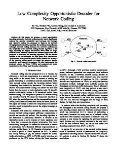
Fig. 1. The K × N × K channel model with interfering relays where K=3 and N = 10.
relays required to guarantee our achievability result. Numerical evaluation also indicates that the OND scheme has higher sumrates than those of the other relaying methods under realistic network conditions (e.g., finite N and SNR) since inter-relay interference is significantly reduced owing to the opportunistic gain. Note that unlike the case of [11], our protocol basically operates with local channel state information (CSI) at the transmitter and thus is suitable for distributed/decentralized networks. The rest of this paper is organized as follows. In Section II, we describe the system and channel models. In Section III, the proposed OND protocol with alternate relaying is specified and its achievable DoF is analyzed. Numerical results of the OND scheme are provided in Section IV. Finally, we summarize the paper with some concluding remarks in Section V. We refer to our full paper [19] for more detailed description and all the proof. II. S YSTEM AND C HANNEL M ODELS Consider the K × N × K channel model with interfering relays to describe practical multiuser relaying networks for the case where each S–D pair is geographically far apart, thus creating a huge challenge for spectral efficiency. As illustrated in Fig. 1, there are K S–D pairs, where each receiver is the destination of exactly one source node and is interested only in traffic demands of the source. As in the typical cooperative relaying setup, N relay nodes are located in the path between S–D pairs so as to help to reduce path-loss attenuations. Each source transmits its own message to the corresponding destination only through one of N relays, and thus it is assumed that there is no direct path between an S–D pair. The example for K = 3 and N = 10 is shown in Fig. 1. Suppose that each node is equipped with a single transmit antenna. Each relay node is assumed to operate in half-duplex mode and to fully decode, re-encode, and retransmit the source message i.e., decode-and-forward protocol is taken into account. Unlike the work in [8], [10], N relays are assumed to interfere with each other.2 With alternate relaying, each selected relay node toggles between the transmit and listen modes for alternate 2 If
we can cancel the interfering signals among multiple relays, then the existing achievable scheme of the K × N × K channel can also be applied here.
2672
time slots of message transmission of the sources. If N is sufficiently large, then it is possible to exploit the channel randomness for each hop and thus to obtain the opportunistic gain in multiuser environments. We assume that each node (either a source or a relay) has an average transmit power constraint P . Now, let us turn to channel modeling. Let Sk , Dk , and Ri denote the kth source, the corresponding destination, and the ith relay node, respectively, where k ∈ {1, · · · , K} and (1) (2) i ∈ {1, · · · , N }. The terms hik , hki ∈ C denote the channel coefficients from Sk to Ri and from Ri to Dk , corresponding (r) to the first and second hops, respectively. The term hin ∈ C indicates the channel coefficient between two relays Ri and Rn . All the channels are assumed to be Rayleigh, having zeromean and unit variance, and to be independent across different i, k, n, and hop index. We assume a block-fading model, i.e., the channels are constant during one block (e.g., frame), consisting of one scheduling time slot and L data transmission time slots, and changes to a new independent value for every block. III. ACHIEVABILITY R ESULT In this section, we propose the OND protocol in the K × N × K channel with interfering relays. Then, its performance is analyzed in terms of achievable DoF. A. Opportunistic Network Decoupling in the K × N × K Channel With Interfering Relays In this subsection, we introduce an OND protocol as the achievable scheme to guarantee the optimal DoF of the K × N × K channel with inter-relay interference, where 2K relay nodes among N candidates are opportunistically selected for data forwarding in the sense of having a sufficiently small amount of interference level. The proposed scheme is basically performed by utilizing the channel reciprocity of TDD systems. Suppose that π1 (k) and π2 (k) denote the indices of two relays communicating with the kth S–D pair for k ∈ {1, · · · , K}. In this case, without loss of generality, assuming that L is an odd number, the specific steps of each node during one block are described as follows: • Time slot 1: Sources S1 , · · · , SK transmit their first (1) (1) (1) encoded symbols x1 (1), · · · , xK (1), where xk (l) represents the lth transmitted symbol of the kth source node.3 A set of K selected relay nodes, Π1 = {π1 (1), · · · , π1 (K)}, operating in receive mode at each (1) (1) odd time slot, listens to x1 (1), · · · , xK (1) (note that a relay selection strategy will be specified in a later section). Other N − K relay nodes and destinations D1 , · · · , DK remain idle. • Time slot 2: The K sources transmit their en(1) (1) coded symbols x1 (2), · · · , xK (2). The K relays in 3 For notational convenience, we use scalar notation instead of vector notation for each coding block from source nodes, but the size of each symbol is assumed to be sufficiently long to achieve Shannon-theoretic channel capacity.
IEEE ICC 2014 - Mobile and Wireless Networking Symposium
Fig. 2.
The overall procedure of our OND scheme with alternate relaying in the K × N × K channel with interfering relays.
the set Π1 forward their first re-encoded symbols (2) (2) xπ1 (1) (1), · · · , xπ1 (K) (1) to the corresponding K destinations. If the relays in Π1 successfully decode the (2) corresponding symbols, then xπ1 (k) (1) is the same as (1)
xk (1). Another set of K selected relay nodes, Π2 = {π2 (1), · · · , π2 (K)}, operating in receive mode at each (1) (1) even time slot, listens to and decodes x1 (2), · · · , xK (2) while being interfered with by Rπ1 (1) , · · · , Rπ1 (K) . The K destinations receive from Rπ1 (1) , · · · , Rπ1 (K) and (2) (2) decode xπ1 (1) (1), · · · , xπ1 (K) (1). The remaining N −2K relays keep idle. • Time slot 3: The K sources transmit their encoded (1) (1) symbols x1 (3), · · · , xK (3). The K relays π2 (1), · · · , π2 (K) forward their re-encoded symbols (2) (2) xπ2 (1) (2), · · · , xπ2 (K) (2) to the corresponding K destinations. Another K relays in Π1 receive and (2) (2) decode x1 (3), · · · , xK (3) while being interfered with by Rπ2 (1) , · · · , Rπ2 (K) . The K destinations receive from Rπ2 (1) , · · · , Rπ2 (K) and decode (2) (2) xπ2 (1) (2), · · · , xπ2 (K) (2). The remaining N − 2K relays keep idle. • The processes in time slots 2 and 3 are repeated to the (L − 1)th time slot. • Time slot L: The K relays in Π2 forward their re(2) (2) encoded symbols xπ2 (1) (L − 1), · · · , xπ2 (K) (L − 1) to the corresponding K destinations. The K sources and the other N − K relays remain idle. At each odd time slot l (i.e., l = 1, 3, · · · , L), let us consider the received signal at each selected relay for the first hop and the received signal at each destination for the second hop, respectively. For the first hop (Phase 1), the received signal at Rπ1 (i) is given by (1)
yπ1 (i) (l) = +
K ∑
(1)
(1)
hπ1 (i)k xk (l) +
k=1 (1) zπ1 (i) (l),
K ∑
(r)
(2)
hπ1 (i)π2 (n) xπ2 (n) (l − 1)
n=1
(1)
(2)
where xk (l) and xπ2 (n) (l − 1) are the lth and the (l − 1)th transmit symbol of Sk and transmit symbol of Rπ2 (n) , respectively. As addressed earlier, if relay Rπ2 (k) successfully (2) decode the received symbol, then it follows that xπ2 (k) (l − (1)
(1)
1) = xk (l − 1). The received signal yπ1 (i) (l) at Rπ1 (i) is corrupted by the independent and identically distributed (i.i.d.) and circularly symmetric complex additive Gaussian (1) noise zπ1 (i) (l) having zero-mean and variance N0 . Note that the second term in the right-hand side (RHS) of (1) indicates inter-relay interference, which occurs when the K relays in the set Π1 , operating in receive mode, listen to the sources, the relays are interfered with by the other set Π2 , operating in transmit mode. Note that when l = 1, relays have no symbols to transmit, and the second term in the RHS of (1) becomes zero. Similarly when l = L, sources do not transmit symbols, and the first term in the RHS of (1) becomes zero. For the second hop (Phase 2), assuming that the K selected relay nodes transmit their data packets simultaneously, the received signal at Dk is given by (2)
yk (l) =
2673
(2)
(2)
(2)
hkπ2 (n) xπ2 (n) (l − 1) + zk (l),
n=1 (2) zk (l)
where is the i.i.d. Gaussian noise having zero-mean and variance N0 . We also note that when l = 1, there are no signals from relays. Likewise, at each even time slot (i.e., l = 2, 4, · · · , L − 1), the received signals at Rπ2 (i) and Dk (i.e., the first and second hops) are given by (1) yπ2 (i) (l)
= +
K ∑
(1) (1) hπ2 (i)k xk (l)
+
K ∑
(r)
(2)
hπ2 (i)π1 (n) xπ1 (n) (l − 1)
n=1
k=1 (1) zπ2 (i) (l)
and (2)
yk (l) = (1)
K ∑
K ∑ n=1
(2)
(2)
(2)
hkπ1 (n) xπ1 (n) (l − 1) + zk (l),
IEEE ICC 2014 - Mobile and Wireless Networking Symposium
respectively. The overall procedure of the aforementioned OND scheme with alternate half-duplex relaying is illustrated ˜ π (k),k and Lπ (k),k are specified later in Fig. 2 (two terms L 1 2 in the following relay selection steps). Now, let us describe how to choose two types of relay sets, Π1 and Π2 among N relay nodes, where N is sufficiently large (the minimum N required to guarantee the DoF optimality will be analyzed in Section III-B). 1) Step 1 (The First Relay Set Selection): Let us first focus on selecting the set Π1 = {π1 (1), · · · , π1 (K)}, operating in receive and transmit modes in odd and even time slots, respectively. For every scheduling period, it is possible for relay Ri (1) (2) to obtain all the channel coefficients hik and hki by using a pilot signaling sent from all of the source and destination nodes before data transmission, where i ∈ {1, · · · , N } and k ∈ {1, · · · , K} (note that this is our local CSI assumption). When Ri is assumed to serve the kth S–D pair (Sk , Dk ), it then examines both i) how much interference is received from the other sources and ii) how much interference is generated by itself to the other destinations, by computing the following ˜ i,k : scheduling metric L ˜ i,k = L
K ∑
( ) (1) 2 (2) 2 him + hmi ,
(2)
˜ ˆ, · · · , L ˜ ˆ ˜ ˆ ˜ ˆ } are dismetrics {L ˆ , Lπ1 (k)+1, ˆ , · · · , LN,k 1,k π1 (k)−1,k k carded with respect to timer operation. If another relay has an opportunity to send the second RTS message in order to declare its presence, then it is selected to communicate with the corresponding S–D pair. When such K RTS messages are sent out in consecutive order, i.e., the set of K relays, Π1 = {Rπ1 (1) , · · · , Rπ1 (K) } is chosen, the timer-based algorithm for the first relay set selection terminates, yielding no RTS collision with high probability. 2) Step 2 (The Second Relay Set Selection): Now let us turn to choosing the set of K relay nodes (among N − K candidates), Π2 = {π2 (1), · · · , π2 (K)}, operating in receive and transmit modes in even and odd time slots, respectively. Using K RTS messages broadcasted from the K relay nodes in the set Π1 , it is possible for relay node Ri ∈ {1, · · · , N }\Π1 to compute the sum of inter-relay interference power generated ∑K (r) 2 from the relays in Π1 , denoted by k=1 hiπ1 (k) . When Ri is again assumed to serve the kth S–D pair (Sk , Dk ), it examines how much interference is received from the undesired sources and the selected relays in the set {1, · · · , N } \ Π1 for the first hop and how much interference is generated by itself to the other destinations by computing the following metric Li,k , termed total interference level (TIL):
m=1,m̸=k
where i ∈ {1, . . . , N } and k ∈ {1, . . . , K}. Note that the first ∑K (1) 2 term m=1,m̸=k him in (2) denotes the sum of interference power received at Ri for the first hop (i.e., 1). On the Phase ∑K (2) 2 other hand, the second term m=1,m̸=k hmi indicates the sum of interference power generating at Ri , which can be interpreted as the leakage of interference to the K −1 receivers expect for the corresponding destination, for the second hop (i.e., Phase 2) under the same assumption. ˜ i,k in (2), a timerAccording to the computed metrics L based method is used for relay selection similarly as in [20]. Note that the method based on time is considerably suitable in distributed systems in the sense that information exchange among all relay nodes can be minimized. At the beginning of every scheduling period, the relay Ri computes the set ˜ i,1 , · · · , L ˜ i,K }, and then starts of K scheduling metrics, {L its own timer with K initial values, which are proportional to the K metrics. Thus, there exist N K metrics over the whole relay nodes, and we need to compare them so as to determine who will be selected. The timer of the relay Rπ1 (k) ˆ ˜ ˆ ˆ among N K metrics will expire with the least one L π1 (k),k ˆ ∈ {1, · · · , N } and kˆ ∈ {1, · · · , K}. The first, where π1 (k) relay then transmits a short duration RTS (Request to Send) message, signaling its presence, to the other N − 1 relays. Thereafter, the relay Rπ1 (k) ˆ is first selected to forward the ˆ S–D pair’s packet. All the other relays are in listen mode kth while waiting for their timer to be set to zero (i.e., to expire). At the stage of deciding who will send the second RTS message, it is assumed that the other relays are not allowed to ˆ S–D pair, and thus the associated communicate with the kth
2674
˜ i,k + Li,k = L
K ∑ (r) 2 hiπ1 (k) k=1
=
K ∑ m=1,m̸=k
( K ) ∑ (1) 2 (2) 2 (r) 2 him + hmi + hiπ1 (k) , (3) k=1
where i ∈ {1, . . . , N } and k ∈ {1, . . . , K}. According to the computed TIL Li,k , we also apply the timer-based method used in Step 1 for the second relay set selection. The relay Ri ∈ {1, · · · , N } \ Π1 computes the set of K TILs, {Li,1 , · · · , Li,K }, and then starts its timer with K initial values, proportional to the K TILs. Thus, we need to compare (N −K)K TIL metrics over the relay nodes in the set {1, · · · , N } \ Π1 in order to determine who will be selected as the second relay set. The rest of the relay set selection protocol (i.e., RTS message exchange among relay nodes) almost follows the same line as that of Step 1. The timerbased algorithm for the second relay set selection terminates when K RTS messages are sent out in consecutive order. Then, K relay nodes having a sufficiently small amount of TIL Li,k are selected as the second relay set Π2 . We remark that owing to the channel reciprocity of TDD systems, the sum of inter-relay interference power received ∑K (r) 2 at any relay Ri ∈ Π1 , k=1 hiπ2 (k) , also turns out to be sufficiently small when N is large. That is, it is also guaranteed that K selected relays in the set Π1 have a sufficiently small amount of TIL. 3) Step 3 (Data Transmission): The 2K selected relays request data transmission to their desired source nodes. Each source (Sk ) then starts to transmit data to the corresponding destination (Dk ) via one of its two relay nodes alternately
IEEE ICC 2014 - Mobile and Wireless Networking Symposium
10
Total Interference Level (TIL)
(Rπ1 (k) or Rπ2 (k) ), which was specified earlier. If the TILs of the selected relays are arbitrarily small, then i) the associated undesired source–relay and relay–destination channel links and ii) the inter-relay channel links are all in deep fade. In Section III-B, we will show that it is possible to choose such relays with the help of the multiuser diversity gain. At the receiver side, each relay or destination detects the signal sent from its desired transmitter, while simply treating interference as Gaussian noise. Thus, no multiuser detection is performed at each receiver, thereby resulting in easier implementation.
2
Random Selection Max-Min SNR Proposed OND
10
1
0
10 1 10
10
B. Achievable DoF In this subsection, using the scaling argument bridging between the number of relays, N , and the received SNR (refer to [7], [21], [22] for the details), we shall show 1) the achievable DoF of the K × N × K channel with interfering relays as N increases and 2) the minimum N required to guarantee the achievability result. The total number of DoF, denoted by DoFtotal , is defined as [1] ) K ( ∑ Tk (SNR) DoFtotal = lim , SNR→∞ log2 SNR k=1
where Tk (SNR) denotes the transmission rate of source Sk . The following theorem establishes our main result. Theorem 1: Suppose that the OND scheme with alternate relaying is used for the K × N × K channel with interfering relays. Then, for L data transmission time slots, (L − 1)K L ( ) 3K−2 4 is achievable if N = ω SNR . Note that the achievable DoF asymptotically approaches K for large L. From Theorem 1, let us provide the following interesting discussions regarding the DoF achievability. Remark 1: The proposed OND scheme with alternate relaying achieves K DoF in the K ×N ×K channel with interfering links among relay nodes, if the number of relay nodes, N scales faster than SNR3K−2 and the number of transmission symbols in one block, L, is sufficiently large. The parameter N required to obtain full DoF (i.e., K DoF) exponentially increase with the number of S–D pairs, K, in order to make the sum of 3K − 2 interference terms in the TIL metric nonincreasing with increasing SNR at each relay, which enables that all the interfering signals are nulled out at each selected relay by exploiting the multiuser diversity gain. Remark 2: It is not difficult to show that the centralized relay selection method that maximizes the received SINR (at either the relay or the destination) using global CSI at the transmitter, which is a combinatorial problem with exponential complexity, gives the same relay scaling result ( ) N = ω SNR3K−2 along with full DoF. However, even with our OND scheme using decentralized relay selection based DoFtotal ≥
4 f (x)
2
N
= ω(g(x)) means that limx→∞
g(x) f (x)
= 0.
2675
Fig. 3.
The TIL versus N when K = 3.
only on local CSI, the same achievability result is obtained, thus resulting in much easier implementation. In addition, a simple upper bound on the DoF is shown and compared to the achievable DoF in the following argument. Remark 3: Using the min-cut upper bound, it is obvious to show that the number of DoF for the MIMO channel, generated by the cut such that K transmit nodes are on the left of the network and the other nodes including active relays and destination nodes are on the right, is upper-bounded by K. Hence, it turns out that even with the half-duplex relaying assumption, our achievable scheme is DoF-optimal with the help of the alternate relaying. Note that this upper bound is generally derived regardless of whether the number of relays, N , tends( to infinity) or not, whereas the scaling condition N = ω SNR3K−2 is necessary in the achievability proof of the OND scheme. IV. N UMERICAL E VALUATION In this section, we perform computer simulations to validate the performance of the proposed OND scheme for finite parameters N and SNR. For comparison, two baseline relay selection schemes operating based on local CSI in a distributed manner are also considered: 1) a random relay selection scheme and 2) a Max-Min SNR scheme, which selects the S– D pair such that from relay Ri ’s perspective (i ∈ {1, · · · , N }), the minimum out of the channel gains of two communication links (either from Sk to Ri or from Ri to Dk ) becomes the maximum among the associated minimum gains of K S– D pairs. The Max-Min scheme is well-suited for relay-aided systems if interfering links are absent. Alternate relaying is also used for each of the two compared schemes. The average amount of TIL in (3) is first evaluated as the number of relays, N , increases. In Fig. 3, the log-log plot of TIL versus N is shown when K = 3.5 Our result indicates that the TIL of the OND scheme tends to decrease almost linearly with N (which is verified analytically in [19]) while the TIL of the other two schemes is not reduced according to 5 Even if it seems unrealistic to have a great number of relays in cooperative relay networks, the range for parameter N is taken into account to precisely see some trends of curves varying with N .
IEEE ICC 2014 - Mobile and Wireless Networking Symposium
1 0.9
Sum-Rate (bits/s/Hz)
0.8
Random Selection Max-Min SNR Proposed OND
0.7 0.6 0.5 0.4 0.3 0.2 0.1 0 1 10
10
2
N
Fig. 4. 10dB.
The sum-rates versus N when K = 3, SNR = 30dB, and INRR =
increasing N . It is further seen how many relays are required with the OND scheme to guarantee that the TIL is less than a small constant for a given parameter K. In addition, Fig. 4 illustrates the achievable sum-rates versus N when K = 3, SNR = 30dB, and INRR = 10dB, where INRR denotes the inter-relay interference-to-noise ratio (INR). For the max-min SNR scheme, the desired channel gain grows as N increases while the amount of interference remains the same. In consequence, it is examined that the rate of increase in the sum-rates of the OND scheme with respect to N is much higher than that of the max-min SNR scheme owing to the significant interference suppression. V. C ONCLUSION An efficient distributed OND protocol was proposed for the K × N × K channel with interfering relays, referred to as one of multi-source interfering relay networks. A novel relay scheduling strategy with alternate half-duplex relaying was presented in two-hop environments, where a subset of relays is opportunistically selected in terms of producing the minimum total interference level, thereby resulting in network decoupling. It was shown that the OND protocol asymptotically achieves full DoF even in the presence of inter-relay interference and half-duplex assumption, provided that the number of relays, N , scales faster than SNR3K−2 . Numerical evaluation was also shown to verify that our scheme outperforms the other relay selection methods under realistic network conditions (e.g., finite N and SNR) with respect to sum-rates. ACKNOWLEDGEMENT This research was funded by the MSIP(Ministry of Science, ICT & Future Planning), Korea in the ICT R&D Program 2013. R EFERENCES [1] V. R. Cadambe and S. A. Jafar, “Interference alignment and degrees of freedom of the K-user interference channel,” IEEE Trans. Inf. Theory, vol. 54, no. 8, pp. 3425–3441, Aug. 2008. [2] T. Gou and S. A. Jafar, “Degrees of freedom of the K-user M × N MIMO interference channel,” IEEE Trans. Inf. Theory, vol. 56, no. 12, pp. 6040–6057, Dec. 2010.
2676
[3] F. Sun and E. de Carvalho, “A Leakage-based MMSE beamforming design for a MIMO interference channel,” IEEE Sig. Process. Lett., vol. 19, no. 6, pp. 368–371, June 2012. [4] S. A. Jafar and S. Shamai (Shitz), “Degrees of freedom region of the MIMO X channel,” IEEE Trans. Inf. Theory, vol. 54, no. 1, pp. 151– 170, Jan. 2008. [5] C. Suh and D. Tse, “Interference alignment for celluar networks,” in Proc. 46th Annual Allerton Conf. Commun., Control, and Computing, Monticello, IL, Sep. 2008. [6] A. S. Motahari, O. Gharan, M.-A. Maddah-Ali, and A. K. Khandani, “Real interference alignment: Exploiting the potential of single antenna systems,” IEEE Trans. Inf. Theory, submitted for publication, [Online]. Available: http://arxiv.org/abs/0908.2282. [7] B. C. Jung, D. Park and W.-Y. Shin, “Opportunistic interference mitigation achieves optimal degrees-of-freedom in wireless multi-cell uplink networks,” IEEE Trans. Commun., vol. 60, no. 7, pp. 1935–1944, Jul. 2012. [8] T. Gou, S. A. Jafar, C. Wang, S.-W. Jeon, S.-Y. Chung, “Aligned interference neutralization and the degrees of freedom of the 2 × 2 × 2 interference channel,” IEEE Trans. Inf. Theory, vol. 58, no. 7, pp. 4381– 4395, Jul. 2012. [9] B. Rankov and A. Wittneben, “Spectral efficient protocols for half-duplex fading relay channels,” IEEE J. Select. Areas Commun., vol. 25, no. 2, pp. 379–389, Feb. 2007. [10] I. Shomorony and A. S. Avestimehr, “Degrees of freedom of two-hop wireless networks: “Everyone gets the entire cake”,” in Proc. 50th Annual Allerton Conf. Commun., Control, and Computing, Monticello, IL, Oct. 2012. [11] T. Gou, C. Wang, and S. A. Jafar, “Aligned interference neutralization and the degrees of freedom of the 2 × 2 × 2 interference channel with interfering relays,” in Proc. 49th Annual Allerton Conf. Commun., Control, and Computing, Monticello, IL, Sep. 2011. [12] T. Gou, C. Wang, and S. A. Jafar, “Degrees of freedom of a class of non-layered two unicast wireless networks,” in Proc. 45th Asilomar Conf. Signals, Systems and Computers, Pacific Grove, CA, Nov. 2011. [13] F. Sun, T. M. Kim, A. J. Paulraj, E. de Carvalho, and P. Popovski, “Celledge multi-user relaying with overhearing,” IEEE Commun. Lett., vol. 17, no. 6, pp. 1160–1163, Jun. 2013. [14] R. Knopp and P. Humblet, “Information capacity and power control in single cell multiuser communications,” in Proc. IEEE Int. Conf. Commun. (ICC), Seattle, WA, Jun. 1995, pp. 331–335. [15] P. Viswanath, D. N. C. Tse, and R. Laroia, “Opportunistic beamforming using dumb antennas,” IEEE Trans. Inf. Theory, vol. 48, no. 6, pp. 1277–1294, Aug. 2002. [16] M. Sharif and B. Hassibi, “On the capacity of MIMO broadcast channels with partial side information,” IEEE Trans. Inf. Theory, vol. 51, no. 2, pp. 506–522, Feb. 2005. [17] W.-Y. Shin, S.-Y. Chung, and Y. H. Lee, “Parallel opportunistic routing in wireless networks,” IEEE Trans. Inf. Theory, vol. 59, no. 10, pp. 6290–6300, Oct. 2013. [18] F. Xue and S. Sandhu, “Cooperation in a half-duplex Gaussian diamond relay channel,” IEEE Trans. Inf. Theory, vol. 53, no. 10, pp. 3806–3814, Oct. 2007. [19] W.-Y. Shin, H. J. Yang, and B. C. Jung, “Opportunistic network decoupling,” in preparation. [20] A. Bletsas, A. Khisti, D. P. Reed, and A. Lippman, “A simple cooperative diversity method based on network path selection,” IEEE J. Select. Areas Commun., vol. 24, no. 3, pp. 659–672, Mar. 2006. [21] H. J. Yang, W.-Y. Shin, B. C. Jung, and A. Paulraj, “Opportunistic interference alignment for MIMO interfering multiple-access channels,” IEEE Trans. Wireless Commun., vol. 12, no. 5, pp. 2180–2192, May 2013. [22] H. J. Yang, B. C. Jung, W.-Y. Shin, and A. Paulraj, “Codebookbased opportunistic interference alignment,” IEEE Trans. Sig. Process., under review for possible publication, [Online]. Available: http://arxiv.org/abs/1310.2028.