Perceiving Ribs in Single-View Wireframe Sketches of Polyhedral Shapes P. Company1, P.A.C. Varley1, R. Plumed2, and R. Martin3 1
2
Institute of New Imaging Technology, Universitat Jaume I, Spain Department of Mechanical Engineering and Construction, Universitat Jaume I, Spain 3 School of Computer Science & Informatics, Cardiff University, UK
Abstract. As part of a strategy for creating 3D models of engineering objects from sketched input, we attempt to identify design features, geometrical structures within objects with a functional meaning. Our input is a 2D B-Rep derived from a single view sketch of a polyhedral shape. In this paper, we show how to use suitable cues to identify algorithmically two additive engineering design features, angular and linear ribs.
1
Introduction
Our aim is to find design features, geometrical structures within objects with a functional meaning. In a previous paper [1], we presented a catalogue of common design features, listing for each type of feature any known successful algorithms for detecting the implied presence of such features in sketches. We noted that, as a result of previous interest in machining features, there are many known algorithms for detecting subtractive features or "intrusions", but far fewer algorithms for detecting additive features or "protrusions" [2, 3]. Our motivation in this paper is to fill this gap. We briefly review what is known about both human and artificial perception of features, and we then introduce a new approach aimed at finding one specific design feature, the rib, through indirect cues. We distinguish between angular ribs (or simply ribs) and linear ribs (or rails). The new contribution here is the search for perceptual cues linked to features embedded in the sketched shapes. Because of their function, ribs are theoretically important in computer-aided design as the ideal size of a rib for a particular size of part depends on strength calculations. Once a feature has been flagged as a rib, a CAD/CAE package should know that its dimensions are to be fixed not by geometric constraints but by the physical properties of the material. It is thus important to find and classify ribs to distinguish them from more "geometric" features. Our intended approach differs from other feature recognition performed on inaccurate models in that our input is a 2D graph-like line-drawing, derived from a single view sketch of a polyhedral shape. This introduces one intrinsic limitation: as sketches contain only pictorial information, depth information comes only from the interpretation of perceptual cues. The second limitation, considering only polyhedral shapes, is a simplification that we hope we will relax in the future. G. Bebis et al. (Eds.): ISVC 2012, Part II, LNCS 7432, pp. 557–567, 2012. © Springer-Verlag Berlin Heidelberg 2012
558
P. Company et al.
Our goal is to understand the function of an object from a 2D sketch. Finding features is an important step in this process, but it is not the whole story. We envisage a subsequent step in which, given the possible presence of various features, some form of statistical processing is used to combine compatible features and reject contradictory features (although at present we leave open the problem of which particular statistical methodology is to be used for this). Thus, the feature detection algorithms we present here return a statistical likelihood: they do not answer the question “is this a rib?” but the question “how likely is this to be a rib?” Section 2 describes the current state of the art of perception of design features. Section 3 presents an algorithm for finding ribs and dividers, and Section 4 presents an algorithm for finding rails and slots. Section 5 presents some test results, and Section 6 presents our conclusions.
2
State of the Art in Perception of Features
Although the “rule of concave creases” explains quite well how human perception cuts objects into fragments, and its most famous formulation [4] has been used with reasonable success in areas such as segmentation of 3D meshes [5], it is not enough by itself to produce an algorithmic equivalent for artificial perception of objects from 2D sketches or line drawings. Artificial perception of fragments of a scene dates back to the “block-world” introduced by Guzman [6]. Early approaches to breaking down objects to perceive their fragments as elements of a CSG tree were proposed by Bergengruen [7] and Wang and Grinstein [8], among others. A survey of contributions to geometrical sketch reconstruction up to 2005 [9] shows that approaches producing CSG output used multiple view input and were less common than those producing B-Rep output. It is noteworthy that nearly all contributions were concerned with geometry and shape, not with functionality. Most sketch based modelling (SBM) systems which provide CSG output use multiple view input, and drive the decomposition by geometric considerations (finding basic geometrical shapes such as prisms and wedges), not design features [10]. Since then, the emphasis has started to change. The most useful recent contributions, by Wen et al. [11] and Rivers et al. [12], deal with multiple view input and are interactive. An interesting aspect of the work by Wen et al. [11] is that they identify features, by searching in multiple view drawings for what they call "semantic information". Another field, automatic feature recognition (AFR), has evolved in parallel. A recent survey of this field can be found in [2]. Two main branches exist. The first, useless for SBM, is the input of a CSG model containing CAD features which must be converted to Computer-Aided Manufacturing (CAM) features. But the second branch is aimed at the closer goal of finding CAM features in B-Rep 3D models. AFR methods follow three main approaches: graph-based, volumetric decomposition and hint-based. Hint based AFR (where an AFR “hint” is effectively the same thing as a “clue” or “cue” in human perception and SBM) was introduced by Vandenbrande and
Perceiving Ribs in Single-View Wireframe Sketches of Polyhedral Shapes
559
Requicha [13], and extended by Han and Requicha [14]. Note, however, that input for AFR is 3D: its goal is to algorithmically extract manufacturing features from CAD 3D models. Since the goal of SBM is producing 3D models from sketches, while the goal of AFR is finding features in 3D models, a strategy of reconstructing first and then finding features looks obvious. However, this coupling has not yet proved successful, and the problem is still open. Here, we consider the alternative strategy: first find features, then reconstruct. We hope that detecting features first may, for example, help us to constrain the reconstruction (e.g. knowing depth relationships in the feature may help to fix other depth relationships). In order to search for design features in sketches, we must replace AFR’s 3D input by 2D input, by suitably adapting the hints. Detecting features before reconstruction was first applied for single-view sketchbased modelling purposes by Varley [15]. His input was natural single-view linedrawings. He looked for underslots and valleys by trying to match the region around each T-junction in the drawing with some templates. If a match was found, it was given a certain figure of merit. Such template matching remains the best choice for finding features in natural drawings, when no further information is available. As far as we know, hint-based AFR strategies have never been applied to singleview 2D wireframes. Our hypothesis is that, since more information is available in wireframes (with hidden lines drawn), particularly after faces have been found, than in natural drawings (without hidden lines and faces), AFR strategies could be adapted to 2D input to find features in wireframes.
3
Finding Ribs and Dividers in Single-View Wireframes
Mechanical engineers have no difficulty in detecting ribs embedded in objects: they can imagine how the object will work to resist the loads it is designed for. They can thus decide whether a fragment is there simply to reinforce the whole object without significantly increasing its weight. However, detecting such functionality is a complex ability, hard to replicate, not only for machines but even for novice engineering students. Fortunately, some peculiarities of its shape are easy to detect. The most individual geometrical aspect of ribs is that they are thin walls. The cue linked to a thin wall is that the border faces are narrow and rectangular. We note that a rectangle in 3D usually appears as a parallelogram in an axonometric 2D image, so a parallelogram in 2D is an indirect cue of a rectangle in 3D. As it is joined to the whole object, most of a rib's border faces are embedded in the object (border faces of webs are fully embedded). However, usually one border face of a rib is not embedded, so the first task when detecting ribs is to look for thin border faces, quadrilateral faces with two quite short opposed edges and two longer edges. Secondly, as ribs are “walls”, they are extruded shapes. The border face should be a parallelogram, and the two faces connected to the longer edges of the border face should be equal. If the input drawing is a wireframe, both faces are known, so this condition helps to disambiguate candidate ribs.
560
P. Company et al.
Third, as the rib "interrupts" the faces where it is embedded (at least if objects are polyhedral), edges connected to the vertices of the rib's lateral faces but which do not belong to the rib (we call them "external edges") should be collinear with the corresponding external edges on the opposite side of the rib. This collinearity of external edges is not considered as a requisite, but is an indirect cue which reinforces the assumption than the fragment is a rib. Hence, if this condition is met, the figure of merit which measures the likeliness that a candidate rib should be considered as an actual rib should be increased. Finally, since the algorithm detects thin walls, and dividers are also thin walls, the algorithm also detects dividers. We must distinguish ribs from dividers, since dividers are purely geometric: they partition space into separate regions or limit movement with respect to another part. (However, multiple dividers may also represent cooling fins, making them another example of design features whose measurements must be derived from physical modelling and not merely from geometric constraints.) Hence, dividers are likely to have more than one border face, and their lateral faces are likely to be quadrilateral. These differences are used in the algorithm to discriminate between ribs and dividers: ribs with multiple border faces are re-labelled as dividers. Parallelogram lateral faces increase the likelihood of the feature being a divider, and decrease that of it being a rib. The procedure for finding ribs requires 2D B-Reps. Although further improvements are still required, conversion from wireframe sketches into 2D linedrawings is a well known stage in SBM (readers should look for “recognition” in [16]), but conversion from natural into wireframe line-drawings is not so easy [15], [17]. Faces must also have been detected in advance (the process of finding faces in 2D B-Reps of polyhedral objects has been explained elsewhere [18]). Hence, we assume a graph-like wireframe input containing a list of vertices, a list of edges and a list of faces. Vertices are defined by their x and y coordinates. Edges are defined by the two vertices they connect. Faces are defined as closed loops of edges. The proposed procedure for detection of ribs can then be summarised as follows: Algorithm 1: Pseudocode for the detection of ribs: 01: Begin Thin Wall detect 02: for each face f 03: if f is quadrilateral (i.e. a four sided face) 04: if f does not belong to any rib or divider and is SLENDER 05: Mark f as a border face 06: Mark faces connected to the long edges of f as lateral1 and 2 07: if lateral 1 and 2 are SIMILAR 08: return Thin-Wall (border, lateral1, lateral2) 09: end if 10: end if 11: end if 12: end for 13: return not-Thin-Wall 14: End Thin Wall detect
Perceiving Ribs in Single-View Wireframe Sketches of Polyhedral Shapes
01: 02: 03: 04: 05: 06: 07: 08: 09: 10: 11: 12:
Begin External Are Collinear flag_collinear ←true for each vertex v1 of the lateral face 1 Find the similar vertex v2 of lateral face 2 Find the one, and only one, external edge e1 of vertex v1 Find the one, and only one, external edge e2 of vertex v2 if e1 and e2 are not-collinear flag_collinear ←false end if end for return flag_collinear End External Are Collinear
01: 02: 03: 04: 05: 06: 07: 08: 09: 10: 11: 12: 13: 14: 15: 16: 17: 18: 19: 20: 21:
Begin Ribs detection do while (Thin Wall detect) if (lateral1 and lateral2 belong to a previous rib R) Add the new border to the previous rib R Re-label rib R as a divider else Define a new rib R (border, lateral1, lateral2) Assign an average figure of merit to the new rib R end if if External Are Collinear Increase the figure of merit of R end if if laterals are PARALLELOGRAMS if R is divider Increase the figure of merit of the divider R else Decrease the figure of merit of the rib R end if end if end while End Ribs detection
561
The terms in capitals in the pseudocode are functions not listed in the pseudocode, and are explained here. A face is considered slender if it is quadrilateral, contains two opposite short edges, and two opposite long edges. Two lateral faces are considered similar if they achieve three conditions: the faces must have the same number of vertices, vertices can be paired in pairs whose distance is always equal, and the line segments defined by the paired vertices must be parallel. A face is a parallelogram if it is quadrilateral and both pairs of opposed edges (arbitrarily 0-2 and 1-3) have equal length and are parallel. The terms underlined in the pseudocode depend on tuning parameters. Comparisons for short, long, equal and parallel-collinear need thresholds, to deal with imperfections inherent in the sketching process.
562
4
P. Company et al.
Finding Rails and Slots in Single-View Wireframes
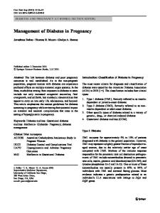
Some linear ribs are present to provide structural reinforcement, but other linear ribs act in pairs with slots in other parts, and their function is to produce sliding joints between adjacent parts in an assembly (Figure 1 left). We call these rails. The shape of rails is the complement of the slots in the paired part. Hence, the procedure for finding rails is similar to that for finding slots.
Fig. 1. Rail and slot (left), and some of their 2D cues (right)
Firstly, slots are long and narrow holes machined in flat surfaces. A machined slot produces a result resembling an incomplete prism, where the border/bottom face and the lateral faces of the slot are all quadrilateral (Figure 1 right). Secondly, lateral faces should have the same shape. Thirdly, as the rail/slot interrupts the faces in which it is embedded, the figure of merit which measures the likeliness of candidate rails should be increased if external edges of lateral faces are collinear. Since most common rails and slots are wider than deeper, the figure of merit is increased if laterals are slender (quadrilateral and narrow). The proposed procedure can be summarised as follows: Algorithm 2: Pseudocode for the detection of slots and rails: 01: Begin Candidate-Rail detect 02: for each face f 03: if f is SEMIPARALLELOGRAM and does not belong to another rail 04: Mark f as a border/bottom face 05: Mark faces connected to the opposed long edges of f as lateral1 and 2 06: if lateral 1 and 2 are SEMIPARALLELOGRAM 07: if lateral 1 and 2 are SIMILAR 08: return Candidate Rail (border, lateral1, lateral2) 09: end if 10: end if 11: Mark faces connected to the opposed short edges of f as lateral1 and 2 12: if lateral 1 and 2 are SEMIPARALLELOGRAM 13: if lateral 1 and 2 are SIMILAR 14: return Candidate Rail (border, lateral1, lateral2) 15: end if 16: end if 17: end if 18: end for
Perceiving Ribs in Single-View Wireframe Sketches of Polyhedral Shapes
19: 20:
return no-Candidate-Rail End Candidate-Rail detect
01: 02: 03: 04: 05: 06: 07: 08: 09: 10: 11: 12:
Begin Rails detection do while (Candidate Rail detect) if (lateral1 and lateral2 belong to a previous rail R) Add the new border to the previous rail R Re-label rail R as a blind rail else Define a new rail R (border, lateral1, lateral2) Assign an average figure of merit to the rail R if External Are Collinear Increase the figure of merit of R end if if laterals are SLENDER and share their long sides with the border/bottom face Increase the figure of merit of R end if end if end while End Rails detection
13: 14: 15: 16: 17:
563
A comparison of the rail pseudocode with the rib pseudocode shows the similarities and differences between them. For instance, in the rail pseudocode the border/bottom need only be a semiparallelogram (there is no need for it to be slender). However, the figure of merit increases if laterals are slender. The function semiparallelogram returns true if faces are quadrilateral and their long opposed sides are parallel to each other. This is used instead of parallelogram, since non-parallel short edges are quite common for slots which start or end in inclined faces (Figure 3 centre, Figure 4 centre).
5
Results
After several tests, we tuned the ribs algorithm to the following thresholds: (T1) lines shorter than 20% of the minimum side of the bounding box of the sketch are considered short; (T2) lines more than twice as long as the longer of the two short sides of each quadrilateral (long>2*max(short1, short2)) are considered long for this quadrilateral; (T3) lines are collinear if their orientation differs by less than 9º. The thresholds for similar faces are: (T4) vertices may be paired whose distances differ by less than 20%, and (T5) orientations of segments joined by paired vertices must differ by less than 15º. Both deviations are measured from their respective median values. The initial average figure of merit is 0.51 (T6). If external edges are collinear, the figure of merit increases by 10% (T7) in all cases. If lateral faces are parallelograms, the figure of merit increases by 25% (T8) for candidate dividers and decreases by 40% (T9) for candidate ribs. If lateral faces are slender, the figure of merit for rails
564
P. Company et al.
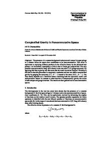
and slots increases by 25% (T10). Candidate features with a figure of merit equal or higher than average are considered true features. Tuned in this way, the algorithm succeeds in identifying ribs in our sketches. Parameters T1 and T2 are used to detect border faces, encoding geometrical differences linked to design intent. Changing these thresholds would result in "fat" ribs being accepted, or "thin" ribs being rejected (as far as we know, the limiting thickness for a rib to be still considered as a rib has never been fixed). Parameters T3, T4 and T5 allow for the imperfections inherent in freehand sketches. Their effect is illustrated in figures 5 and 6. Parameter T6 is set to 50% plus a small margin to defend against round-offs. Parameter T9 must be greater than T7, to prevent walls with parallelogram lateral faces from being accepted as better than average ribs. Our results are highly insensitive to changes in parameters T6 to T10. Figure 2 illustrates how some of the original strokes (left) are first vectorised into wireframes, whose vertices are merged to get graph-like drawings. Then the algorithm detects the ribs and dividers (right).
Fig. 2. Four examples where sketches containing ribs or dividers (left), are vectorised into their corresponding line-drawings with the features highlighted (right)
We obtained similar results for rails and slots (Figure 3). Sequential execution of both algorithms generally gives good results too, as shown in Figure 4 left.
Fig. 3. Sketches containing rails or slots
Perceiving Ribs in Single-View Wireframe Sketches of Polyhedral Shapes
565
The hollow rib in the example in Figure 4 centre illustrates a major problem: since the input is a 2D B-Rep, the current algorithm does not distinguish between true ribs and “negative ribs”. A possible solution would be labelling the graph-like linedrawing, since labelling edges as convex and concave helps to detect hollow ribs [19, 20]. Before running line labelling, 2D hidden edges detection must be used [21], since line labelling only makes sense for natural drawings. Finally, ribs at the ends of objects are not yet detectable (Figure 4 right). A possible solution for this case would be detecting whether one of the lateral faces is a "border" face, i.e. a face containing one or more border edges, and accepting such faces as candidate lateral faces (with a figure of merit increasing with the increasing number of border edges). In this case, instruction 7 of the algorithm 1 should be modified as: if (lateral 1 and 2 are SIMILAR) or (lateral 1 or lateral 2 is border).
Fig. 4. Sequential detection of ribs and rails (left and centre), and corner ribs (right)
During our tests, false negatives only happened for poor quality sketches (such as the corner highlighted in Figure 5 left) which resulted in distorted graphs. Relaxing tuning parameters would reduce false negatives, but would also produce some false positives.
Fig. 5. Poor quality scribbled corner results in a rail difficult to detect
The alternative of tidying up the sketch before detecting features has proved useful to some extent. We used a modified version of the batch beautification described in [22], which is adequate when distortions are local and not too strong (as around the highlighted vertex in Figure 5), but is insufficient for high distortions (such as those in Figure 6).
566
P. Company et al.
However, such tidying should not be necessary: our approach is robust, in that, as was said in the introduction, the question we aim to answer is “how likely is this to be a rib?” Hence, we believe that we shall be able to relax the acceptance criteria in order to detect such dubious representations as "weak" features with a low figure of merit. In the end, we want our algorithm to detect what humans can perceive, and we want our algorithm to doubt where humans doubt.
Fig. 6. Poor quality scribbled sketch and the unsuccessful attempt to tidy up
6
Conclusions and Future Work
Adapting hint-based AFR to 2D sketched input has been little considered before. In this work in progress, results show that, after adapting the approaches to 2D imperfect input and tuning the algorithms, they identify many common ribs, dividers, rails and slots from suitable indirect cues. Our goal is to understand the function of an object from a 2D sketch. Finding features is the first step. We envisage a subsequent step in which, given the possible presence of various features, some form of statistical processing is used to combine compatible features and reject contradictory features. Thus, the feature detection algorithms we present here return a statistical likelihood: they do not answer the question “is this a rib?” but the question “how likely is this to be a rib?” We hope then to be able to produce CSG feature trees from 2D sketches, by first converting the sketch into a 2D B-Rep, and then perceiving design features to explicitly recreate a mind's eye CSG tree embedded in sketches of engineering parts. Towards this end, when design features cannot be found directly in the sketch, indirect cues resulting from their presence should be sought instead. Acknowledgements. This work was partially funded by financial support from the Ramon y Cajal Scholarship Programme and by the "Pla de Promoció de la Investigació de la Universitat Jaume I", project P1 1B2010-01.
References 1. Plumed, R., Varley, P.A.C., Company, P.: Features and Design Intent in Engineering Sketches, 3IA2012. Intelligent Computer Graphics (in press, 2012) 2. Babic, B., Nesic, N., Milzkovic, Z.: A review of automated feature recognition with rulebased pattern recognition. Computers in Industry 59(4), 321–337 (2008)
Perceiving Ribs in Single-View Wireframe Sketches of Polyhedral Shapes
567
3. Babic, B., Nesic, N., Milzkovic, Z.: Automatic feature recognition using artificial neural networks to integrate design and manufacturing: Review of automatic feature recognition systems. Artificial Intelligence for Engineering Design, Analysis and Manufacturing 25, 289–304 (2011) 4. Biederman, I.: Recognition-by-Components: A Theory of Human Image Understanding. Psychological Review 94(2), 115–147 (1987) 5. Shamir, A.: A Survery on mesh segmentation techniques. Computer Graphics Forum 27(6), 1539–1556 (2008) 6. Guzmán, A.: Decomposition of a visual scene into three-dimensional bodies. In: AFIPS American Federation of Information Proc. Fall Joint Computer Conf., vol. 33, pp. 291–304 (1968) 7. Bergengruen, O.: About 3D-reconstruction from technical drawings. In: Int. Workshop on Industrial Applications of Machine Intelligence and Vision, pp. 46–49 (1989) 8. Wang, W., Grinstein, G.: A Survey of 3D Solid Reconstruction from 2D Projection Line Drawings. Computer Graphics Forum 12(2), 137–158 (1993) 9. Company, P., Piquer, A., Contero, M., Naya, F.: A Survey on Geometrical Reconstruction as a Core Technology to Sketch-Based Modeling. Computers & Graphics 29(6), 892–904 (2005) 10. Zhou, X., Qiu, Y., Hua, G., Wang, H., Raun, X.: A feasible approach to the integration of CAD and CAPP. Computer-Aided Design 39, 324–338 (2007) 11. Wen, Y., Zhang, H., Sun, J., Paul, J.C.: A new method for identifying and validating features from 2D sectional views. Computer Aided Design 43(6), 677–686 (2011) 12. Rivers, A., Durand, F., Igarashi, T.: 3D modeling with silhouettes. ACM Transactions on Graphics 29(4), art. no. 109 (2010) 13. Vandenbrande, Requicha: IEEE Transactions on Pattern Analysis and Machine Intelligence 15(12), 1269–1285 (1993) 14. Han, J.H., Requicha, A.: Integration of feature based design and feature recognition. Computer-Aided Design 29(5), 393–403 (1997) 15. Varley, P.A.C.: Automatic Creation of Boundary-Representation Models from Single Line Drawings. PhD Thesis. Department of Computer Science. University of Wales (2003) 16. Johnson, G., Gross, M.D., Hong, J., Do, E.Y.L.: Computational Support for Sketching in Design: A Review. Foundations and Trends in Human–Computer Interaction 2(1), 1–93 (2009) 17. Kyratzi, S., Sapidis, N.: Extracting a polyhedron from a single-view sketch: Topological construction of a wireframe sketch with minimal hidden elements. Computers and Graphics 33(3), 270–279 (2009) 18. Varley, P.A.C., Company, P.: A new algorithm for finding faces in wireframes. ComputerAided Design 42(4), 279–309 (2010) 19. Varley, P.A.C., Martin, R.R., Suzuki, H.: Making the Most of Using Depth Reasoning to Label Line Drawings of Engineering Objects. In: Elber, G., Patrikalakis, N., Brunet, P. (eds.) Proc. 9th ACM Symposium on Solid Modeling and Applications, pp. 191–202 (2004) 20. Martin, R.R., Suzuki, H., Varley, P.A.C.: Labelling Engineering Line Drawings Using Depth Reasoning. J. of Computing and Information Science in Engineering 5(2), 158–167 (2005) 21. Conesa, J.: Reconstrucción geométrica de sólidos utilizando técnicas de optimización. PhD dissertation, Universidad de Cartagena, Spain (2001) 22. Company, P., Contero, M., Conesa, J., Piquer, A.: An optimisation-based reconstruction engine for 3D modelling by sketching. Computers & Graphics 28(6), 955–979 (2004)