USO0RE37300E
(19) United States (12) Reissued Patent
(10) Patent Number: US (45) Date of Reissued Patent:
Nagato et al. (54) PRESSURIZED INTERNAL CIRCULATING
5,156,099 * 10/1992
FLUIDIZED-BED BOILER
5,313,913 * 5,634,516
(75) Inventors: Shuichi Nagato, Yokohama; Masayuki Horio, Chofu; Takahiro Oshita, Yokohama; Norihisa Miyoshi, Sodegaura; Seiichiro Toyoda, Tokyo; Akira Shimokura, Yokohama;
Tomoyuki Shinano, Yokohama; Shugo Hosoda, Yokohama, all of (JP)
RE37,300 E Jul. 31, 2001
Ohshita etal. .................... .. 110/245
5/1994 Myohiinen 6/1997 Ohshita etal. et a1. ............ .. 122/4 D X
FOREIGN PATENT DOCUMENTS 2072524 * 10/1981
(GB) .
OTHER PUBLICATIONS
Miller et al., “Technical Evaluation: Pressurized Fluid ized—Bed Combustion Technology”, no date Fossil Energy
Program, Argonne Natiounal Laboratory, ANL/FE 81—65,
(73) Assignee: Ebara Corporation, Tokyo (JP)
pp. 107—108, no date.*
(List continued on next page.)
(21) Appl. No.: 09/073,062 (22) Filed: May 6, 1998
Primary Examiner—Harry B. Tanner (74) Attorney, Agent, or Firm—Wenderoth, Lind & Ponack, L.L.P.
Related US. Patent Documents
(57)
Reissue of:
ABSTRACT
(64) Patent No.: Issued: Appl. No.:
5,513,599 May 7, 1996 08/204,096
Filed:
Mar. 2, 1994
in Which a fuel such as coal, petro coke or the like is combusted in a pressurized ?uidized bed and an exhaust gas
Foreign Application Priority Data
produced by the combusted fuel is introduced into a gas
(30)
Mar. 3, 1993
(51) (52) (58)
A pressurized internal circulating ?uidized-bed boiler is incorporated in a combined-cycle electric generating system
(JP) ................................................. .. 5-065985
Int. Cl.7 ................................ .. B09B 3/00; F22B 1/00 US. Cl. ................ .. 122/4 D; 60/39.464; 422/146 Field of Search ....................... .. 122/4 D; 60/39.464;
110/245; 422/146 (56)
References Cited
turbine. The pressurized internal circulating ?uidized-bed boiler includes a pressure vessel, a combustor disposed in the pressure vessel and a main ?uidized bed combustion chamber provided With an air diffusion device. A thermal energy recovery chamber is partitioned from the main com bustion chamber by an inclined partition Wall. A ?uidized medium ?oWs into and out of the main combustion chamber and the thermal energy recovery chamber. A free board is
provided integrally above the main combustion chamber and U.S. PATENT DOCUMENTS 4,823,740 *
4/1989
Ohshita et a1. .................... .. 122/4 D
4,938,170 * 7/1990 Ohshita et a1. 5,052,344 * 10/1991 Kosugi et a1. 5,138,982 *
8/1992
122/4 D 122/4 D
Ohshita et al. .................... .. 122/4 D
the thermal energy recovery chamber so that combustion gas from the main combustion chamber and the thermal energy recovery chamber is mixed in the free board.
92 Claims, 14 Drawing Sheets
US RE37,300 E Page 2
OTHER PUBLICATIONS “PFBC and a neW eral for coal arise from rnothballed plant”,
Journal of Power, Apr. 1991, pp. 102—108.* Kinsinger, “PFBC System Modularity”, Journal of Proceed ings of the American PoWer Conference, pp. 646—650, no date.* Ishirnoto et al., “Practical Use of IHI’s Pressurized Fluid
Ishigaki et al., “The present technique of PressuriZed Flu idiZed Bed”, Journal of Chemical Device, pp. 51—58, Feb. 1991.*
Keairns et al., “Circulating—Bed Boiler Concepts for STearn and PoWer Generation”, Proc. 13th Intersoc. Energy Con
version Eng. Conf. (Paper No. 789336), vol. 1, pp. 540—547,
iZed—Bed—Boiler”, Technical NeWs published by IshikaWa jirna Harirna Industry Co., vol. 31—5, pp. 301—308, Sep.
no date.*
1991.*
* cited by eXarniner
U.S. Patent
Jul. 31, 2001
Sheet 1 0f 14
F/G./
11'
31
J>W U12 HI il W l l l n
US RE37,300 E
U.S. Patent
Jul. 31, 2001
Sheet 2 0f 14
I.[3.
US RE37,300 E
U.S. Patent
Jul. 31, 2001
Sheet 4 0f 14
US RE37,300 E
400 0.
/L
300 0
‘/ ./
F/G'.4
0 200
./Ti
500
300
200
(Ooqzw/ I 99>!) luegogHe JSJSUBJl leaq | |8J8A0
100 0
F(vleumgid/oaczstn)gy
U.S. Patent
Jul. 31, 2001
Sheet 5 0f 14
US RE37,300 E
F / G. 5
14l
l
/<
\ o\
BTI
0
30’
28
U.S. Patent
Jul. 31, 2001
Sheet 6 0f 14
US RE37,300 E
U.S. Patent
Jul. 31, 2001
Sheet 7 0f 14
US RE37,300 E
U.S. Patent
Jul. 31, 2001
Sheet 8 0f 14
US RE37,300 E
7.7 1
35
4|
42
Q0 v32.
‘01 0
,0\u
5
TTQ/%@ 7.091!
MK]W7.5
8L1 2
x/H 91|
@I,8 0
n 7r.\ ll\_ 6
U.S. Patent
F/G'.9
Jul. 31, 2001
Sheet 9 0f 14
US RE37,300 E
U.S. Patent
Jul. 31, 2001
Sheet 10 0f 14
F/G‘. m
US RE37,300 E
U.S. Patent
Jul. 31, 2001
Sheet 11 0f 14
US RE37,300 E
150
U.S. Patent
Jul. 31, 2001
Sheet 12 0f 14
US RE37,300 E
206 218
203 a 207
I
//
/)
/ /7
//
/
214
20 2
/208
R32.
9
U.S. Patent
Jul. 31, 2001
Sheet 14 0f 14
US RE37,300 E
F/G‘. 74 145
\
14s
F/G. 75 145
US RE37,300 E 1
2
PRESSURIZED INTERNAL CIRCULATING FLUIDIZED-BED BOILER
gas and char, and an oxidizer comprising a ?uidized-bed
boiler in Which char produced in the gasi?er is combusted. The coal gas produced in the gasi?er and the exhausted gas produced by combustion of char in the oxidizer are mixed
Matter enclosed in heavy brackets [ ] appears in the original patent but forms no part of this reissue speci? cation; matter printed in italics indicates the additions made by reissue.
and combusted at the inlet of a gas turbine to thereby
produce high-temperature gas. The produced high temperature gas is then supplied to the gas turbine Which drives an electric generator coupled thereto.
BACKGROUND OF THE INVENTION
1. Field of the Invention The present invention relates to a pressurized internal circulating ?uidized-bed boiler, and more particularly to a pressurized internal circulating ?uidized-bed boiler for use in a pressurized ?uidized-bed combined-cycle electric gen erating system in Which a fuel such as coal, petro coke, or the like is combusted in a pressurized ?uidized bed and an
Conventionally, the pressurized ?uidized-bed boilers With 1O
15
exhaust gas produced by the combusted fuel is introduced
by varying the height of the ?uidized bed in the combustor. More speci?cally, the ?uidized medium is draWn from the combustor into the storage container to change heat transfer area of the heat transfer tube, thereby controlling the steam
2. Description of the Prior Art Efforts to reduce the emission of carbon dioxide from various sources are important in vieW of environmental
damages that are being caused by air pollution Which appears to be more and more serious on the earth. It is 25
compact electric generating system Which is capable of
gas turbine.
HoWever, the above control process is disadvantageous in
(AFBC) capable of burning coals of different kinds for Which pose a limitation on available coal types.
35
HoWever, the atmospheric ?uidized-bed boilers (AFBC) fail to perform the functions that have been expected. In addition, since only steam turbines can be combined With the atmospheric ?uidized-bed boilers, there are certain limita tions on attempts to increase the ef?ciency and energy output of the atmospheric ?uidized-bed boilers. These disadvan tages of the atmospheric ?uidized-bed boilers have directed
Furthermore, since the pressurized ?uidized-bed boiler is
atmospheric ?uidized-bed boilers (AF BC). Another problem 45
struct combined-cycle electric generating systems With gas turbines. Further, there has been researched a coal gasi?cation
is that an large amount of carbon monoxide is produced because an exhaust gas emitted from the ?uidized bed is cooled by the heat transfer tube and the exhaust gas remains in the ?uidized bed for a short period of time as the height of the ?uidized bed is reduced in the time of loW load.
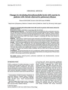
(B) Large-sized pressure vessel conventionally, the pressurized bubbling type ?uid
combined-cycle electric generating system in Which coal is converted into gas and a re?ned gas puri?ed by removing
izedbed boiler comprises square combustors 146 accommo
dust particles is supplied to a gas turbine. The coal gasi?
dated in a circular pressure vessel 145 in a plan vieW as shoWn in FIG. 14. Therefore, a useless space is de?ned betWeen the combustors 146 and the pressure vessel 145,
cation combined-cycle electric generating system, incorpo rating an air-cooled gas turbine Which uses exhaust gas of
1300° C., has a target ef?ciency of 47.1% at a generating end.
that the bed material storage container is necessary to Withdraw and return the high-temperature ?uidized medium from and into the combustor, it is not easy to Withdraw and return the ?uidized medium at high temperature and pressure, and agglomeration tends to occur When the ?uid ized medium of high heat capacity are taken into and out of the bed material storage container. under pressure, the heat transfer tube in a splash zone of the ?uidized bed is more subject to erode than that in the
research and development trends toWard pressurized ?uidized-bed boilers (PFBC) that make it possible to con
generation to meet the load. When the heat transfer surfaces of the heat transfer tube are exposed to the gas, the heat transfer coef?cient thereof is loWered, and hence the amount of heat recovered is loWered. Since the exhaust gas emitted
from the ?uidized bed is cooled by the exposed heat transfer surfaces, the temperature of the exhaust gas supplied to the gas turbine is loWered, thus reducing the output energy of the
utilizing coal combustion to generate a clean energy. To meet such a demand, atmospheric ?uidized-bed boilers
electric generation have been developed because a stable energy supply cannot be achieved by pulverized coal boilers
bubbling type ?uidized-bed boilers. HoWever, the pressurized bubbling type ?uidized-bed boiler has the folloWing disadvantages. (A) Disadvantage in load control The pressurized bubbling type ?uidized-bed electric gen erating system is controlled to meet a load imposed thereon
into a gas turbine.
conjectured that coal Will have to be relied upon as a major energy resource because greater dependency on nuclear and oil energies is not favorable at present. To suppress carbon dioxide emission and provide a substitute for oil and nuclear poWer, there has been a demand for a highly ef?cient,
a capacity over 80 MWe Which are in operation as demon stration or commercial models are made up of pressurized
resulting in a large-sized pressure vessel and increasing the
On the other hand, the pressurized bubbling type
construction cost of the boiler. In other to solve the above problems, Mr. Jim Anderson
?uidized-bed boilers With a capacity over 80 MWe are already in operation overseas as demonstration or commer
bling type ?uidized-bed boiler in principles and design
55
of A.B.B Carbon, A.B. proposed a certain pressurized bub
cial models and, in addition, has an advantage that a des
philosophy for a 350 MWe PFBC module. The pressurized bubbling type ?uidized-bed boiler is constructed by com bining diamond-shaped three combustors 147 to form a hexagonal pro?le in a plan vieW as shoWn in FIG. 15. Assemblage of the combustors 147 Which is brought close to
ulfurization equipment is not required. HoWever, the coal gasi?cation electric generating system is superior to the
pressurized ?uidized-bed combined-cycle electric generat ing system in ef?ciency. Thus, a topping-cycle combined electric generating system Which has advantages of both systems and higher ef?ciency has been researched. The topping-cycle combined electric generating system, comprises a gasi?er in Which coal is decomposed into coal
65
a circular shape is accommodated in a circular pressure vessel 145. Auseless space betWeen the combustors 147 and the pressure vessel 145 is reduced and the pressure vessel is downsized. The reason for the above structure is that
US RE37,300 E 3
4
arrangement of heat transfer tubes is complicated in the
chamber having an air diffusion device provided at the
pressurized bubbling type ?uidized-bed boiler having a cylindrical combustor. Further, since the bed material storage container and pipes
bottom of the combustor and adapted to inject ?uidizing air upWardly under a mass ?oW that is at least greater at one side
than that at another side; an inclined partition Wall provided above a portion of the air diffusion device Where the mass ?oW is greater so as to interfere With the upWard ?oW of the
are necessary to WithdraW and return the high-temperature
?uidized medium from and into the combustor, housing of bed material storage container and the pipes inside the pressure vessel makes the pressure vessel large. (C) Erosion of the heat transfer tube In the conventional pressurized bubbling type ?uidized bed boiler, the heat transfer tube is more subject to erode, because the heat transfer tube is disposed in the ?uidized bed Where the ?uidized medium is intensely ?uidized. Therefore, the heat transfer tube is required to have surface treatment like thermal spraying.
?uidizing air and thereby to de?ect the air toWards a portion above the another side of the air diffusion device Where the mass ?oW is smaller; a thermal energy recovery chamber
partitioned from the main combustion chamber by the inclined partition Wall; a heat transfer surface means pro vided in the thermal energy recovery chamber for a passage of a heat receiving ?uid therethrough; an air diffuser pro vided at a loWer portion of the thermal energy recovery 15
(D) Complicated fuel supplying system In the conventional pressurized bubbling type ?uidized bed boiler, fuel such as coal is insuf?ciently dispersed horizontally in the ?uidized bed. In order to avoid nonuni form combustion, many fuel feeding pipes must be installed in the boiler, resulting in a complicated fuel supplying system. Further, it is difficult to supply fuel such as coal to
the injected mass ?oW is smaller so that a ?uidized medium
each of the fuel feeding pipes uniformly. Unbalanced supply of fuel causes nonuniform combustion and generates
25
agglomeration, resulting in shutdoWn of the boiler. (E) Wear of limestone In the conventional pressurized ?uidized-bed electric gen erating system, limestone is mixed With the ?uidized
Without su?iciently contributing to the desulfurizing action. The conventional pressurized ?uidized-bed electric gener
air diffuser in the thermal energy recovery chamber causes the ?uidized medium Within the recovery chamber to descend in a state of a moving bed for circulation to the main combustion chamber, and combustion gas from the main combustion chamber and the thermal energy recovery cham ber is mixed in the free board. According to a preferred embodiment, the boiler com
ating system fails to achieve a high desulfurization rate that
are required by poWer plants. The conventional pressurized
bubbling type ?uidized-bed requires plenty of desulfurizing agent in order to obtain high desulfurization rate, and then produces a vast amount of ashes.
On the other hand, in the topping-cycle combined electric generating system, the ?uidized-bed boiler Which is used as an oxidizer has the same disadvantages as mentioned above.
Further, a ?xed-bed gasi?er is disadvantageous in that coal tar remains in the ?xed bed, and an entrained ?oW 45
HoWever, the bubbling type ?uidized-bed gasi?er has the same disadvantages as enumerated in (A)—(D). SUMMARY OF THE INVENTION
It is therefore an object of the present invention to provide a pressurized internal circulating ?uidized-bed boiler for a
descends and diffuses Within the moving bed, and a circu lating ?uidized bed is formed above the portion of the air diffusion device Where the mass ?oW of the ?uidizing air is greater so that the ?uidized medium is intensely ?uidized and Whirled toWards a position above the moving bed and a part of the ?uidized medium is introduced into the thermal energy recovery chamber beyond an upper portion of the
inclined partition Wall, the formation of the moving bed and the circulating ?uidized bed is effected by regulation of the amount of air injected upWardly from the air diffusion device, and regulation of the ?uidizing air injected from the
medium for desulfurization. HoWever, the limestone Wears rapidly, and is scattered as ash from the dust collector
gasi?er is disadvantageous in that ash-sticks occurs because of high temperature reaction. On the contrary, a ?uidized bed gasi?er has advantages that coal tar does not remain, ash-sticks does not occur and desulfurization is performed in the ?uidized bed, because it is in operation at the interme diate temperature of the above tWo types of gasi?er.
chamber; and a free board provided integrally above the main combustion chamber and the thermal energy recovery chamber; Wherein the thermal energy recovery chamber is communicated at upper and loWer portions thereof With the main ?uidized bed combustion chamber, a moving bed is formed above the portion of the air diffusion device Where
55
combined-cycle electric generating system, Which can be controlled to meet a load Without varying the height of a
?uidized bed, prevents agglomeration, minimize the emis
prises at least one secondary air supplying nozzle for sup plying a secondary air into the free board so that combustion gas from the main combustion chamber and the thermal energy recovery chamber is mixed and unburned combus tible materials in the combustion gas is combusted. Further, the boiler comprises screening means provided betWeen the main combustion chamber and the thermal energy recovery chamber for preventing combustible materials having a large grain size from entering the thermal energy recovery chamber, and for alloWing combustion gas from the thermal energy recovery chamber to pass therethrough While regu lating stream of the combustion gas. According to another aspect of the present invention, there is provided a pressurized internal circulating ?uidized bed boiler for use in a combined-cycle electric generating system, comprising: a pressure vessel; a combustor disposed in the pressure vessel and having a cylindrical outer Wall; a main combustion chamber having an air diffusion device provided at the bottom of the combustor and adapted to inject ?uidizing air upWardly under a mass ?oW that is at
sion of carbon monoxide and nitrogen oxide, and can
least greater at an outer side than that at a central side; a
increase a limestone utilization ratio and a desulfurization
partition having a cylindrical partition and a conical partition
rate.
formed at an upper portion of the cylindrical partition, the conical partition being provided above a portion of the air
According to one aspect of the present invention, there is
provided a pressurized internal circulating ?uidized-bed boiler for use in a combined-cycle electric generating system, comprising: a pressure vessel; a combustor disposed in the pressure vessel; a main ?uidized bed combustion
diffusion device Where the mass ?oW is greater so as to 65
interfere With the upWard ?oW of the ?uidizing air and thereby to de?ect the air toWards a portion above the central side of the air diffusion device Where the mass ?oW is
US RE37,300 E 5
6
smaller; an annular thermal energy recovery chamber par
titioned from the main combustion chamber by the partition;
having a cylindrical outer Wall; a main combustion chamber having an air diffusion device provided at the bottom of the
a heat transfer surface means provided in the thermal energy recovery chamber for a passage of a heat receiving ?uid
under a mass ?oW that is at least greater at an outer side than
therethrough; and an air diffuser provided at a loWer portion of the thermal energy recovery chamber; Wherein the ther mal energy recovery chamber is communicated at upper and loWer portions thereof With the main ?uidized bed combus tion chamber, a moving bed is formed above the portion of the air diffusion device Where the injected mass ?oW is smaller so that a ?uidized medium descends and diffuses
combustor and adapted to inject ?uidiZing air upWardly that at a central side; a partition having a cylindrical partition and a conical partition formed at an upper portion of the
cylindrical partition, the conical partition being provided above a portion of the air diffusion device Where the mass ?oW is greater so as to interfere With the upWard ?oW of the 10
?uidiZing air and thereby to de?ect the air toWards a portion above the central portion of the air diffusion device Where
Within the moving bed, and a circulating ?uidiZed bed is formed above the portion of the air diffusion device Where
the mass ?oW is smaller; an annular thermal energy recovery
the mass ?oW of the ?uidiZing air is greater so that the
the partition; a heat transfer surface means provided in the
?uidiZed medium is actively ?uidiZed and Whirled toWards a position above the moving bed and a part of the ?uidiZed medium is introduced into the thermal energy recovery chamber beyond an upper portion of the inclined partition Wall, the formation of the moving bed and the circulating ?uidiZed bed is effected by regulation of the amount of air
chamber partitioned from the main combustion chamber by 15 thermal energy recovery chamber for a passage of a heat
receiving ?uid therethrough; and an air diffuser provided at a loWer portion of the thermal energy recovery chamber; Wherein the thermal energy recovery chamber is communi cated at upper and loWer portions thereof With the main ?uidiZed bed combustion chamber, a moving bed is formed above the portion of the air diffusion device Where the
injected upWardly from the air diffusion device and regula tion of the ?uidiZing air injected from the air diffuser in the
injected mass ?oW is smaller so that a ?uidiZed medium
thermal energy recovery chamber causes the ?uidiZed medium Within the recovery chamber to descend in a state
of a moving bed for circulation. According to a preferred embodiment, the boiler com
25
prises a free board provided integrally above the main combustion chamber and the thermal energy recovery chamber, Wherein combustion gas from the main combus tion chamber and the thermal energy recovery chamber is miXed in the free board. Further, the boiler comprises at least one secondary air supplying noZZle for supplying a second ary air into the free board so that combustion gas from the main combustion chamber and the thermal energy recovery chamber is miXed and unburned combustible materials in the combustion gas is combusted. According to a preferred embodiment, the boiler com
inclined partition Wall, the formation of the moving bed and the circulating ?uidiZed bed is effected by regulation of the amount of air injected upWardly from the air diffusion device and regulation of the ?uidiZing air injected from the air 35
diffuser in the thermal energy recovery chamber causes the ?uidiZed medium Within the recovery chamber to descend in a state of a moving bed for circulation.
According to another aspect of the present invention, there is provided an integral type of in?uidiZed-bed boiler for use in a topping-cycle compound electric generating system, comprising: a cylindrical outer Wall; a cylindrical
prises screening means provided betWeen the main combus tion chamber and the thermal energy recovery chamber for
preventing combustible materials having a large grain siZe from entering the thermal energy recovery chamber, and for alloWing combustion gas from the thermal energy recovery chamber to pass therethrough While regulating stream of the combustion gas. Further, the boiler comprises a second air diffuser provided at the connection opening for enabling ?uidiZed medium to be actively ?uidiZed in the connecting
descends and diffuses Within the moving bed, and a circu lating ?uidiZed bed is formed above the portion of the air diffusion device Where the mass ?oW of the ?uidiZing air is greater so that the ?uidiZed medium is actively ?uidiZed and Whirled toWards a position above the moving bed and a part of the ?uidiZed medium is introduced into the thermal energy recovery chamber beyond an upper portion of the
partition provided concentrically With the cylindrical outer Wall; a gasi?er formed inside the cylindrical partition; an oXidiZer formed betWeen the cylindrical outer Wall and the cylindrical partition; an air diffusion device provided at the 45
bottom of the gasi?er and adapted to inject ?uidiZing air upWardly under a mass ?oW that is at least greater at an outer side than that at a central side; a conical partition formed on
opening. According to a preferred embodiment, the heat transfer
the cylindrical partition, the conical partition being provided
surface means comprises heat transfer tubes Which are installed in a radial pattern, the heat transfer tubes are divided into a plurality of blocks for use as a block of
above a portion of the air diffusion device Where the mass ?oW is greater so as to interfere With the upWard ?oW of the
?uidiZing air and thereby to de?ect the air toWards a portion above the central portion of the air diffusion device Where
evaporating tubes, a block of steam superheating tubes and a block of steam reheating tubes. Further, the boiler com prises a dust collector provided in a passage of combustion
gas, Wherein ?ying ashes caught by the dust collector is
the mass ?oW is smaller; an air diffuser provided at a loWer 55
returned to the thermal energy recovery chamber through an
opening formed in the pressure vessel. According to another aspect of the present invention, there is provided a topping-cycle compound electric gener ating system including a gasi?er for generating a gas and char, an oXidiZer for combusting the char to produce com
portion of the oXidiZer; and a ?rst free board de?ned above the gasi?er and a second free board de?ned above the oXidiZer, the ?rst and second free boards are separated from each other by the cylindrical partition so that a gas produced by the gasi?er and combustion gas from the oXidiZer are
separately discharged toWards the outside; Wherein the oXi diZer is communicated at intermediate and loWer portions thereof With the gasi?er, a moving bed is formed above the portion of the air diffusion device Where the injected mass
bustion gas, and a gas turbine Which is driven by a high
temperature gas produced by combusting miXture of the
?oW is smaller so that a ?uidiZed medium descends and
generated gas and the combustion gas, at least one of the
diffuses Within the moving bed, and a circulating ?uidiZed bed is formed above the portion of the air diffusion device
gasi?er and the oXidiZer comprising a pressuriZed internal circulating ?uidiZed-bed boiler Which comprises: a pressure vessel; a combustor disposed in the pressure vessel and
65
Where the mass ?oW of the ?uidiZing air is greater so that the
?uidiZed medium is actively ?uidiZed and Whirled toWards
US RE37,300 E 7
8
a position above the moving bed and a part of the ?uidized medium is introduced into the oxidizer beyond an interme
injected from the air diffuser in the oxidizer causes the
installed in a radial pattern in the plan vieW. Abottom face of the main combustion chamber is conical in shape and is provided With air diffusion nozzles Which ?uidize the bed material in the main combustion chamber. The volume of air to be injected from these air diffusion nozzles is controlled in such a manner that the ?uidizing gas velocity Within the range of a concentric circle Which has about half the
?uidized medium Within the oxidizer to descend in a state of
diameter of the main combustion chamber sloWs to a veloc
diate portion of the partition Wall, the formation of the moving bed and the circulating ?uidized bed is effected by regulation of the amount of air injected upwardly from the air diffusion device and regulation of the ?uidizing air a moving bed for circulation. With the above arrangements, the present invention offers
10
annular area surrounding the concentric circle achieves a
the folloWing operations or advantages: (1) Since the main combustion chamber and the thermal energy recovery chamber are functionally separated from each other Within the combustor, the boiler can be controlled to meet a load simply by varying the overall heat transfer coef?cient of the heat transfer tubes through adjustment of
high velocity of approximately 4 to 12 times the minimum
?uidizing gas velocity 15
Because of this arrangements, the bed material (?uidized medium) in the ?uidized bed of the main combustion
25
combustion chamber and then sloWly disperses in all direc tions along the conically shaped bottom face to reach the surrounding annular area, Where due to the existing intense ?uidization, the ?uidized medium is forced to bloW upWard and moves along the inner face of the cylindrical partition. At this time, since the conical partition is formed at the upper section of the cylindrical partition, the bloWing force is concentrated to ?nally achieve its maximum level When reaching the surface of the ?uidized bed Where the ?uidized
chamber starts to descend in the central part of the main
the amount of air introduced into the thermal energy recov
ery chamber, rather than by varying the height of the ?uidized bed in the combustion chamber. Therefore, no
complex process and equipment is necessary to take the ?uidized medium into and out of the combustion chamber and the thermal energy recovery chamber, and no agglom eration is generated as the ?uidized medium ?oWs into and out of the main combustion chamber and the thermal energy recovery chamber. Since the temperature of the ?uidized bed
medium forcibly reverses its course by reactive force to thus disperse horizontally in all directions as Well as partly
is kept at a constant level even When the load on the boiler
varies, the boiler can be operated under a temperature
upWard direction.
condition optimum for the suppression of NOx, SOx, and
As a result of this action, a large quantity of ?uidized medium (bed material) ?oWs into the thermal energy recov ery chamber beyond the top of the partition, While the residual medium remaining on the surface of the ?uidized bed settles as a cylindrical ?oW in the vicinity of the central
other undesirable emissions. Inasmuch as the heat transfer
tubes are positioned only in the thermal energy recovery chamber Which is exposed to a gradual ?oW of the ?uidized medium, the heat transfer tubes are less subject to erode than Would be if they Were placed in the ?uidized bed Which is
part While entraining the surrounding ?uidized medium.
in an intense ?oW condition.
As sWirling ?oWs are developed in the ?uidized bed, the ?uidized medium does not stay stagnant in the ?uidized bed, and the fuel such as coal or petro coke is uniformly dispersed
35
When the ?uidized medium reaches the area near the central
part of the conical bottom face of the main combustion chamber, it develops a circulating ?oW moving in a hori zontal direction toWard a circumferential area. The circulat ing ?oW causes the ?uidized medium to ?oW as a dispersed
and combusted, With no agglomeration produced. Thus, ef?ciency of gas turbine is not loWered. The amount of
?oW from the central part along the conical bottom face
carbon monoxide and nitrogen oxide (NOx) produced is kept loW because the exhaust gas emitted from the ?uidized bed is not cooled by the heat transfer tubes. Further, a free board having a Wide space is de?ned above he thermal energy recovery chamber and the main combus tion chamber, combustion gas from the thermal recovery chamber and the main combustion chamber is suf?ciently mixed in the free board. Therefore, combustion gas remains in the free board for a long period of time, combustible materials are suf?ciently combusted in the free board.
ity of approximately 1 to 2.5 times the minimum ?uidizing gas velocity The ?uidizing gas velocity in the
gradually in all directions, thereby uniformly dispersing fuel and desulfurizing agent. Therefore, the combustion becomes uniform Without developing an agglomeration. The number of fuel feeding ports may be minimized, resulting in a highly 45
simpli?ed fuel supply system. Since the ?uidized medium remaining on the surface of the ?uidized bed settles as a
cylindrical ?oW in the vicinity of the central part While entraining the surrounding ?uidized medium, the fuel and the desulfurizing agent remain in the ?uidized bed for a long period of time for increased combustion ef?ciency and
Furthermore, since secondary air is supplied to the free
desulfurization ef?ciency.
board, combustion gas from the thermal recovery chamber and the main combustion chamber is fully mixed and unburned combustible materials entrained in combustion gas are suf?ciently combusted in the free board. (2) A cylindrical combustor is accommodated in a pres
A large amount of ?uidized medium ?oWs over the partition and enters the thermal energy recovery chamber. A comb-toothed screen is disposed in the free board above an upper portion of the main combustion chamber and the thermal energy recovery chamber in surrounding relation to the thermal energy recovery chamber. The comb-toothed
55
sure vessel Which can retain higher inner pressure than atmospheric pressure. The pressure vessel may be of a
screen is effective to prevent a solid fuel such as coal
particles of large diameter from entering the thermal energy
cylindrical shape or a spherical shape. Inside the ?uidized bed of the cylindrical combustor, there is provided a cylin drical partition, With a tapered upper section constituting a conical partition, Which separates the main combustion chamber from the thermal energy recovery chamber. The conical partition serves to interfere With the upWard ?oW of the ?uidizing air and to thereby de?ect the air toWards the central part of the main combustion chamber. In the thermal energy recovery chamber, immersed heat transfer tubes are
recovery chamber. Accordingly, the development of an agglomeration can be avoided in the ?uidized bed in the thermal energy recovery chamber though the ?uidized bed is sloWly ?oWing at a speed that is less than tWice the mini mum ?uidizing gas velocity. The screen serves as a baf?e 65
against combustion gas generated in the thermal energy recovery chamber, thus permitting the combustion gas to be mixed and agitated suf?ciently With combustion gas gener