HOLT GUN TRACTOR MAKES £150,000
NOVEMBER 2015
ATHOME 'CANADASENTINEC DEBUTS IN HOME
No. 309
IN
BEDS
LOOKING
AFTER NUMBER ONE
COUNTY
A VISIT TO NORMAN BUNCOMBE'S WORKS IN
1970 Originally published in the Old Glory Magazine, November 2015 and provided with permission from the editor. http://www.oldglory.co.uk/
==INDUSTRIAL
HERITAGE
ABOVE:On the banks of the Ohio river, the Old River Station of the Greater Cincinnati Water Works is an active pumping facility using electric pumps but the impressive building also houses four extraordinary historic water pumps with colossal steam engines. LELANDL HITE RIGHT:The nearly completed station of the Cincinnati Water Works (CWW) began pumping water in 1906. On the right is the elevated coal storage building supported by steel beams which held a 300-day supply in 114 pocket hoppers. This and the chimney were dismantled soon after the pump house was decommissioned in 1963. Delightful architectural forms were used for functions both inside and outside the buildings ..CWW ARCHIVE 421 NOVEMBER 2015 OLD GLORY
First operating in 1906, the four triple-expansion steam engines were arranged in a quadrangle inside a circular pump house at River Station. LELANDL HITE
Assembly of the 24ft diameter, 4O-ton, dual flywheels is shown prior to insertion ofthe'dog bone'locking keys. CWW ARCHIVE
Leland L Hite, of the organisation Cincinnati Triple Steam based in Cincinnati,
Ohio, tells of the extreme difficulties associated with the installation of a pumping engine system of gigantic proportions on a capricious river that dictated its need
O
ften called the world's largest steam engines, weighing in at over 1400 tons and with a height of 104 feet, the triple-expansion engines for pumping water at what is now known as the 'Old' River Station of the Cincinnati Water Works ran reliably for 57 years. At 1000hp, they are not the most powerful of engines since smaller engines with larger horsepower were used at Main Station in Cincinnati and also elsewhere in the world. But what caused the
engines to become the largest ever built? Well, certainly no one sat down and said: "Let's construct the largest engines we can:' Instead, prior to the 1929 completion of navigation control locks and dams on the Ohio river that boosted minimum navigation depth to nine feet - the draft required to tow coal barges - the river level often changed from less than two feet to more than 75 feet in the autumn and spring ... and very quickly at times! When construction of the new water works began in
California, Ohio, during 1898, this large dynamic range of river level caused a challenging set of design considerations for pumping water to the city of Cincinnati. The first question was how to guarantee air would not enter the pump chamber when the pump took suction at low water levels, thus causing dangerous pump cavitation and water hammer in the distribution system. Secondly, it was equally important to keep the steam cylinders dry during periods of high water, should the station become flooded, which happened following
the first year of operation in 1907 - with a river level of 80 feet above normal- and again in 1937. Locating the base of the engine 5lh feet below the floor of the Ohio river, thereby allowing water to gravity feed into the suction chamber and purge its air pockets, even at the lowest river level, solved the first problem. Stretching the engine to 104 feet in height satisfied the 'dry head' requirement and produced an engine with 11 working decks; these being accessible by elevator and two spiral staircases. J OLD GLORY NOVEMBER 2015143
_INDUSTRIAL
HERITAGE
Dual bevel gear sets were used to transfer power from the crankshaft to the eccentric shaft. The wooden teeth used for the large gear to provide a small amount of shock absorption in the steel and cast iron engine can be seen. These help eliminate the whirling gear noise. LELANDL HITE
The bottom dial on the gauge panel is a counter clockwise rotating piston position indicator (CCWPPI), displaying the real-time location for all three steam pistons and pump plungers. The starting procedure changed in response to the location of the piston in the high-pressure cylinder. LELANDL HiTE
The quad connecting rods from the crosshead to the pump plunger straddle the crankshaft and the crank web. LELANDL HiTE
A DAUNTING
CHALLENGE While the design of such tripleexpansion steam-powered water pumping engines was not new in the late 1800s, no one had ever built an engine of this size. Facing a daunting challenge, the Cincinnati Water Works remained diligent in their quest for a successful design. Fifteen bids from eight engine manufacturers in December 1897 resulted in a contract being placed with Lane & Bodley Co of Cincinnati to supply and erect four vertical triple-expansion engines, each of 30 million gallons daily pumping capacity, the necessary boiler equipment and a 30-ton circular travelling overhead electric crane. Two years passed during which no plans entirely acceptable were submitted, and, with a ruling against them by the Ohio 441 NOVEMBER 2015 OLD GLORY
Supreme Court in January 1900, Lane & Bodley's contract for $514,000 was cancelled for 'failure to comply: Two successive attempts to acquire a successful proposal produced 14 responses from four companies, all rejected as unsatisfactory, causing considerable anxiety about the feasibility of the project. Eventually, three years later, a review of 11 proposals from four companies revealed several bids that were close to meeting the requirements. Most agreeable to making design changes in real time and at no additional cost, the Camden Iron Works of Camden, New Jersey, was happy to be the chosen vendor. Contracted to supply four engines with appropriate boilers at a cost of $807,500, the foundry began this task in January 1901. The project proceeded quickly. Two and a half years later, with most of the
Removed from the engine for display purposes is one of the 14 poppet valve cages in each pump. LELANDL HiTE
in the early 1900s, workers whose task was to oil the engines accessed various decks using this five-storey spiral staircase accessible from the engine's eccentric deck. LELANDL HiTE foundry work finished, two-thirds of the castings were machined and half of each engine was constructed on site in Camden. The engines were erected and hand rotated at the iron works to ensure that moving parts functioned as designed. Steam was never applied while the engines were in Camden. Subsequently, in June 1903, after a long legal battle, Lane & Bodley had to pay back $65,000 of the $303,000 paid to them from their failed efforts to design and build the engines. Limited navigation of the Ohio river affected fuel supply, causing a demand for the highest possible efficiency from the station to minimise coal consumption. The quartet of engines were designed by John H Lewis from R D Wood & Co in Philadelphia and built in its foundry, the Camden Iron Works (N]), located directly
Components for one of the 6700 poppet valves in the pumps include a brass seat and securing screw, a rubber washer - but the spring is copper. LELANDL HiTE
across the Delaware River from Wood's premises. These tripleexpansion 1000hp engines sported a modern efficiency design. Each cylinder, respectively 29in, 54in, and 82in in diameter, was encased with a steam jacket and both receivers supplied with reheaters. Efficient Corliss valves with dash pots were specified for the high-pressure cylinder and the steam side of the intermediate pressure cylinder, while balanced poppet valves were used for the low-pressure cylinder and the exhaust side of the intermediate. Initial start-up found Engine No 2 with a cracked head on the intermediate pressure cylinder and, after replacement, no major failures occurred to the four engines in 57 years of operation. Babbitt (white metal) bearings were occasionally scraped and oil grooves cleaned but none required renewal.
Running quietly was a common characteristic for a tripleexpansion condensing engine. R D Wood & Co further enhanced the muted sound by incorporating wooden teeth in the two large gears for the dual bevel gear sets that transferred power from the crankshaft to the eccentric shaft. Only a minor clicking sound remained from the knock-off cams which operated the Corliss valve as the engine ran at its full speed of 1S1rpm. The wooden teeth also provided a small amount of shock absorption in an otherwise all steel and cast iron engine. Why the engines were never designed to start utilising a barring motor is a mystery. More often than not, steam applied to the high-pressure cylinder would turn the engine but occasionally the engine would stop with the high-pressure piston at top dead centre for head end or crank end and require extra effort to start the pump. Under this condition, the first receiver was charged to 34psi in an effort to move the intermediate-pressure piston. The procedure occasionally required the 139ft head pressure to be taken off the pump plunger. On rare occasions, when all such
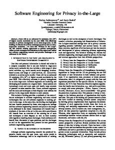
River Station Pump House Greater Cincinnati Water Works Lantern frame covered with "S" tile conical roof Riveted and caulked steel liner Romanesque Revival Architectural Style Circular Sawed Rock-Faced and Fine-Pointed Dolic Dimensioned Bedford Limenstone Solid Wood Caisson Deck
"shoes with Excavation Chambers~~~~~~§~~ ~~~!!:===~
\.II...
III"D:;;i?
A cutaway view of the circular pump house features structural components. LELANDL HITE attempts had failed, a large rope was attached from the flywheel to the overhead crane to nudge the engine into rotation. When live steam was applied like this, two workers stood by with sharp axes to cut the rope immediately the engine started rotating.
==========~========= At 15rpm, each engine moved six tons of water into its chambers every two seconds
==========~=========
THE ENGINES Each engine drew 1S0psi of dry processed steam from two fourdrum Sterling water-tube boilers fitted with Foster superheaters and Green's Economisers, increasing boiler efficiency to over 78%. Firebox draft was forced from two 8Sin steam-powered Buffalo Forge fans into a 175ft x 8ft chimney. 'Coal to water' efficiency (duty) for two boilers and an engine was thus 156,315,000 ft-lb of work per 100lb of Pittsburg 'nut and slack' coal, or 1,883,000 gallons lifted one foot per 100lb of burnt coal. Scale and unwanted chemicals
were removed from the condensate flowing from the surface condenser using a large de-aerating plant. Each engine housed its own wet air pump to evacuate air from the surface condenser, a boiler feed water pump and a sump pump. Collected in dual condensate storage tanks, boiler feed water originating in the hot well for the surface condenser was pumped through the de-aerating plant, the exhaust heater and the Green Economiser (preheating feed water using boiler flue gases) prior to entering the boiler at 2100EI
An 0 S Kelly traction engine assisting a mule team to move a 3600lb Bedford limestone block to River Station after heavy rains. Between 1890 and 1891, Oliver Kelly employed designing engineer Edward TWright, an Englishman who was an apprentice at Aveling & Porter in England. Wright's influence may be detected in the design of the Kelly engine. CWW ARCHIVE OLD GLORY NOVEMBER 2015145
.
INDUSTRIAL
HERITAGE
Resting on 7ft wooden beams, the tapered edge for the caisson began being erected concurrently with the first layer of deck timbers. CWW ARCHIVE Each engine moved its required 30 million gallons per day into two holding reservoirs providing a supply lasting several weeks in 1906 in the event of the cessation of pumping. The 96in stroke from each steam piston was directly connected to its nickeliron pump plunger measuring 37Y>in diameter and 14ft long. The displacement-type pump took suction on the upstroke and discharged 450 gallons on the downstroke - 1350 gallons per engine per revolution. At l Srpm, each engine moved six tons of water into its chambers every two seconds. Enormous forces thus resulted from starting and stopping six tons of water on each half rotation of the engine and this
caused the need for large force chambers (air chambers) on both the suction side and the discharge side to smooth out pumping pulsations prior to the water's distribution. Twenty-four tons of water moved through the station for every rotation of the dual 40ton flywheels on each engine! The poppet valves used a rubber disc against a brass seat for both the suction and discharge side of the pump and 50% more valves were included on the suction and discharge side than were actually required for the smooth flow of water, thus minirnising maintenance demands. Annually, each pump was dewatered, enabling a worker to crawl inside the pump chamber to inspect its
1680 poppet valves - more than 6700 for the complete pumping station. The brass seat often required refacing, using the station lathe, as a result of debris being trapped between the rubber and the brass seat which scored the brass but not the flexible rubber. As with the engines, the Ohio river itself dictated coal storage designs at the River Station. There was always a supply of pumping water, even at low river levels but year-round navigation was not possible. Because a coalcarrying tow barge required a draft of nine feet, navigation from the fuel supply in Pittsburg was restricted to a few months each year, depending on low river levels and ice. Good planning provided
High water in 1937 flooded the station, preventing it working for 11 days. CWW ARCHIVE 461 NOVEMBER 2015 OLD GLORY
Six-ton pie-shaped cast iron segments formed a 4200-ton ballast around the 10ft diameter standpipe to assist in holding the floor level and to prevent the building from floating during periods of high ground water. CWW ARCHIVE a 300-day supply (8000 tons) of dry coal, stored seven feet above ground in 114 elevated pocket hoppers. Even with navigation control dams and locks which were installed by 1929, low river levels over prolonged periods prevented coal delivery, causing hoppers to be depleted. Thus, in the last three months of 1930, instead of river delivery, all the coal burned had to come in by rail. Daily usage averaged 26 tons of coal that was moved to the boiler house from the storage hoppers using a 19in wide narrow-gauge rail system. This was equipped with several two-ton boiler charging cars powered by a small electric locomotive, about the size of a golf cart, called the Dinky which ran on Edison batteries. A coal pusher dumped the coal on the floor in front of each boiler from where shovellers moved it into the stoker hopper. Boiler ash cars were moved using the same locomotive. Yet again, Ohio river dynamics influenced design decisions regarding the shape and size of the pump house. Because the floor of the building was to rest 105 feet below ground level in soil experiencing a high ground water level, a circular structure was best suited to withstand the 20,000 tons of hydraulic pressure pushing in and up on the building. The bottom of the pump pit wall, laid from Bedford limestone, is 15 feet thick and tapers to four feet in thickness at ground level, with the inside wall being plumb and fine pointed. Fitted with a riveted and caulked steel liner resting two feet from the inside diameter, the resulting cylinder provided for watertight construction.
THE BUILDING Because the extreme weight of the four engines was well over 6000 tons, the pit floor required a high-strength design. A familiar construction technique employed to build wooden reservoirs at the water works in the 1800s used 12in square air-dried and machined white oak timbers that were closely spaced and bolted. Full of water, the wood expanded to seal the joints making an excellent storage container. Building a sturdy floor for the circular pump pit followed the same procedure but used criss-crossed timbers, bolted and closely spaced, to become a circular disc - 128 feet in diameter and 12 feet in thickness. Constructed in 12 months, this was a sizeable chunk of timber! Sinking the pit floor required 36 excavation chambers under the 12ft caisson floor. Workers in each compartment removed sand and clay that was hoisted and stored on the floor surface to become ballast for lowering the centre of the pit floor. As the excavation progressed and the floor sank into the ground, limestone blocks were laid to form the outer wall, providing sufficient weight to lower the caisson. Most of the blocks were installed at
ground level synchronically as the pit floor lowered. Six months passed while the caisson was lowered to 105 feet below ground level and the wall reached this level during a period oflow ground water in 1899. Becoming obvious from the movement of the caisson as the sinking operation progressed, the anticipated weight of the engine
This side elevation shows the arrangement of the pump plunger and the intake force chamber to the rear of the engine. LELANDL HITE
In this front elevation view of one of the engines, the arrangement of the headers connecting the intake and discharge ports for all three pumps can be seen, as well as the wet air pump at the lower right-hand side. LELANDL HITE
Inclined dual narrow-gauge railway tracks (left) allowed one coal car to ascend to the hoisting house while another descended. Outlets for the 114 pocket hoppers in the steel-supported coal storage building, each holding 70 tons of coal, are some 7ft from the ground. CWW ARCHIVE
..
house and engines would not be sufficient to prevent shifting of the caisson. It did not prove feasible to rest the caisson on bedrock and thus, as a result, the station had the undesirable potential to float during periods of high river levels from the 20,000 tons of hydraulic pressure caused by high groundwater. With the caisson excavation complete, sand ballast was removed from the deck floor in December 1899. Shortly after this and prior to the installation of the engines, the winter ground-water level increased and the 12ft-thick wooden caisson deck deformed, taking the shape of an inverted ice-cream cone. The centre rose 3%in as the wall edge fell 1Y2 in; a catastrophic surprise .to the engineering staff and its action prevented the engines being installed. With the engines not in situ, a disproportionate amount of weight (15,000 tons) from the limestone wall rested on the outermost 25% of the caisson deck. This imbalance had a tendency to cause the caisson to sink at the outermost edge and rise at the centre. As the dry caisson absorbed water, extreme radial pressure toward the centre from the expansion of the closely spaced and bolted timbers caused enormous forces. Dry white oak can easily expand 5% or more when saturated with water. The 10ft diameter centre hole for the standpipe acted to relieve inward pressure from the moisture-laden expanding wood. Hydraulic pressure from high river levels in December 1899 then provided the necessary force to nudge the
"
highly stressed caisson upwards in the middle. Five years passed before the pumping station's floor returned to its original configuration. An unplanned 4200-ton cast iron ballast wall was placed around the standpipe for additional centre located weight but even that didn't push the centre downwards. Eventually, engine castings were randomly scattered about the floor and the pit was flooded to a depth of 34ft; this action causing an additional 12,440 tons weight which restored the floor to flatness. All four engines were rapidly assembled without regard to alignment or accuracy to place weight on the caisson. Following that, each engine was individually reassembled for a precision fit. Today, the engines still help to preserve the flatness of the floor during periods of high water. Extreme river levels do cause deliberate flooding of the pump pit with one and half feet of water for every one foot the river rises. The Old River Station pumping site is a wonder worth seeing. Tours of the station are arranged through the Cincinnati Triple Steam website (www.cincinnatitriplesteam.org). Plans are under way to provide a power source to turn one of the engines again and if this goal can be achieved, visitors will have the rare opportunity of witnessing the dynamism of a mammoth steam pumping engine. Grateful thanks are extended to Larry Moster, assistant superintendent of the Cincinnati Water Works, for his enthusiastic support and to Robert T Rhode for his guidance and assistance .• OLD GLORY NOVEMBER 2015147