XVI International Conference on Gas Discharges and their Applications, Xi’an (China), September 11-15, 2006
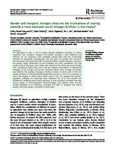
STABLE RADIO-FREQUENCY DISCHARGE WITH PURE NITROGEN AT ATMOSPHERIC-PRESSURE Hua-Bo Wang, Wen-Ting Sun, He-Ping Li, and Cheng-Yu Bao Department of Engineering Physics, Tsinghua University, Beijing 100084, China Xing Gao Beijing Center for Preventive Medical Research, Beijing 100013, China Corresponding author. H.-P. Li:
[email protected] ABSTRACT
water-cooled
Pure nitrogen radio-frequency (RF) uniform glow discharge is obtained for the first time with two planar bare water-cooled copper electrodes at atmospheric pressure. The discharge characteristics of pure nitrogen, pure helium and nitrogen-helium mixture are studied in this paper. Experiments show that helium glow discharge can operate in two modes (α mode and γ mode), whereas, up to now, pure nitrogen glow discharge can only operate in the γ mode.
atmospheric-pressure is obtained for the first time.
bare
electrodes
at
Comparisons on the discharge characteristics of pure helium, pure nitrogen and mixture of He-N2 are also presented in this study.
2. EXPERIMENTAL SETUP 1. INTRODUCTION
A schematic diagram of the experimental setup is
As a new kind of non-thermal plasma source
shown in Fig. 1. The planar-type plasma generator is
developed in recent years, radio-frequency (RF),
composed of two 5×8 cm2 planar, bare, water-cooled
atmospheric-pressure glow discharge (RFAPGD)
metal electrodes, i.e. the RF (13.56 MHz) powered
plasmas, like other atmospheric-pressure glow
top electrode and the grounded bottom electrode. The
discharges (APGD), have notable advantages over
quartz spacers are used to seal the plasma generator
the traditional low-pressure glow discharges due to
on both sides and adjust the distance between the
the removal of the vacuum system, which reduces
electrodes from 0.4 to 1.6 mm with 0.1 mm step. The
the cost, and eliminates limitations on the
plasma forming gas (He with purity of 99.99% or
dimensions of the work-piece to be treated [1]. And
better, N2 with purity of 99.999% or better, or mixture
in contrast to atmospheric-pressure dielectric barrier
of He-N2 are used in this study) is admitted into the
discharge (DBD), RFAPGD does not need dielectric
plasma generator from the left side, ionized between
layers covered on the electrodes, which results in a
electrodes, and flows out of the generator from the
much
more
right side forming low-temperature plasma jet. The
homogeneous discharge [2]. Therefore, RFAPGD
rms values and waveforms of current and voltage, as
will have broad prospects in different fields, such as
well as the current-voltage phase difference, are
etching, deposition, decontamination of chemical
measured using a current probe (Tektronix TCP202)
and biological warfare agents, etc. [1]. Up to now,
and a high voltage probe (Tektronix P5100), and are
most of the researchers use helium (or with a small
recorded
fraction of O2, CF4, etc.) as the plasma forming gas
TDS3054B). The discharge images are taken by a
(e.g. [1], [3], [4]). But for actual applications, it is
digital camera (FUJIFILM s5500). The RF power input can be expressed as Pin = Vrms ⋅ I rms ⋅ cos θ ,
lower
breakdown
voltage
and
necessary to reduce the cost of the plasma forming gas. Wang et al [5] and Laimer et al [6] obtained
on
a
digital
oscilloscope
(Tektronix
where Vrms and Irms are the rms values of voltage and
RFAPGD plasmas with Ar-1.0%O2 and pure argon
current, respectively, θ is the current-voltage phase
as working gas, respectively. Yang et al [7] reported
difference. Thus, the average power density and
the discharge characteristics for the gas mixture of
current density of the discharge zone can be written as ρ in = Pin ( A ⋅ d ) and irms = I rms A , respectively,
He-0.4%N2. In this paper, a uniform, RF glow discharge for pure nitrogen with two planar
where A and d are the area of the discharge region and 377
XVI International Conference on Gas Discharges and their Applications, Xi’an (China), September 11-15, 2006
the distance between electrodes.
Fig. 1. A schematic of the experimental setup. Similar to discharges at intermediate pressure, RFAPGD can exist in two distinctively different, but stable modes, i.e. α mode (sustained by volumetric
ionization
process)
and
Fig. 2. Images of RFAPGD at d=1.4 mm, f=13.56 MHz using copper electrodes. (a) α mode, Pin=108 W, θ=73°, χ=0, QHe=1.0 slpm; (b) α-γ mode, Pin=279 W, θ=22°, χ=0, QHe=1.0 slpm; (c) γ mode, Pin=156 W, θ=24°, χ=0, QHe=1.0 slpm; (d) γ mode, Pin=337 W, θ=42°, χ=0.5, QHe= QN2=1.0 slpm; (e) γ mode, Pin=214 W, θ=51°, χ=1, QN2=1.0 slpm.
γ mode
(ionization by secondary electrons from the electrode surfaces is important) [8, 9]. In this paper, RF glow discharge for pure nitrogen is obtained for the first time with the experimental setup shown in Fig. 1 as follows: the uniform glow discharge with He operated in α mode is obtained first; then, with increasing the input power, the discharge transfers
In this study, it is found that in a stable γ mode
into the γ mode; and then, with increasing the N2
discharge operated with He, N2 can be added into
flow rate and, at the same time, decreasing the flow
the plasma forming gas with sustaining a stable
rate of He, finally, a stable, uniform glow discharge
glow discharge, as shown in Fig. 2 (d), with
ρin=3786 W/cm3, and irms=2.3 A/cm2. For pure N2,
for pure N2 working in the γ mode is obtained when no addition of He in the plasma working gas any
the image of discharge in the γ mode is shown in
more.
Fig. 2 (e). Compared to Fig. 2 (c), a much clearer and brighter layer in the middle of the discharge region appears in the case with N2 addition.
3. RESULTS AND DISCUSSIONS 3.1 Visual description of the discharge
Because only a small fraction of the electrode area
Images of the RFAPGD operated with different gas
is covered with a discharge, the input RF power
mixing ratio χ (=QN2/(QN2+QHe)) at d=1.4 mm using
density and current density in Fig. 2 (e) becomes much larger (ρin=12170 W/cm3, irms=11.7 A/cm2).
copper electrodes are shown in Fig. 2. The volumetric homogeneous discharge (α mode) for
Figure 2 also shows that the current-voltage
pure helium at the flow rate QHe=1.0 slpm is shown
phase difference changes obviously for different
in Fig. 2 (a) with ρin=22 W/cm3 and irms=39 mA/cm2.
discharge modes and/or different working gases.
With increasing the RF input power, the coexistence
3.2 Voltage and current waveforms
of the α mode and γ mode (α-γ mode) can appear as shown in Fig. 2 (b). By disturbing the flow field artificially, a γ mode discharge can be obtained, shown in Fig. 2 (c), with higher values ρin=1420 W/cm3, irms=1.54 A/cm2, due to the significant reduction of the discharge region. 378
XVI International Conference on Gas Discharges and their Applications, Xi’an (China), September 11-15, 2006
Ref. [9], in which the distortion of the current waveform was larger than that of the voltage waveform. 3.3 Voltage-current characteristics The features of the different operation modes of RFAPGD can be identified and characterized using the relationship between the amplitudes of the discharge voltage and the RF current, which is the so-called V-I curve. In Fig. 4 (a), a V-I curve is shown
for
pure
helium
discharge
using
water-cooled copper electrodes, which indicates three different operation regimes: (1) Prior to breakdown (A-B), the RF current increases with Fig. 3. Waveforms of voltage (solid line) and current (dashed line)
increasing the voltage linearly with a nearly 90°
for discharges operated in the γ mode at d=1.4 mm, f=13.56
current-voltage phase difference. (2) Once the
MHz using copper electrodes. (a) Pin=180 W, χ=0, QHe=1.0 slpm;
applied voltage reaches the breakdown voltage, the
(b) Pin=179 W, χ=0.5, QHe= QN2=1.0 slpm; (c) Pin=172 W, χ=1,
discharge is initiated in the α mode with a little bit
QN2=1.0 slpm; (d) Pin=300 W, χ=1, QN2=1.0 slpm.
lower discharge voltage than the breakdown voltage. Then, with increasing the RF input power, the RF
The current and voltage waveforms of RFAPGD
current and discharge voltage increase linearly
operated in the γ mode for different RF input
(B-C), but with a smaller slope than that before
powers at a gap spacing of 1.4 mm are shown in Fig.
breakdown. (3) When the input power (or the RF
3. It can be seen from Fig. 3 that: (1) the current and
current) increases to a certain value, a transition to
voltage waveforms of helium plasmas operated in
the γ mode occurs (C-D). In the γ mode regime,
the γ mode are both sinusoidal, as shown in Fig.
the discharge voltage varies very small with either
3(a); (2) with the addition of N2 to the original He
increasing (D-E) or decreasing (E-F) the RF current.
plasma working gas, the waveform of the voltage
When the RF input power or the RF current is lower
shows deviation from the sinusoidal form, as shown
than a certain value, the discharge transfers from the
in Fig. 3 (b). Fast Fourier transform (FFT) shows
γ mode to the α mode (F-G).
that the waveform of the voltage exhibits 6.8%
Up to now, direct pure nitrogen discharge in α
content of the third harmonic; (3) for pure N2
mode
discharge in the γ mode, the distortions of the
using
13.56
MHz
power
supply
at
atmospheric-pressure with bare metal electrodes
voltage waveform become more significant with the
cannot be obtained in our experiment, so, we can
increase of the power input. FFT shows that the
only provide the V-I curves of pure nitrogen
content of the third harmonic for the voltage
discharge operated in the γ mode. Figs. 4(b), (c) and
waveform increases from 9.6% in Fig. 3 (c) to
(d) show the V-I curves of the pure N2 discharge in
11.9% in Fig. 3 (d); (4) compared to the distortions
the γ mode using water-cooled copper, aluminum
of the voltage waveforms, the distortions of the
and stainless steel electrodes, respectively. From
current waveforms are smaller. FFT indicates that,
Figs. 4(a)~(d), it can be seen that: (1) for the case
in Fig. 3 (d), there exists no third harmonic in the
with copper electrodes, the V-I curves are almost
current waveform, and the content of the fifth
overlapped with increasing or decreasing the RF
harmonic is only 3.6%. This phenomenon differs
current; (2) the V-I curves for increasing or
from that of the helium glow discharge reported in
decreasing the RF current cannot be completely 379
XVI International Conference on Gas Discharges and their Applications, Xi’an (China), September 11-15, 2006
overlapped for the cases with aluminum or stainless
driven by 13.56 MHz power supply. Experimental
steel electrodes; (3) for the same working gas flow
results show that helium glow discharge can operate
rate, the discharge voltage for sustaining the glow
in two stable operation modes (α mode and γ mode),
discharge of He in the γ mode is much smaller than
whereas, up to now, pure nitrogen glow discharge
that for N2 discharge.
can only work in the γ mode. And the different
As indicated in Section 1, ionization by
electrode materials have influence on the discharge
secondary electrons from electrode surfaces is very
characteristics of plasmas in the γ mode. The
important in the γ mode. So, the discharge
possibilities and methods for obtaining a uniform
characteristics are related with the electrode
glow discharge operated with N2 in the α mode need
materials due to the different values of the work
to be studied in future.
functions.
The
measured
averaged
discharge
voltages for sustaining N2 plasmas in the γ mode are
ACKNOWLEDGEMENT
284.7± 4.4 V, 269.6±4.7 V and 281.9±4.6 V for the
This work has been supported by the project
cases with copper, aluminum and stainless steel
sponsored by SRF for ROCS, SEM. The authors
electrodes, respectively.
gratefully acknowledge Prof. Xi Chen, Tsinghua University, China, for his very helpful comments, and Prof. J. Laimer, Institut für Allgemeine physik, Vienna University of Technology, Austria, for his helpful information.
REFERENCES [1]
[2]
[3]
[4]
[5]
[6] Fig. 4. V-I curves for different plasma forming gas at d=1.6 mm, f=13.56 MHz. (a) Copper electrodes, χ=0, QHe=1.0 slpm; (b) [7]
Copper electrodes, χ=1, QN2=1.0 slpm; (c) Aluminum electrodes,
χ=1, QN2=1.0 slpm; (d) Stainless steel electrodes, χ=1, QN2=1.0 slpm. [8]
4. CONCLUSIONS [9]
In this paper, a stable uniform RFAPGD operated with pure nitrogen is obtained for the first time using two bare planar water-cooled metal electrodes 380
J. Park, I. Henins, H. W. Herrmann, G. S. Selwyn, J. Y. Jeong, R. F. Hicks, D. Shim, C. S. Chang, “An Atmospheric Pressure Plasma Source”, Appl. Phys. Lett., 76, pp. 288-290, 2000. A. Schütze, J. Y. Jeong, S. E. Babayan, J. Park, G. S. Selwyn, and R. F. Hicks, “The Atmospheric-Pressure Plasma Jet: A Review and Comparison to Other Plasma Sources”, IEEE. Trans. Plasma Sci., 26, pp. 1685-1694, 1998. J. Park, I. Henins, H. W. Herrmann, and G. S. Selwyn, “Gas Breakdown in An Atmospheric Pressure Radio-Frequency Capacitive Plasma Source”, J. Appl. Phys., 89, pp. 15-19, 2001. W. C. Zhu, B. R. Wang, Z. X. Yao, and Y. K. Pu, “Discharge Characteristics of An Atmospheric Pressure Radio-Frequency Plasma Jet”, J. Phys. D: Appl. Phys., 38, pp. 1396-1401, 2005. S. Wang, V. Schulz-von der Gathen, and H. F. Döbele, “Discharge Comparison of Nonequilibrium Atmospheric Pressure Ar/O2 and He/O2 Plasma Jets ”, Appl. Phys. Lett., 83, pp. 3272-3274, 2003. J. Laimer, S. Haslinger, W. Meissl, J. Hell, and H. Störi, “Atmospheric Pressure Radio- Frequency Capacitive Plasma Jet Operated with Argon”, Proc. 17th Int. Symp. Plasma Chem., Toronto, Canada, 2005. X. Yang, M. Moravej, G. R. Nowling, S. E. Babayan, J. Panelon, J. P. Chang, and R. F. Hicks, “Comparison of An Atmospheric Pressure, Radio-Frequency Discharge Operating in the α and γ Modes”, Plasma Sources Sci. Technol., 14, pp. 314-320, 2005. Y. P. Raizer, M. N. Shneider, and N. A. Yatsenko, “Radio-Frequency Capacitive Discharges”, Boca Raton: CRC Press, 1995. J. Park, I. Henins, H. W. Herrmann, G. S. Selwyn, and R. F. Hicks, “Discharge Phenomena of An Atmospheric Pressure Radio-Frequency Capacitive Plasma Source”, J. Appl. Phys., 89, pp. 20-28, 2001.