IEEE Transactions on Consumer Electronics, Vol. 55, No. 3, AUGUST 2009
1162
Tangible Video Teleconference System Using Real-Time Image-Based Relighting Sae-Woon Ryu, Sang Hwa Lee, Sang Chul Ahn, and Jong-Il Park, Member, IEEE Abstract — This paper deals with a real-time image based relighting system for tangible video teleconference. The proposed image based relighting system renders the extracted human object using the virtual environmental images. The proposed system can homogenize virtually the lighting environments of remote users on the video teleconference, or render the humans like they are in the virtual places. To realize the video teleconference, the paper obtains the reflectance models of users in real-time using the controlled lighting system. The reflectance models of human surface are obtained by a pair of lighting sources which are turned on and off alternatively. The images with different illuminations are exploited to model the reflectance on the object surfaces. The environment map for rendering is acquired by the mirror ball images or virtual background ones. And the relighting algorithm is implemented by GPU based programming for real-time operation. According to the simulations, the proposed system estimates the reflectance models of human faces, and relights the human faces in real-time. The objects are rendered by the reflectance models and virtual environment map. The proposed system enables the users to immerse video teleconference just as they are in the virtual environments.1 Index Terms — Video teleconference, Image based relighting, environment map, reflectance model, GPU, controlled lighting
I. INTRODUCTION Thanks to the advances in rendering techniques and high performance hardware, the virtual reality (VR) systems are getting more popular in our lives [19], [20], [21]. VR systems consist of various research areas, such as mechanics, sensor network, audio-visual signal processing, and computer graphics. One important point in the VR systems is how to realize the virtual environments to fake as if the virtual objects really exist. This helps the users immerse and interact with surroundings better. Many kinds of commercial VR systems are being developed in various applications, such as game, 1 This research was supported by Ministry of Culture, Sports and Tourism (MCST) and Korea Creative Content Agency (KOCCA) in the Culture Technology (CT) Research & Development Program 2009. Sae-Woon Ryu and Jong-Il Park are with Department of Electrical and Computer Engineering, Hanyang University, Seongdong-gu, Seoul, South Korea (emails:
[email protected],
[email protected] ). Sang Hwa Lee is with Department of Electrical Engineering and Computer Science, BK21 Information Technology, INMC, Seoul National University, Kwanak-gu, Seoul, 151-742, South Korea (emails:
[email protected]). Sang Chul Ahn is with Korea Institute of Science and Technology (KIST), Seoul, Korea (email:
[email protected]). Sang Hwa Lee is the corresponding author (e-mail:
[email protected]).
Contributed Paper Manuscript received July 15, 2009
virtual training, simulation, e-learning, and so on. The tangible video teleconference is one of the VR applications by rendering virtually the illumination environments of remote users on the video conference. The users on the tangible video teleconference feel that they are in the same place, when the environment map of remote user is exploited as the background of other user. Another application in tangible teleconference is to change the background of the user such that the user is in the virtual place. In this application, the user’s appearance should be rendered naturally to assimilate into the new surrounding background. For the tangible teleconference system, the key technology is to render the object surface using different environment maps in real-time. Rendering requires reflectance characteristics of object’s surface, 3-D geometric structure of object, and environment map. The environment map is the illumination conditions surrounding the users, and changes corresponding to the background where the user is located. Reflectance model of object’s surface defines the reflection characteristics of surface on the directional light rays, and specifies how much light is reflected on the surface. 3-D geometry of object is required to calculate the reflection of light ray since the amount of light reflection depends on the angle between incident light ray and viewpoint. In the tangible video teleconference, 3-D geometric model of user can’t be obtained in real-time, thus we use only 2-D reflection model of object’s surface. The user’s surface is rendered using the new environment map and reflectance characteristics of user’s surface. The environment map is usually obtained from mirror ball images [12], [13]. This method exploits the image reflected on mirror ball surface as the multi-lighting sources (environment map) to illuminate the objects. The environment map is modeled by the locations and strengths of lighting sources on the hemisphere. The object surface is rendered by the surrounding lighting conditions which are modeled from probe image of the mirror ball. However, the reflectance model of object’s surface and 3-D information should be known in advance to render the object using the lighting environments. One method to relight object’s surface without 3-D models exploits lighting fields from multiple lighting sources, and models the reflectance of objects based on the lighting field images. The lighting field is an observed image when a light turns on [9], [10], [11]. The lighting fields consist of all observed images by the differently located lighting sources. This approach is to model the reflectance of object’s surface using the observed images corresponding to the specific directional lighting sources. The lighting fields require multilighting system to model the lighting fields of objects.
0098 3063/09/$20.00 © 2009 IEEE
S.-W. Ryu et al.: Tangible Video Teleconference System Using Real-Time Image-Based Relighting
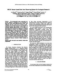
Fig. 1. The concept of proposed tangible video teleconference system. Two lights are set in front of users to model lighting fields (reflectance) of users. A mirror ball and a camera are set to obtain the environment map of user A. All the process are performed in real-time.
Another method exploits specular reflection on the object’s surface to render naturally. The specularity of surface specifies how much light reflectance occurs on the surface. The specular reflection models the lighting conditions (such as locations, spectrum of light) and material features. The objects are rendered by adding virtual specular reflection to the pure diffuse components of object’s surface. To separate specular and diffuse components, Umeyama, Wolff, and Nayar used polarization lighting [3], [4], [5]. Klinker and Lin utilized multiple images in different views [6], [7]. Shafer proposed a method based on dichromatic reflection model [8]. The dichromatic reflectance model means that the spectral distribution of specular reflection is different from that of diffuse ones. The spectral distribution of specular reflections is similar to that of lighting source. There are some results on separation of specular reflection using the dichromatic reflection model [1], [14]. However, since the methods need multiple observation images to separate the specularity, and the objects move on the video conference, it is difficult to implement the video conference systems working in real-time. In the sense of video conference, the lighting field based relighting is more suitable than specular reflectance. When we have a few lighting fields of object surface, we can render the object considering the lighting fields as reflection. In this paper, we propose an image based rendering system which deals with specifically how to model the reflectance of object’s surface. The reflectance model is obtained by the light field images which are differently illuminated by controlled lighting system. We have proposed how to approximate the reflectance of object’s surface using two controlled lighting sources [1], [14]. We render the object’s surface using the reflectance model of limited lighting sources and new environment maps. Finally, the rendering system is implemented in GPU based programming for real-time operation.
1163
Fig. 1 shows the concept of tangible video teleconference and the proposed system. User B is relit using the environment map of user A, or the users are rendered by other background images respectively. Two lights to obtain the reflection models of object are set in front of users, and a mirror ball to capture the lighting environments is used. The lights turn on and off alternatively in real-time to get the different lighting fields of moving video object. And the rendering process is performed and the video data are transmitted through the ordinary network system. All the processing including acquisition of environment map, modeling left/right lighting fields, image-based relighting, and data transmission are performed in real-time. The rest of the paper is organized as follows. Section II describes the proposed image based relighting system in detail. We will describe how to make environment map and how to model the reflectance of object surface in realtime. And we explain how the video data structure is processed in GPU and CPU. Experimental results and commercial video teleconference system are discussed in Section III. We finally conclude this paper in Section IV.
Fig. 2. The proposed rendering system. First, the reflectance models are obtained by the light field images using two lights. Then, human object is extracted from the background. The human surface is relit by the reflectance models and new environment maps.
II. PROPOSED RENDERING SYSTEM Fig. 2 shows the proposed rendering system for video teleconference. A camera and two (left and right) lights are in front of the user to obtain the reflectance models of human surface. Fig. 2 ⓐ (or ⓒ) is the image when only the left (or right) light turns on. Fig. 2 ⓑ is the image when the lights do not turn on. The reflectance model is approximated using three images. Then, human object is extracted, and is synthesized into new background images or environment maps.
IEEE Transactions on Consumer Electronics, Vol. 55, No. 3, AUGUST 2009
1164
(a)
(c)
lighting sources uniformly better. Fig. 3 compares two sampling methods of point lighting sources from probe image. In the case of AR sampling, the distribution of lighting sources is more uniform with a small number of samples. When the lighting conditions are sampled as point sources, the location of each point source is calculated in the spherical coordinates. Since the angles of lighting sources affect the rendering of object surface, we should know the position (or direction) of the lighting sources on the hemisphere. When we use the usual images as the environment map, the rectangular coordinates in the 2-D image are converted into cylindrical coordinates. And we can also change the rendering results by rotating the environment map. Note that we calculate the 3-D position of each lighting source from 2-D images. The lighting source is located at the center of subregion.
(b)
(d)
(e)
Diffuse Component
Fig. 3. Sampling methods of probe image to obtain lighting environment map. (a) LL sampling, (b) AR sampling, (c) a mirror ball image, (d) lighting environment map by LL sampling, and (e) lighting environment map by AR sampling.
A. Environment Map from Mirror Ball The environment map is the lighting conditions surrounding objects. Each point in the environment map is a lighting source to illuminate the object surface. The illumination of a surface point is integration of all the lighting sources which are on the line of sight in the environment map. The reflectance model and lighting conditions render the novel surface color with respect to solid angles of the lighting sources. The environment map is usually modeled by hemisphere since the lighting sources surround the object. In this paper, we have two kinds of environment maps. One is mirror ball image, and the other is the usual image. We exploit the mirror ball to obtain circular lighting probe images which is modeled as the 3-D environment map. The surface of mirror ball reflects the surrounding space which is considered as the lighting environment of user. The mirror ball is set in front of users, and a camera focusing on the mirror ball captures images. The circular region in the mirror ball image is extracted and modeled as a hemispherical lighting environment map. Every pixel on the environment map is theoretically a lighting source to illuminate the object. All the light rays from the environment map are integrated to render a pixel. However, there are too many lighting sources to compute the light rays, which consumes much time. For real-time operation, we sample the lighting sources from the probe image. The circular probe image is usually divided into subregions by the latitude and longitude. The mean color of each subregion is calculated and utilized as a point lighting source. In the case of latitudelongitude (LL) sampling, the lighting sources in the verge of circular probe image become unfairly small that they do not influence on rendering effectively. We model another sampling method of lighting sources called angular radial (AR) sampling. The AR sampling defines the strength of
Specular Component
nˆ
lˆ
vˆ rˆ
Fig. 4. Dichromatic reflectance model in the spherical coordinates. The color consists of diffuse and specular reflection components. The diffusion component is omnidirectional, but specular one is directional with respect to the direction of incident ray.
B. Lighting Fields The proposed reflectance models are based on dichromatic reflectance in Fig. 4. The dichromatic model means that the color consists of diffuse and specular components,
R=
∫
Ω+
{(k
d
}
(lˆ ( g ) ⋅ nˆ )id + k s ( rˆ ⋅ vˆ ) n is d lˆ ,
(1)
where rˆ is the reflection vector of light ray, nˆ surface normal vector, lˆ incident ray vector,
rˆ = 2nˆ(lˆ ⋅ nˆ ) − lˆ .
(2)
The notations in the equations are summarized in Table I. The diffuse component is dependent on the global lighting conditions,
RD = ∫
Ω+
where lˆ source.
(g)
{(k (lˆ( ) ⋅ nˆ)i }dlˆ g
d
d
(3)
is the direction vector of environment lighting
S.-W. Ryu et al.: Tangible Video Teleconference System Using Real-Time Image-Based Relighting
1165
We model the reflectance of object’s surface using light field approach [9], [10], [11] for real-time operation. We approximate the light fields with only two lighting sources because the object moves in capturing the light fields with different light sources. We propose two controlled LED lights to obtain reflectance model, which considers light fields at two lighting sources. We capture three images, the first with a left light,
RLeft = ∫ kd (lˆ( L ) ⋅ nˆ )id + k s (rˆ ( L ) ⋅ vˆ) n is dlˆ , Ω+
(4)
the second with a right light,
RRight = ∫ kd (lˆ( R ) ⋅ nˆ )id + k s (rˆ ( R ) ⋅ vˆ) n is dlˆ , Ω+
(5)
and the third with no controlled light (with only ambient illumination). The lights turns on and off alternatively at 30 frames per second (fps), thus we model the reflectance at 10 fps. By subtracting the image without controlled light and the images illuminated by left and right lights, we model the reflectance of object’s surface for the lighting conditions, ' RLeft = RLeft − R ≅ ∫ k s (rˆ ( L ) ⋅ vˆ) n is dlˆ ,
(6)
' RRight = RRight − R ≅ ∫ k s (rˆ ( R ) ⋅ vˆ) n is dlˆ .
(7)
Ω+
Ω+
TABLE I NOTATION OF INDEX
Notation kd ks id is lˆ ( g )
Environment light direction
rˆ
Reflection vector
nˆ vˆ
Normal vector
R
The total reflection (color) of object surface is modeled as ' ' , RT = RD + RLeft + RRight
Fig. 5. Reflectance modeling. Two lights turn on and off alternatively, and they are synchronized with a video camera to capture the object. The lights are designed with infrared spectrum band to avoid dazzling.
(8)
where all the lighting sources on the environment map are integrated,
RT = ∫ kd (lˆ ( g ) ⋅ nˆ)id + ks (rˆ ( L) ⋅ vˆ) n is + ks (rˆ ( R ) ⋅ vˆ) n is dlˆ (9) Ω+
And we apply low pass filtering to the estimated reflectance to reduce the noise. This approximates the reflectance models of object surface. As we will show in the experiments, the approximated reflectance models are suitable for real-time rendering and video conference systems. Fig. 5 shows the proposed system to obtain the reflectance models using the left and right lights. We render the object’s surface by applying the lighting sources in the environment map to the reflection models. The lighting sources which are located at the same locations as the controlled lights are dominantly exploited to render the object. Thus, the rendering results are changed when we rotate the environment map.
RLeft RRight R'Left R'Right RT Ω+
Index Diffuse parameter Specular parameter Diffuse color Specular color
Viewing direction Dichromatic reflection model Reflection of left light Reflection of right light Reflectance component of left light Reflectance component of right light Total reflection model Half-angle space over the hemisphere
C. Object Extraction In order to synthesize the human objects on the video teleconference with virtual backgrounds or new lighting conditions, we should extract the object area in the video frames. We use the background subtraction method and brightness differences in subsection II-B. In the proposed system, the strength of LED light is not so strong, thus the real background of user is seldom affected by the lights. We extract the object region by considering the difference of brightness according to the light conditions. The pixels with brightness change are usually in the foreground object, and pixels without brightness change are in the background. And, we combine the background subtraction approach with the result of background subtraction, which reduces the errors.
IEEE Transactions on Consumer Electronics, Vol. 55, No. 3, AUGUST 2009
1166
images in the middle row are rendered when the region ⓐ (or ⓑ) is located at the front of the face. As you can see in the figures, the bright regions in the virtual background make the human face brighter, and vice versa. In addition, the surface colors are assimilated into the background images. The green background is naturally melted in the face as shown in Fig. 6, and the orange background is rendered on the face in Fig. 7. The final process of rendering is to blend the object boundary and the background. Since the object is extracted against the different background, the object boundary is noticeable when it put on the different background. We blend the boundary regions between object and background, which makes the synthesis better.
Fig. 6. Video data structure and GPU based processing. Video data consist of environment map, reflectance model (lighting fields), and original video frame to be rendered.
D. GPU Programming For real-time operation of all the processes including acquisition of environment map and reflectance models, and image based relighting, we implement the proposed relighting system in the GPU programming [16]. GPU has parallel processing instructions for rendering and fast memory access structure, which improves the processing speed. We optimize our image based rendering system in GPU instructions and programming. Fig. 6 shows the GPU based relighting system and video data structure. Note that the video data in one frame period consist of environment map, reflectance models, and video frame to be rendered. The environment map and reflectance models are obtained in CPU, and rendering is processed in GPU. Data transmission and system flow are also controlled in CPU. The proposed system works well in realtime. III. EXPERIMENTAL RESULTS The proposed teleconference system is implemented in the usual PC and graphics hardware. The size of video frame is 640x480 at 30 fps (frames per second), and the processes including environment map acquisition and image based relighting are operated at 30 fps. However, the lighting controller operates at 30fps, and we obtain each different light field at 10 fps. Thus, all the processes are performed at 10 fps. When we get the lighting controller faster, the proposed system operates at 30 fps. Fig. 7 and 8 show the rendering results of proposed system. In Fig. 7 and 8, the upper images are the new background images to be exploited as virtual environment maps. And the images in the middle row show the rendering results according to the rotation of the environment maps. The left (or right)
Fig. 7. Relighting results and the corresponding lighting sources in the background image, forest.
The proposed image based relighting system is applied to video teleconference system. The voice and rendered video data are transmitted to the remote users at 10 fps. The users have natural video conference like they are in the same circumstances or novel places. When we use the specific background images as the environment maps, we can change the user’s circumstance as shown in Fig. 7 and 8. The proposed tangible video teleconference system is also applicable to the mobile phones, when we have some
S.-W. Ryu et al.: Tangible Video Teleconference System Using Real-Time Image-Based Relighting
environment maps and two lights to obtain reflectance models in the mobile devices. For more applications and rendering effects, we used the object segmentation to extract the users. The extracted users are naturally composited and rendered with some novel backgrounds which represent the virtual places or wallpapers as they want. Thus, the users can change their circumstances in video teleconference. Fig. 9 and 10 show the rendering results for various face poses. Note that the proposed rendering and reflectance modeling are performed at 30 fps for 640x480 video frames. However, the overall video conference is operated at 10 fps because the lights turns on and off at 30fps. When we design the controlled lighting system to be operated at 90 fps, the overall video conference operates at 30 fps. The proposed system works well in the usual PC system.
1167
modeled by a pair of lighting sources which are turned on and off alternatively at 30 fps. The images with different illuminations are exploited to model the reflection on the object surface. The surface of human object is naturally rendered and relit by the new environment maps in real-time. Finally, the proposed relighting algorithms and video structure are implemented and optimized by GPU-based programming for real-time operation. The proposed video conference system works at 10 fps for 640x480 video frames, which makes us enjoy the video teleconference better. When the frequency of controlled lights is larger, then the rendered video data are transmitted faster. The proposed system is expected to be commercialized for PC based video teleconference systems.
Fig. 9. Relighting results of various face poses for the forest background.
Fig. 8. Relighting results and the corresponding lighting sources in the background image, sunset.
IV. CONCLUSION This paper has proposed real-time image based relighting system and video data structure for tangible teleconference. The tangible teleconference homogenizes virtually the lighting environments of remote users in the video teleconference. The proposed video data structure consists of video frame to be rendered, lighting environment map, and reflectance models of object’s surface. The environment map is obtained by mirror ball image or usual rectangular images, and modeled by a 3-D hemisphere or cylinder. The reflectance of object’s surface is
Fig. 10. Relighting results of various face poses for the sunset background.
ACKNOWLEDGMENT This research was supported by Ministry of Culture, Sports and Tourism (MCST) and Korea Creative Content Agency (KOCCA) in the Culture Technology (CT) Research & Development Program 2009.
IEEE Transactions on Consumer Electronics, Vol. 55, No. 3, AUGUST 2009
1168
REFERENCES [1] [2]
[3]
[4] [5] [6] [7] [8] [9] [10] [11] [12] [13] [14] [15] [16] [17] [18] [19] [20]
Hanhoon Park, Jong-Il Park, and Sang Hwa Lee, “Image-based relighting of moving objects with specular reflection,” Proc. Image Analysis and Processing, ", LNCS 3617, pp.519-526, Sep. 2005. W. Ma, T. Hawkins, P. Peers, C. Chabert, M. Weiss, and P. Debevec, “Rapid Acquisition of Specular and Diffuse Normal Maps from Polarized Spherical Gradient Illumination,” Proc. Eurographics Symposium on Rendering, 2007. S. Umeyama and G. Godin, “Separation of diffuse and specular components of surface reflection by use of polarization and statistical analysis of images,” IEEE Trans. PAMI, vol. 26, issue 5, pp. 639- 647, 2004. L. B. Wolff, “Using polarization to separate reflection components,” Proc. IEEE CVPR, pp. 363-369, 1989. S. K. Nayar, X. Fang, and T. E. Boult, “Removal of specularities using color and polarization,” Proc. IEEE CVPR, pp. 583-590, 1993. G. J. Klinker, S. A. Shafer, and T. Kanade, “The measurement of highlights in color images,” International Journal of Computer Vision, vol.2 pp.7-32, 1990. Stephen Lin and Heung-Yeung Shum, “Separation of diffuse and specular reflection in color images,” Proc. IEEE CVPR, vol.1, pp. I-341 - I-346, Dec. 2001. S. Shafer, “Using color to separate reflectance components,” Color Research and Application, vol. 10, pp. 210-218, 1985. Charles-Felix Chabert, et. al., “Relighting human locomotion with flowed reflectance fields,” ACM SIGGRAPH Sketches, Article No. 76, 2006. Marc Levoy, and Pat Hanrahan, “Light field rendering,” ACM SIGGRAPH, pp.31-42, Aug. 1996. Paul Debevec, “Image-Based Lighting,” IEEE Computer Graphics and Applications, vol. 22, no. 2, pp. 26-34, March 2002. M. Kanbara, N. Yokoya, “Real-time Estimation of Light Source Environment for Photorealistic Augmented Reality,” International Conference on (ICPR'04), vol. 2, pp. 911-914, Aug. 2004. T. Okatani, K. Deguchi, “Estimation of Illumination Distribution Using a Specular Sphere,” International Conference on Pattern Recognition (ICPR'00), vol. 3, pp. 3596-3599, 2000. S. H. Lee, H. I. Koo, N. I. Cho, and J. I. Park, “Stochastic approach to separate diffuse and specular reflections,” Int. Conf. Image Proc. (ICIP), pp. 3305-3308, 2006. T. Wu, C. Tang, “Separating specular, diffuse, and subsurface scattering reflectances from photometric images,” Proc. of ECCV, LNCS 3022, pp. 419-433, 2004. http://developer.nvidia.com/object/gpu-programming-guide.html. Y. Ohta and H. Tamura., Mixed Reality - Merging Real and Virtual Worlds, Springer-Verlag, 1999. James D. Foley, Andries van Dam, Steven K. Feiner, John F. Hughes, Computer Graphics: Principles and Practice, Addison Wesley, 1997. O. Bimber and R. Raskar, Spatial Augmented Reality, A K Peters, 2005. R. Azuma, “A survey of augmented reality,” Presence: Teleoperators and Virtual Environments, vol. 6, no. 4, pp.355-385, 1997. R. Azuma, Y. Baillot, R. Behringer, S. Feiner, S. Julier, and B. MacIntyre, “Recent advances in augmented reality,” IEEE Computer Graphics and Applications, vol. 21, no. 6, pp. 34-47, 2001. .
Sae-Woon Ryu received B.S. degrees in Electronic and Electrical Engineering from Dongguk University, Seoul, Korea in 2002, and received M.S. degrees in Division of Electrical and Computer Engineering from Hanyang University, Seoul, Korea, in 2005. From 2002 to 2005, he was in Imaging Media Research Center (IMRC), Korea Institute of Science and Technology (KIST), Seoul, Korea, as a student researcher. He is currently a Ph D. candidatein Division of Electrical and Computer Engineering of Hanyang University, Seoul, Korea. His research interests include image based modeling, rendering and relighting, 3D computer vision, and Programmable GPU based computer vision processing, etc. Sang Hwa Lee received the B.S., M.S., and Ph.D. degrees in electrical engineering from Seoul National University, Seoul, Korea, in 1994, 1996, and 2000, respectively. He joined BK21 information technology, School of Electrical Engineering, Seoul National University, in 2005. His research interests include image and video processing, video compression, stereoscopic system, HCI, pattern recognition, and computer vision. Sang Chul Ahn received the B.S., M.S. and Ph.D. degrees in control and instrumentation from the Seoul National University at Seoul, Korea in 1988, 1990 and 1996, respectively. From 1993 to 1997, he was a researcher at the Engineering Research Center for Advanced Control and Instrumentation(ERC-ACI) in the Seoul National University. From 1996 to 1997, he was a visiting scholar at the University of Southern California. Since 1997, he has been with the Korea Institute of Science and Technology (KIST), where he is currently a principal researcher in the Imaging Media Research Center (IMRC). His research interests include mixed reality, IBMR, vision based human-computer interaction (HCI) and robot. Jong-Il Park received the B.S., M.S., and Ph.D. degrees in electronics engineering from Seoul National University, Seoul, Korea, in 1987, 1989, and 1995, respectively. From 1996 to 1999, he was with ATR Media Integration and Communication Research Laboratories, Japan. He joined the department of Electrical and Computer Engineering, Hanyang University, Seoul, Korea, in 1999, where he is currently a Professor. His research interests include computational imaging, augmented reality, 3D computer vision, and HCI.