IEEE TRANSACTIONS ON SIGNAL PROCESSING, VOL. 61, NO. 7, APRIL 1, 2013
1711
Degrees of Freedom for MIMO Two-Way X Relay Channel Zhengzheng Xiang, Meixia Tao, Senior Member, IEEE, Jianhua Mo, and Xiaodong Wang, Fellow, IEEE
Abstract—We study the degrees of freedom (DOF) of a multipleinput multiple-output (MIMO) two-way X relay channel, where there are two groups of source nodes and one relay node, each equipped with multiple antennas, and each of the two source nodes in one group exchanges independent messages with the two source nodes in the other group via the relay node. It is assumed that every source node is equipped with antennas while the relay is antennas. We first show that the upper bound on equipped with the total DOF for this network is and then focus so that the DOF is upper bounded by twice on the case of the number of antennas at the relay. By applying signal alignment for network coding and joint transceiver design for interference cancellation, we show that this upper bound can be achieved when . We also show that with signal alignment only but no joint transceiver design, the upper bound is achievable when . Simulation results are provided to corroborate the theoretical results and to demonstrate the performance of the proposed scheme in the finite signal-to-noise ratio regime. Index Terms—Joint transceiver design, MIMO X channel, relay, signal alignment, two-way communication.
I. INTRODUCTION
W
IRELESS communication has been advancing at an exponential rate, propelled by the ever-increasing demands for wireless multimedia services. This, in turn, necessitates the development of novel signaling techniques with high spectrum efficiency and capacity. Among those factors limiting the capacity of wireless networks, interference has been considered as a key bottleneck. Recently, two advanced signaling schemes have been proposed to cope with interference and to enhance spectrum efficiency: network coding and interference alignment. Network coding was originally proposed in [1] to achieve the max-flow bound for the wireline network. The key idea of network coding is to let an intermediate node combine the
Manuscript received June 28, 2012; revised October 22, 2012; accepted December 04, 2012. Date of publication January 09, 2013; date of current version March 12, 2013. The associate editor coordinating the review of this manuscript and approving it for publication was Prof. Merouane Debbah. This work is supported by the Joint Research Fund for Overseas Chinese, Hong Kong and Macao Young Scholars under grant 61028001, the Innovation Program of Shanghai Municipal Education Commission under grant 11ZZ19, and the NCET program under grant NCET-11-0331. Z. Xiang, M. Tao, and J. Mo are with the Department of Electronic Engineering, Shanghai Jiao Tong University, Shanghai, 200240, China (e-mail:
[email protected];
[email protected];
[email protected]. X. Wang is with the Department of Electrical Engineering at Columbia University, New York, NY 10027 USA (e-mail:
[email protected]). Color versions of one or more of the figures in this paper are available online at http://ieeexplore.ieee.org. Digital Object Identifier 10.1109/TSP.2013.2238535
messages it receives and forward the mixture to several destinations simultaneously. Compared with the conventional timesharing based schemes where different destinations are served at different time slots, network coding can increase the overall throughput significantly. The first wireless application of network coding was the two-way relay channel, where two source nodes exchange information with the help of a relay (sometimes referred to as physical layer network coding) [2], [3]. By applying physical layer network coding at the relay, the spectrum efficiency of the two-way relay channel can be doubled compared with the conventional schemes. Physical layer network coding has also been applied to several other relay-aided wireless networks such as multiuser two-way relay networks [4]–[6], multipair two-way relay channels [7]–[9] and multi-way relay networks [10]–[12]. Interference alignment was first proposed in [13], [14] to achieve the maximum degrees of freedom (DOF) for the multiple-input multiple-output (MIMO) X channel. It has been shown that for the MIMO X channel with every node antennas, its total DOF is . The key equipped with idea is to align the interference signals so that they occupy the smallest signal space, leaving more free space for the useful signals. It was shown in [15] that the capacity of a -user time-varying interference channel is characterized by . Thus, independent of the network size, it is theoretically possible that each user achieves half the DOF of an interference-free system. Hence interference is not a fundamental limitation for such networks. A number of interference alignment schemes have been proposed, such as distributed interference alignment, ergodic alignment and blind interference alignment [16]–[18]. An overview on various interference alignment techniques is given in [19]. Based on the concept of interference alignment, signal alignment was proposed in [20] to solve the network information flow problem for the MIMO Y channel, where there are three users and a single relay, and each user sends information to the other two users via the relay. Unlike interference alignment, the goal of signal alignment is to align the signal streams for different user pairs at the relay. Combined with network coding, it can significantly increase the network’s throughput. In [21], [22], signal alignment was applied to the generalized -user Y channel. In this paper, we consider the network information flow problem for the MIMO two-way X relay channel and analyze its total DOF. In this network, there are two groups of source nodes with each group consisting of two nodes, and a relay node. Each source node in one group exchanges independent messages with the two source nodes in the other group with the help of the common relay. It is assumed that every source node
1053-587X/$31.00 © 2013 IEEE
1712
IEEE TRANSACTIONS ON SIGNAL PROCESSING, VOL. 61, NO. 7, APRIL 1, 2013
is equipped with antennas and the relay node is equipped with antennas. As for practical scenarios of the proposed network information flow, we can find many applications to wireless networks. For example, in a cooperative multicell communication system with two base stations and two users connected via a relay, the relay helps exchange data between the base stations and the users. Also, in a wireless mesh or ad hoc network, two users in one group exchange information with the two users in the other group via a relay node. We first show that the DOF of this network is upper bounded . By combining the techniques of signal by alignment for network coding and joint transceiver design for interference cancellation, we then propose an efficient transmission scheme and show that this scheme achieves the . We also show that with signal upper bound when alignment only but no joint transceiver design, the upper bound . Note that the MIMO two-way is achievable when X relay channel has been considered in [23] for a special case . In this paper, we consider the general case of with arbitrary and . Moreover, when our proposed scheme outperforms the generalized version of the scheme in [23]. The remainder of this paper is organized as follows. In Section II, the system model of the MIMO two-way X relay channel is described. In Section III, we derive an upper bound on the DOF of this channel. In Section IV, we present an efficient transmission scheme and give a necessary condition, , for this scheme to achieve the upper bound. i.e., In Section V, we show that the necessary condition is also sufficient. In Section VI, we consider a special variate of our proposed transmission scheme which reduces to the method in . Simulation results are provided in [23] when Section VII. Finally, Section VIII concludes the paper. Notations: Boldface uppercase letters denote matrices and and deboldface lowercase letters denote vectors. note the sets of real numbers, complex numbers, and positive . integers, respectively. and are the transpose, Hermitian transpose, Moore-Penrose pseudoinverse and trace operators, respectively. is the expectation operator. and stand for the column space and the null space of the matrix , respectively. denotes the dimension of the column space of . denotes the identity matrix and is the exclusive-OR operator.
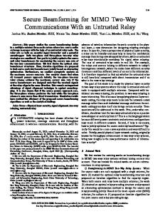
Fig. 1. MIMO two-way X relay channel.
where and denote the received signal vector and the additive white Gaussian noise (AWGN) vector at the relay, respectively; is the transmitted signal vector by source node with the power constraint is channel matrix from source node to the relay. the The entries of the channel matrices for, , and those of the noise vector , are independent and identically distributed (i.i.d.) zero-mean complex Gaussian random variables with unit variance, i.e., . Hence, all channel matrices are of full rank with probability 1. After receiving the signals from the source nodes, the relay forms a new signal and broadcasts it to all source nodes, which is known as the broadcast (BC) phase. The received signal at the th source node is given by (2) where and denote the received signal vector and is the AWGN vector at the th source node, respectively; the transmitted signal vector by the relay with the power constraint is the channel matrix from the relay to source node . Similar to the MAC phase, we assume that and contain i.i.d. random variables. Throughout this paper, it is assumed that perfect channel state information (CSI) is available at all source nodes and the relay. Additionally, we assume that the source nodes and the relay operate in full-duplex mode. We define the total DOF of the above MIMO two-way relay X channel as
II. MIMO TWO-WAY X RELAY CHANNEL Consider a MIMO two-way X relay channel shown in Fig. 1. The channel consists of four source nodes with antennas each and a relay with antennas. Each source node , for on the left-hand side (LHS) needs to send an independent message, denoted as to each source node , for on the right-hand side (RHS) via the relay. So does each source node on the RHS. The transmission is implemented in two phases. In the multiple-access (MAC) phase, all four source nodes transmit their signals to the relay. The received signal at the relay is given by (1)
(3) is the DOF from source node to source node , and is the sum rate as a function of SNR, where SNR is defined as since the noise samples are assumed to have unit variance.
where
III. AN UPPER BOUND ON DOF In this section, we derive an upper bound on the DOF of the MIMO two-way X relay channel. Theorem 1: Consider a MIMO two-way X relay channel with antennas at every source node and antennas at the relay.
XIANG et al.: DEGREES OF FREEDOM FOR MIMO TWO-WAY X RELAY CHANNEL
1713
interference. In this section, by applying signal alignment for network coding and joint transceiver design for interference cancellation, we propose a novel transmission scheme, named as “Signal Alignment with Joint Interference Cancellation (SAJIC)” for the MIMO two-way relay X channel to maximize its total DOF. A. A Motivating Example for As an example, we consider a system where each source node has antennas and the relay has antennas. For this system, the proposed transmission scheme achieves Fig. 2. One direction of network information flow for the MIMO two-way X relay channel.
The total number of DOF is upper bounded by i.e.,
, (4)
Proof: We first consider the network information flow of one direction, i.e., from source nodes 1, 2 to source nodes 3, 4 via the relay, as shown in Fig. 2. In the MAC phase (cut 1), source nodes 1, 2 simultaneously transmit information to the relay. Assuming source nodes 1 and 2 fully cooperate, the channel essentially becomes a MIMO channel, whose DOF is [24]. In the BC phase (cut 2), we can obtain the similar result. Applying the cut-set theorem [25] to each phase with regard to the DOF, we can have
. In particular, source node 1 transmits codewords for message by using beamforming vectors , respectively to source node 3 (source node 4) via the relay. Similarly for the other three source nodes. Step 1: Signal Alignment During the MAC Phase: During the MAC phase, there are totally 16 data streams arriving at the relay. Since the relay has only 8 antennas, it is impossible for it to decode all the 16 data streams. However, based on the idea of physical layer network coding, the relay node only needs to decode some mixtures of the symbols. Specifically the key point of the proposed scheme is to obtain the network coded messages and at the relay (Note that each message consists of two streams.). Inspired by the signal alignment for network coding [20], we design the beamformers so that the two desired signals for network coding are aligned within the same spatial dimension. Taking source node 1 as an example, we align its transmitted data streams with the streams from source node 3, 4 as follows
(5) For the other direction of the network information flow, we can similarly obtain (6) Combining (5), (6) and using the definition in (3), we conclude (4) which completes the proof. Remark 1: The factor 2 on the RHS of (4) is due to the assumption of full-duplex mode in our scheme. The same assumption is also used in [20]. If half-duplex mode is assumed, the factor of 2 is not needed. From the above result, we can see that when , the total DOF for the MIMO two-way X relay channel is upper bounded by twice the number of antennas at the relay, which is therefore the bottleneck for the spectrum efficiency of the network. In the remainder of the paper, we assume that so . Since the transmission that the upper bound on the DOF is scheme for the case of will be completely different from that for the case of , we will leave the case of to future work. IV. EFFICIENT TRANSMISSION SCHEME For relay-aided bidirectional channels, applying physical layer network coding at the relay can significantly improve the system’s spectrum efficiency; and for multiuser channels, beamforming is typically employed to nulled out the inter-user
(7) where are the signal vectors seen by the relay. Fig. 3 illustrates the notion of the signal alignment in the MAC phase where it is seen that there are 8 network coded symbols aligned along 8 signal vectors, respectively. With antennas, the relay can then obtain the above 8 network coded symbols. Step 2: Joint Transceiver Design for Interference Cancellation During the BC Phase: During the BC phase, the relay broadcasts these four network coded messages using beamformers . More specifiare for messages cally, , respectively. Note that at the receiver side each source node suffers from two sources of interference and each component of the transmitted signal causes interference to two source nodes. For instance, source node 1 suffers from the interference caused by ; and causes interference to source nodes 2, 4. Each source node employs a linear receiver, with the 4 5 receiving filter matrix denoted as , for . Denote the effective channel matrix from the relay to source node as . The goal of transmit beamformer design at the relay is to make each component of the transmitted
1714
IEEE TRANSACTIONS ON SIGNAL PROCESSING, VOL. 61, NO. 7, APRIL 1, 2013
Fig. 3. Signal alignment for network coding during the MAC phase.
signal to lie in the null space of the effective channel matrices of those unintended source nodes. For example, should satisfy the following condition
(8) Fig. 4. Joint interference cancellation during the BC phase.
B. Necessary Condition for is the receiving filter vector for source node where to extract the th data stream from source node . However, the dimension of the matrix on the RHS of (8) is 8 8 and in general it is full-rank if each source node chooses its receiving vectors independently. Therefore it is not possible to find that satisfies (8). In order to circumvent this problem, we consider joint transceiver design for the source nodes and the relay. More specifically, for source nodes 2, 4, we constrain their receiving vectors to satisfy
(9) That is, the effective channel matrices for the network coded message from the relay to source nodes 2 and 4 are aligned. Then we can choose the transmitting beamformers that satisfy
When
From the above subsection, we can see that the proposed scheme SAJIC achieves the DOF upper bound for . In this subsection, we analyze the condition to achieve the . DOF upper bound when In order to maximize the DOF, it is intuitive that the number of data streams between each pair of communicating source nodes should be the same, i.e., 1. Note that the DOF indicates the maximum number of independent data streams that can be simultaneously transmitted in the network. Based on the signal alignment, it can be seen that the dimension of the intersection space of the channels of each source node pairs determines the maximum number of data streams we can align. Taking source nodes 1, 3 as an example, according to the dimension theorem [26] and due to the linear independence of the channel matricies, we obtain that
(10) (11) which implies that which is feasible since the dimension of the concatenated effective channel matrices is degraded to 6 8. The other transmitting and receiving beamformers are designed similarly so that the interference streams are nulled out for each source node. Fig. 4 illustrates the process of joint transceiver design for interference cancellation between source nodes and the relay in the BC phase.
(12) 1If there is one pair of source nodes which send different number of data streams, the source node with fewer data streams can send extra data streams without increasing the signal space to align with the extra data streams transmitted by the other source node.
XIANG et al.: DEGREES OF FREEDOM FOR MIMO TWO-WAY X RELAY CHANNEL
For the other pairs of communicating source nodes, we similarly have
1715
where are transmitting vectors seen by the relay. The above conditions imply that
(13) Combining (12)–(13), we have (14) In order to achieve the upper bound, we must satisfy the following condition (15) Based on (14) and (15), we obtain
which is equivalent to
(19) Since all the entries of the channel matrices are i.i.d. zeromean complex Gaussian random variables, there exists a -dimensional intersection subspace constituted by the column space of channel matrices for each pair of communicating source nodes with probability 1. Then we can always choose linearly independent transmitting vectors for each source node pair. As a result, the received signal in (1) is rewritten as follows (20)
(16) Thus, we have obtained the necessary condition to achieve the for the MIMO two-way X DOF upper bound when relay channel. V. ACHIEVABILITY OF THE UPPER BOUND In this section, we generalize SAJIC in Section IV.A. to arbitrary with , and show that it achieves the DOF upper bound when . Therefore the necessary condition in Section IV.B to achieve the DOF upper bound is also sufficient. We first provide the transmission scheme for the case of and show that is achieved by this scheme. During the MAC phase, the th source node sends message to the th source node using independently encoded streams along beamforming vectors instance, the transmitted signal from source node 1 is
. For
where the vector
matrix
, and the
. Also since the entries of all channel matrices are independently Gaussian, the probability that a basis vector in the intersection space of one pair of source nodes’ channel matrices lies in the intersection space of another pair is zero. Thus is full-rank with probability 1, which guarantees the decodability at the relay. The four network coded messages of and are then obtained by applying the mapping principle of physical layer network coding [2] to each entry of . For the BC phase, the relay broadcasts the network coded and to all source nodes using messages encoded symbols along the beamforming vectors . More specifically, and are the encoded symbol vectors for and , respectively. Then the transmitted signal at the relay in (2) is rewritten as
(17) (21) and are the encoded symbol vectors where for and , respectively. The transmitted signals from other source nodes are in a similar form. In order for the relay to obtain the network coded messages and , we should carefully choose the beamforming vectors to satisfy the following signal alignment conditions
(18)
The received signal at source node 1 is given by
Recall that the matrices and are defined in Section IV.A. The first term in the bracket represents the comand , bination of the desired network-coded messages while the remaining two terms are the unwanted interference
1716
IEEE TRANSACTIONS ON SIGNAL PROCESSING, VOL. 61, NO. 7, APRIL 1, 2013
and . The received signals at the other source nodes are written in a similar way. Next, we jointly design the transceivers for the source nodes and the relay for interference cancellation. Due to the symmetry of the MAC and BC phases, we can design the receiving matrix on each source node such that the effective receiving channels of each source node pair are aligned:
Since the matrix at the end of (24) is full-rank, the dimension of its null space is always zero. For the other pair of source nodes, the same argument holds and the lemma follows. According to Lemma 1, it can be seen that all the beamat the relay are linearly independent with forming vectors probability 1. Thus the received signals at source node 1 can be rewritten as (25)
(22) Here, is a effective channel vector between source node and source node on the -th data stream. Since the signal alignment has been applied successfully in the MAC phase, for the BC phase, each source node can also choose its receiving vectors to satisfy the above conditions, and the resulting effective channel vectors are linearly independent with probability 1. For the beamforming vectors at the relay, we can choose them to lie in the intersection subspace of each source node pair’s effective channels’ null space as follows
Thus, there is no interference for source node 1 and it can decode these useful signals. Then by using its own messages, source node 1 can obtain the messages from source nodes 3, 4 as follows (26) In the same manner, the other source nodes can also obtain the messages intended for themselves. Therefore, a total of DOF is achieved by using the proposed scheme on MIMO two-way X relay channel. A.
or
For the other cases that or choose the DOF for each pair for different values of
, we can as below
(23) We show that there exists a -dimensional null space for the concatenated effective channel matrix of each pair of communicating source nodes with probability 1. Taking source nodes 2 and 4 as an example, the dimension of is . Since we have aligned their receiving effective channels in (22), has repeated rows and its rank is . Therefore, the dimension of its null space is . For the other source node pairs, we can similarly get the result. Lemma 1: During the BC phase, the null space of the concatenated effective channel matrix for each source node pair has no intersection with that of the other source node pairs, i.e.,
Proof: We first consider the concatenated effective channel matrices for source node pairs (1, 3) and (1, 4), and have that We can similarly apply the previous transmission scheme to achieve the upper DOF bound and the process is briefly described as follows. For the MAC phase, we show that the signals for each pair of source nodes can be aligned at the relay: since (24)
XIANG et al.: DEGREES OF FREEDOM FOR MIMO TWO-WAY X RELAY CHANNEL
we can have (27) For the BC phase, the receiving alignment is also feasible just as for the MAC phase. For the transmitting beamforming design at the relay, we show that relay can always choose linearly independent beamforming vectors for each part of the sigas an nals. Without loss of generality, we take example, which should satisfy the following condition (28) Since .. .
.. . (29)
.. .
.. .
we have
1717
we have shown that this condition is also sufficient. Hence we have the following main result of this paper. , the necessary and sufficient Theorem 2: When condition for SAJIC to achieve the DOF upper bound in the MIMO two-way X relay channel is . , the DOF upper bound can Remark 3: When also be achieved by applying standard techniques in two-way relay channel. More specifically, we only allow one source node pair to use the relay in one time slot and apply time sharing among different source node pairs. In each time slot, the network just reduces to the standard two-way relay channel and those existing techniques can then be used. It can be seen that this simple method can achieve . However, it can no longer achieve the DOF upper bound when . is Next, we analyze the achievable DOF when not satisfied. When , although our proposed scheme SAJIC cannot achieve the DOF upper bound , it can still work. More specifically, the dimension of intersection space for each source node pair’s channel matrices is . Following the outline in previous sections, it can be seen that the total DOF SAJIC can achieve is . Compared with the DOF upper bound, the gap is . When , SAJIC is not feasible since the dimension of intersection space for each source node pair’s channel matrices is zero. VI. CONNECTION WITH THE TRANSMISSION METHOD IN [23]
(30) Finally, we summarize the algorithm for SAJIC in the following chart. Outline of SAJIC: • Step 1. In the MAC phase, each source node designs its beamforming vectors according to (18) so that the two desired signals for network coding are aligned at the relay node. • Step 2. By applying the mapping principle of physical layer network coding, the relay then decodes its received signals to obtain the network coded messages . • Step 3. In the BC phase, the source nodes and the relay jointly design their transceivers. More specifically, all the source nodes design their receiving filter matrices according to (22); the relay designs its transmitting beamforming vectors according to (23) to cancel the interference for each source node. • Step 4. Each source node decodes its received signals to obtain the network coded messages intended for itself. Using its side-information, each node finally acquires its desired messages . Remark 2: We can see that the DOF for each source node may not be the same when is not a multiple of 4. However, we can apply four time slots extension here to let every source node achieve the same DOF . Specifically, when using time extension of 4 channel uses, the channel is equivalent to a MIMO two-way X relay channel in which each source node has antennas and the relay has antennas. Then our proposed scheme SAJIC can be applied to this situation directly and each node achieves the equal DOF of . In Section IV.B we have shown that is a necessary condition to achieve the DOF upper bound. And in this section
In the previous sections, we have shown that using our SAJIC, the cut-set outer bound for the DOF can be achieved when . Specifically, we align the signals for each pair of source nodes in the MAC phase and apply joint transceiver design for interference cancellation in the BC phase. In this section, we will show that if we do not consider the joint transceiver design but directly apply interference nulling beamforming at the relay in the BC phase, our proposed scheme will reduce to a generalized version of the transmission method in [23]. For the reduced or simplified transmission scheme which does not apply the joint transceiver design in the BC phase, we consider as an example the case . In the MAC phase, we similarly apply signal alignment as in (18). In the BC phase, since we directly apply interference nulling at the relay, the relay will cancel one part of interference for each source node, leaving the remaining part of interference to be cancelled by the source node itself. More specifically, the relay can choose its beamformers as
(31) For each channel matrix , there exists a -dimensional null space with probability 1. Then for each network coded message, the relay can choose linearly independent vectors. Also it can be easily seen
1718
IEEE TRANSACTIONS ON SIGNAL PROCESSING, VOL. 61, NO. 7, APRIL 1, 2013
that the beamforming vectors are linearly independent with probability 1. Thus the received signals at source node 1 can be rewritten as
cancel by itself is . Then the interference dimension that needs to be nulled at the relay is
(32)
antennas and the dimenNote that source node 1 has sion of the useful signal is . So it has exactly free dimensions for the interference signal whose dimension is also . Thus source node 1 can cancel the other part of the interference by itself. More specifically, source node 1 can choose as follows its receiving matrix
(33) Since is an matrix, the dimension of its left null space is . Source node 1 can choose linearly independent receiving filter row vectors, and is full-rank with probability 1. Then the received sighence nals for source node 1 is (34)
There is no interference and source node 1 achieves the DOF of . The other source nodes operate in the same manner. Therefore, the reduced transmission scheme also achieves the total DOF of . Remark 4: The method given in [23] corresponds to the reduced transmission scheme for . Next, we show that the reduced transmission scheme requires a stricter condition to achieve the DOF upper bound, i.e., . In the MAC phase, the condition that the reduced scheme needs to satisfy is (35) which is the same as the original proposed transmission scheme. Extra conditions are needed in the BC phase for the reduced scheme. Lemma 2: For the reduced transmission scheme in the BC phase, for each source node, the dimension of the interference that needs to be canceled by the relay is2 . Proof: Without loss of generality, we take source node 1 as an example. For source node 1, the dimension of useful signals is ; while the dimension of interference is . Since it has antennas, the interference dimension that it can 2If , the relay does not need to cancel the interference and each source node can null all the interference it suffers by itself.
For the other source nodes, we can similarly obtain the result and the lemma follows. For source node 1, suppose out of interference streams and out of interference streams are nulled out at the relay. Then according to Lemma 2, we have (36) is also , the Since the dimension of the null space of relay can choose beamformers which lie in its channel matrix’s null space to cancel these interference streams. For source node 2, we can similarly have that (37) We now consider source node 3 and source node 4. As for source node 3, the interference signals consist of data streams. From the previous discussion, we know that out of data streams lie in the null space of source node 2’s channel matrix; and out of data streams lie in the null space of source node 1’s channel matrix. These interference signals cannot lie in the null space of and therefore cannot be nulled out by the relay: the proof technique is similar to that applied in Lemma 1. Thus, source node 3 must cancel them by itself, which implies that (38) Similarly for source node 4, we should have (39) Combining (38) and (39), we have (40) Plugging (15), (36) and (37) into (40), we then obtain (41) which is the condition the reduced scheme should satisfy in the BC phase. Now combining (35) and (41), the necessary condition for the reduced scheme to achieve the upper bound becomes simply (41). From the above analysis, it can be seen that using the reduced transmission scheme, we can achieve the DOF upper bound in a range . By further applying joint transceiver design for interference cancellation in the BC phase, our proposed scheme can achieve the upper bound in a wider range .
XIANG et al.: DEGREES OF FREEDOM FOR MIMO TWO-WAY X RELAY CHANNEL
1719
In the BC phase, the achievable rate for and 3 is given by
at source node 1
Then we have (42)
Fig. 5. The ergodic sum rate for the MIMO two-way X relay channel under different network architectures.
The rates of other pairs of communicating source nodes can be computed in a similar way. Thus, we can obtain the achievable sum rate for the whole network when SAJIC is applied. In Fig. 5, we plot the sum rate performance of the proposed scheme according to various antenna configurations. We can see that, as analyzed in Section V, the proposed scheme indeed achieves the upper bound on the DOF. Specifically, we can always observe a sum-rate increase of bps/Hz for every 3 dB increase in SNR. For instance, when , the curve has a slope of . In Fig. 6, we plot the sum rate performance of the network when the number of antennas at each source is fixed. It can be seen that as the number of antennas at the relay increases, the total DOF also increase, which shows that the relay antenna number is a bottleneck of the network when . VIII. CONCLUSION
Fig. 6. The ergodic sum rate for the MIMO two-way X relay channel when is fixed.
VII. SIMULATION RESULTS In this section, we provide numerical results to show the ergodic sum rate performance for the proposed transmission scheme. Then, we will demonstrate that the proposed scheme exactly attains the upper bound on the DOF derived in Section V. The channel is assumed as the normalized Rayleigh fading channel, i.e., the elements of each channel vector are independent and identically distributed circularly symmetric zero-mean complex Gaussian random variables with unit variance. The numerical results are illustrated with respect to the ratio of the total transmitted signal power to the noise variance at each receive antenna in decibels . Each result is averaged over 10000 independent channel realizations. We now explain how we compute the sum rate for the MIMO two-way X relay channel when applying the SAJIC. In the MAC phase, assuming that the zero forcing detector is applied by the relay, the achievable rate for network coded message is calculated as
This paper considered the total DOF for the MIMO two-way X relay channel. We analyzed the upper bound on the DOF for such a network. Then by exploiting physical layer network coding and joint interference cancellation, we proposed SAJIC and showed that SAJIC can achieve the upper bound if and only if . Also, we generalized the scheme in [23] and derived a necessary condition for it to achieve the upper bound. Besides, we analyzed the relationship between these two schemes and showed that our proposed SAJIC can be reduced to the generalized version of the scheme in [23] after some simplification. The achievability of the upper bound on the DOF for the considered network in the case of and the case of remains open for further investigation. REFERENCES [1] R. Ahlswede, N. Cai, S. Li, and R. Yeung, “Network information flow,” IEEE Trans. Inf. Theory, vol. 46, no. 4, pp. 1204–1216, Jul. 2000. [2] S. Zhang, S. Liew, and P. Lam, “Physical-layer network coding,” in Proc. ACM MobiCom, New York, NY, USA, Sep. 2006, pp. 358–365. [3] S. Katti, S. Gollakota, and D. Katabi, “Embracing wireless interference: Analog network coding,” in Proc. ACM SIGCOMM, New York, NY, USA, Sep. 2007, pp. 397–408. [4] R. Wang and M. Tao, “Linear precoding designs for amplify-and-forward multiuser two-way relay systems,” presented at the IEEE GLOBECOM, Houston, TX, USA, Dec. 5–9, 2011. [5] J. Joung and A. Sayed, “Multiuser two-way amplify-and-forward relay processing and power control methods for beamforming systems,” IEEE Trans. Signal Process., vol. 58, no. 3, pp. 1833–1846, Mar. 2010. [6] C. Wang, H. Chen, Q. Yin, A. Feng, and A. Molisch, “Multi-user two-way relay networks with distributed beamforming,” IEEE Trans. Wireless Commun., vol. 10, no. 10, pp. 3460–3471, Oct. 2011. [7] M. Tao and R. Wang, “Linear precoding for multi-pair two-way MIMO relay systems with max-min fairness,” IEEE Trans. Signal Process., vol. 60, no. 10, pp. 5361–5370, Oct. 2012.
1720
IEEE TRANSACTIONS ON SIGNAL PROCESSING, VOL. 61, NO. 7, APRIL 1, 2013
[8] E. Yilmaz, R. Zakhour, D. Gesbert, and R. Knopp, “Multi-pair two-way relay channel with multiple antenna relay station,” presented at the IEEE ICC, Cape Town, South Africa, May 23–27, 2010. [9] T. Koike-Akino, M. Pun, and P. Orlik, “Network-coded interference alignment in k-pair bidirectional relaying channels,” presented at the IEEE ICC, Kyoto, Japan, Jun. 5–9, 2011. [10] D. Gunduz, A. Yener, A. Goldsmith, and H. Poor, “The multi-way relay channel,” presented at the IEEE ISIT, Seoul, Korea, Jun. 28–Jul. 03, 2009. [11] L. Ong, S. Johnson, and C. Kellett, “An optimal coding strategy for the binary multi-way relay channel,” IEEE Commun. Lett., vol. 14, no. 4, pp. 330–332, Apr. 2010. [12] Z. Zhou, K. Teav, and B. Vucetic, “Beamforming optimization and power allocation for MIMO asymmetric multi-way relay channels,” IEEE Commun. Lett., vol. 16, no. 6, pp. 820–823, Jun. 2012. [13] S. Jafar and S. Shamai, “Degrees of freedom region of the MIMO X channel,” IEEE Trans. Inf. Theory, vol. 54, no. 1, pp. 151–170, Jan. 2008. [14] M. Maddah-Ali, A. Motahari, and A. Khandani, “Communication over MIMO X channels: Interference alignment, decomposition, and performance analysis,” IEEE Trans. Inf. Theory, vol. 54, no. 8, pp. 3457–3470, Aug. 2008. [15] V. Cadambe and S. Jafar, “Interference alignment and degrees of freedom of the k-user interference channel,” IEEE Trans. Inf. Theory, vol. 54, no. 8, pp. 3425–3441, Aug. 2008. [16] K. Gomadam, V. Cadambe, and S. Jafar, “A distributed numerical approach to interference alignment and applications to wireless interference networks,” IEEE Trans. Inf. Theory, vol. 57, no. 6, pp. 3309–3322, Jun. 2011. [17] S. Jafar, “The ergodic capacity of phase-fading interference networks,” IEEE Trans. Inf. Theory, vol. 57, no. 12, pp. 7685–7694, Dec. 2011. [18] T. Gou, C. Wang, and S. Jafar, “Aiming perfectly in the dark-blind interference alignment through staggered antenna switching,” IEEE Trans. Signal Process., vol. 59, no. 6, pp. 2734–2744, June 2011. [19] S. Jafar, “Interference alignment: A new look at signal dimensions in a communication network,” Found. and Trends in Commun. and Inf. Theory, vol. 7, no. 1, pp. 1–136, 2011 [Online]. Available: http://dx. doi.org/10.1561/010000047 [20] N. Lee, J. Lim, and J. Chun, “Degrees of freedom of the MIMO Y channel: Signal space alignment for network coding,” IEEE Trans. Inf. Theory, vol. 56, no. 7, pp. 3332–3342, Jul. 2010. [21] K. Lee, N. Lee, and I. Lee, “Achievable degrees of freedom on k-user Y channels,” IEEE Trans. Wireless Commun., vol. 11, no. 3, pp. 1210–1219, Mar. 2012. [22] N. Wang, Z. Ding, X. Dai, and A. Vasilakos, “On generalized MIMO y channels: Precoding design, mapping, and diversity gain,” IEEE Trans. Veh. Technol., vol. 60, no. 7, pp. 3525–3532, Sep. 2011. [23] K. Lee, S. Park, J. Kim, and I. Lee, “Degrees of freedom on MIMO multi-link two-way relay channels,” presented at the IEEE GLOBECOM, Miami, FL, USA, Dec. 6–10, 2010. [24] L. Zheng and D. Tse, “Diversity and multiplexing: A fundamental tradeoff in multiple-antenna channels,” IEEE Trans. Inf. Theory, vol. 49, no. 5, pp. 1073–1096, May 2003. [25] T. Cover and A. Gamal, “Capacity theorems for the relay channel,” IEEE Trans. Inf. Theory, vol. 25, no. 5, pp. 572–584, Sep. 1979. [26] G. Strang, Linear Algebra and Its Applications, International ed. Pacific Grove, CA, USA: Brooks/Cole, 2004.
Zhengzheng Xiang received the B.S. degree in electronic engineering from Shanghai Jiao Tong University, Shanghai, China, in 2010. He is currently working toward the Ph.D. degree with the Institute of Wireless Communication Technology, Shanghai Jiao Tong University. His research interests include interference management in wireless networks, wireless relay technologies, and advanced signal processing for wireless cooperative communication.
Meixia Tao (S’00–M’04–SM’10) received the B.S. degree in electronic engineering from Fudan University, Shanghai, China, in 1999, and the Ph.D. degree in electrical and electronic engineering from Hong Kong University of Science and Technology in 2003. Formerly, she was a Member of Professional Staff at Hong Kong Applied Science and Technology Research Institute during 2003–2004, and a Teaching Fellow then an Assistant Professor at the Department of Electrical and Computer Engineering, National University of Singapore, from 2004 to 2007. She is currently a Professor with the Department of Electronic Engineering, Shanghai Jiao Tong University, China. Her current research interests include physical layer network coding, wireless resource allocation, MIMO techniques, and physical layer security. Dr. Tao is an Editor for the IEEE TRANSACTIONS ON COMMUNICATIONS and the IEEE WIRELESS COMMUNICATIONS LETTERS. She was on the Editorial Board of the IEEE TRANSACTIONS ON WIRELESS COMMUNICATIONS from 2007 to 2011 and the IEEE COMMUNICATIONS LETTERS from 2009 to 2012. She also served as Guest Editor for IEEE Communications Magazine with feature topic on LTE-Advanced and 4G Wireless Communications in 2012, and Guest Editor for EURISAP Journal on Wireless Communications and Networking with Special Issue on Physical Layer Network Coding for Wireless Cooperative Networks in 2010. She is the recipient of the IEEE ComSoC Asia-Pacific Outstanding Young Researcher Award in 2009 and the corecipient of the International Conference on Wireless Communications and Signal Processing (WCSP) Best Paper Award in 2012.
Jianhua Mo received the B.S. degree in electronic engineering in Shanghai Jiao Tong University, China, in 2010. He is currently working towards dual M.S. degrees from Shanghai Jiao Tong University and the Georgia Institute of Technology, Atlanta, GA, USA. His research interest is physical layer security.
Xiaodong Wang (S’98–M’98–SM’04–F’08) received the Ph.D. degree in electrical engineering from Princeton University, Princeton, NJ, USA. He is a Professor of Electrical Engineering at Columbia University, New York, NY, USA. His research interests fall in the general areas of computing, signal processing, and communications, and he has published extensively in these areas. Among his publications is a book entitled Wireless Communication Systems: Advanced Techniques for Signal Reception (Prentice-Hall, 2003). His current research interests include wireless communications, statistical signal processing, and genomic signal processing. Dr. Wang received the 1999 NSF CAREER Award, the 2001 IEEE Communications Society and Information Theory Society Joint Paper Award, and the 2011 IEEE Communication Society Award for Outstanding Paper on New Communication Topics. He has served as an Associate Editor for the IEEE TRANSACTIONS ON COMMUNICATIONS, the IEEE TRANSACTIONS ON WIRELESS COMMUNICATIONS, the IEEE TRANSACTIONS ON SIGNAL PROCESSING, and the IEEE TRANSACTIONS ON INFORMATION THEORY. He is listed as an ISI HighlyCited Author.