CREATION OF REGULAR SYSTEM OF MW DISCHARGES WITH ELECTROMAGNETIC VIBRATOR LOCATED CLOSE TO A METAL SURFACE A.A. Ravaev, I.I. Esakov, P.B. Lavrov FSUE “Moscow Radiotechnical Institute RAS”, Moscow, Russia,
[email protected]
of localized microwave (MW) discharges formed in the field of a quasioptical electromagnetic beam of the remote source of MW energy has been offered [1,2]
Abstract In the present report various systems of new type initiators in the form of an array of linear “half-wave” pieces of a metal wire located in parallel to flow in vicinity of a metal screen-reflector are considered. The main advantage of such new type initiators is possibility to generate discharges in very low microwave fields (< 100V/sm) or using low-power MW radiation sources. In addition, solution of well-known problem of excitation of a multi-mode structure of electromagnetic waves in the multi-vibrator system is significantly simplified. Herewith, energy release in space becomes homogeneous. One of the considered designs also allows simulating conditions of electrodeless supply of electromagnetic energy to the multi-system of initiators from “inside” of aerodynamic model. The results of 3D numerical simulation and experimental investigations of such regular multi-systems of initiators of MW discharges and characteristics of plasma formations on a body surface in air-flow are presented in this report. Influence of various parameters of a single initiator as well as an array of initiators (including their conductivity, design and dimensions) on their properties and efficiency of their work are considered in detail.
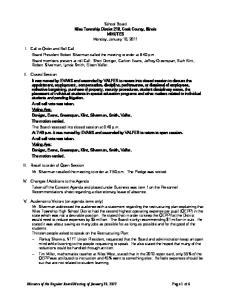
First of all, available experience of creation of so-called deeply subcritical microwave discharges (which are not exist without application of special initiators, attached after creation to the initiator end or gap and can produced in very low microwave fields) in experiments in stationary air and in high-speed air flows has been analyzed. Mainly, this experience concerns applications of various-type EM vibrators as an initiator. On the basis of this analysis, initially three types of initiators have been selected for the future investigations: (a) the linear EM vibrator, (b) the linear EM vibrator with a central gap, and (c) the magnetic loopback EM vibrator with a gap, see Fig.1. The theory and methods of calculation of such initiators are stated in work [3].
y
MW-discharged region
Hz Ex a)
1. Introduction
b)
с)
Air-Flow
Fig.1. Three types of intiators
Research and development of plasma methods of control of aerodynamic factors and boundary-layer characteristics is of great scientific and applied interest. Thus, for example, an energetically effective control method based on generation on a streamline body surface of a regular system
The linear EM vibrator is the most studied in our experimental and theoretical investigations type of MW-discharged plasma initiators. Its properties are already well-known and its advantages are: simple 1
design, well studied dependences of a field near the ends on various factors, and capability to produce breakdown at very high levels of sub-criticality of an initial MW field. Of course, in the present experiments the discharge at atmospheric pressure is also easily ignited by such an initiator. Typical view of deeply subcritical MW discharge at atmospheric pressure in stationary air is shown in Fig.2.
η
Etop E0
,
(1)
where Etop is maximum field at vibrators’ ends or in their electrode gaps, E0 – field amplitude of an incident MW radiation in place of vibrator location without it. The factor depends on full length of the vibrator 2L. The second type of investigated initiators is the linear EM vibrator with a central electric gap. It was supposed that the field in the gap between vibrator shoulders may be much higher as compared with fields at the ends of usual linear EM vibrator. Really, one can easily realize the MW discharge with such initiator at atmospheric pressure. Typical view of the MW discharge in the central gap of the linear EM vibrator is shown in Fig. 4.
Fig.2. MW discharge produced by linear EM vibrator If length of vibrator is comparable with half wavelength of MW radiation, it possesses strongly pronounced resonance characteristics. The vibrator placed in the MW field with linear polarization in parallel to electric field, provides maxima of the induced field on its both ends (Fig. 3).
Fig.4. MW discharge initiated by linear EM vibrator with the central gap
Fig.5. Amplitude distribution of an electric field along linear EM vibrator with a gap
Fig.3. Amplitude distribution of an electric field of the linear passive electomagnetic vibrator
The third type of the initiator which has been experimentally investigated is the magnetic-type loop-back vibrator with a gap. In first experiments such various vibrators with different configuration have been tested: ring, rectangular, etc. In all cases it was possible to initiate deeply
One of the main parameters of an initiator, characterizing its ability to ignite MW discharge, is the coefficient of electric field increase:
2
subcritical MW discharge. The external view of discharges initiated by the loop with the ring shape is shown in Fig. 6.
impossible to create required regular system of MW-plasma formations on airfoil model surface. Therefore further we passed to studying of other type of the initiator of the microwave discharges.
Fig. 6. MW discharge in the gap of loopback EM vibrator of the ring form
Fig.8. Airfoil model and periodic system of multiple MW discharges on its surface
Fig.8. Amplitude distribution of an electric field in Lope-shape passive vibrator Experience obtained working on the project, carried out cycle of experimental and theoretical investigations have allowed to develop and successfully test full-size airfoil model with 19 plasma initiators with spatial step λz = 10 mm over full span of the model [4]. External appearance of model and corresponding system of MW discharges at executing those tests in the wind-tunnel chamber are presented in Fig.8. During aerodynamic experiments it was found out that it is necessary to create system of initiators with smaller spacing λz. Numerical simulation of the system of ring initiators with parameter λz = 5 mm has been executed. The result has demonstrated that there is a multimode wave structure in such system, and MW field at tips of some initiators will be less than breakdown threshold, see Fig. 9. In other words, because of strong interaction of such closelocated EM vibrators in system it was
Fig.9. Amplitude distribution of an electric field in system lope-shape passive vibrators 3
Besides, Fig.11 illustrates the following result of calculations. The induced fields are maximal near to the end surfaces of the vibrator. At comparatively high values h they their distribution is almost symmetrical relative to the vibrator axis. But at its displacement toward the metallic screen this field starts to concentrate between the polar surfaces of the vibrator turned to the screen and the screen. Thus “points” of maximum Epol located on a surface of the vibrator are displaced from its axis toward the screen. This is well shown as it looks in actual experiment in Fig. 12. So one can also conclude that influence of the considered initiator on neighbor initiators at h << λ is significantly less than if any screen is absent.
2. MW-discharge initiators located close to a metal screen-reflector The further search of ways of increase of an overall performance of initiators of MW discharges in the field of a quasioptical microwave beam has led to development of essentially new type of the linear electromagnetic vibrator located in direct vicinity of the conducting screen-reflector. Influence of various parameters of such a single initiator and of an array consisting of a number of similar initiators, including their conductivity, geometrical sizes and shape, on local properties of induced electromagnetic fields, quality factor and frequency characteristics was considered in detail in previous works [4]. In particular it was demonstrated that in absence of dielectric material between an initiator and metallic reflector (or in the case when loss tangent of a dielectric material is equal zero and conductivity of vibrator ζ = ∞) the dependence of the amplification coefficient of electric field strength at the vibrator tip vs. distance between the vibrator and metallic foil η(h) has monotonic and expressed exponential character, and at h → 0 η → ∞. In Fig. 10 one can see the graph of dependence of the coefficient of electric field increase at the end of the initiator η(h). The continuous line corresponds to calculated values max(h) and the dashed line represents experimental data.
h=31mm
h=3mm
Fig.11. Typical examples of calculated field distributions of the induced field in vicinity of EM vibrator; at the left h = 31 mm, and on the right h = 3 mm
1200 max 1000 800 600 400 200 0 0
Fig.12. Typical examples of localization of MW-discharged plasma formations initiated by EM vibrator in the field of quasioptical microwave beam; a – 31 mm, b – 3 mm.
h, mm 10 20 30 40 50 60
Fig.10. Dependence of the coefficient of electric field increase at the initiator end on the distance h 4
permittivity ε = 5.5 and microwave loss tangent tgδ ≈ 0.04) is of great interest. In the numerical model, the EM vibrator represents a rectilinear piece of wire with a varied length 2L and the fixed diameter 2a = 0.35 mm “made” of Ni-Cr alloy with conductivity ζ = 1·106 S/m. The vibrator is completely immersed into the dielectric substrate; its axis is at a distance h from the substrate foil. The MW electric probe is located at one of the vibrator ends. The resonant curve of the vibrator at distance h = 1.9 mm is shown in Fig.14. In comparison with similar vibrators without dielectric the quality factor and coefficient of amplification η of MW field of the considered design at very small distances h are comparatively small, and factor η ≈ 200 is obviously insufficient for reliable initiation of the multiple MW discharges in conditions of experiments using low-power MW generators. At the same time the resonant length of this vibrator 2L0 ≈ 28.7 mm that corresponds to angle of sector of the model’s cylinder φ < 300. As one would expect degree of shortening of geometrical length of the vibrator is approximately proportional ε1/2.
3. Linear electromagnetic vibrators on foil-laminated dielectric substrate According to experimental conditions the initiators should be mounted flush with aerodynamic body, therefore the following scheme of realization of such design have been suggested and tested, see Fig. 13. Here the initiator is a piece of some thin conducting wire or a metal strip located just on a surface of foil-laminated dielectric substrate. Its orientation is simultaneously parallel to the vectors of air flow velocity and of electric field E. However, a physical picture of excitation of electromagnetic field in vicinity of the electromagnetic vibrator located on a dielectric substrate possessing dielectric losses is much more complicated. Monotonic character of the function η(h) is already broken.
Microwave beam Strip initiator
Flow
Plasma
250
Dielectric
Coefficient of amplification
230
Foil
Fig.13. Designs of new-type electromagnetic vibrators on foil-laminated dielectric substrate. Results of 3D numerical simulation
210 190 170 150 130 110 90
Results of numerical simulation have confirmed the assumption that properties of a dielectric substrate in designs of considered here high-Q EM vibrators play the important role. Taking into account that fact that forthcoming experiments are supposed to be carry out with a cylindrical aerodynamic profile with rather small radius of curvature (2R = 90 … 120 mm), the degree of shortening of geometrical length of the linear half-wave vibrator at use of a real material (foil-laminated textolite with
70 27,5
28,0
28,5
29,0
29,5
30,0
30,5
Length 2L , mm
Fig.14. Resonant curve of the EM vibrator on foil-laminated textolite substrate at h = 1.9 mm One of the most important practical results is that because comparatively small curvature of the considered linear vibrator on the cylinder surface of radius R = 60 mm these vibrators will fully keep their unique properties being mounted on cylindrical 5
model with diameter 2R ≈ 100 mm. Only small correction of dimensions of a final design will be required. And at the first stage of further studying of properties of these MW-discharge initiators for reduction of computing and experimental time the use of a “flat” 3D vibrator model is justified. The curves presented in Fig.15 are even more indicative. Here influence of MW losses in real dielectrics on an efficiency of work of such initiators is clearly visible: in absence of losses but at terminal conductivity of a vibrator material (in our case of Ni-Cr alloy) the amplification factor maximum is displaced toward the reflector. Herewith their quality factor of an equivalent contour and coefficient η significantly increase. Note that in full absence of losses in system (loss tangent is equal zero and conductivity ζ = ∞) the function η(h) has monotonic and expressed exponential character, and at h → 0 η → ∞.
distribution of induced electromagnetic and resulting temperature fields on a model surface. Results of experimental investigations For qualitative checking of the above presented numerical results and conclusions a series of experiments has been executed. Available experimental Installation allows to carry out experiments with initiation of MW discharges at a lowered air pressure and high speeds of air flow in its working chamber. The following special devices were used in experiments: MW generator with irradiating system (pulsed and cwmode of operation, operating frequency – 2.45 GHz, output power – 1.5kW), the electromagnetic valve of gas (air) inlet, the Laval nozzle, and the vacuum chamber supplied with vacuum booster pumps and a special high-volume receiver. Key feature of described below experiments is that for determining of resonant characteristics of vibrators η = η (2L) the original techniques described in Ref. [5] was applied. The point is that the problem of measuring of a MW field in a vicinity of initiator of the MW discharge is very complicated task, especially considering the limited power dynamic range of available MW generators. The technique essence is that in the course of experiment instead of direct measurements of a MW field magnitude one measures pressure of gas breakdown. Unlike level of power of the MW generator, it is easier to vary in wide limits air pressure in the chamber. And there is the well-known direct dependence between pressure of breakdown and corresponding amplitude of electric field. The experimental scheme is depicted in Fig.16. Results of measurements of resonant characteristics of initiators are presented in Fig.17.
1000
Coefficient of amplification
900 800 700 600 500 400 300 200 100 0 0
5
10
15
Distance h , mm
Fig.15. Dependences of amplification factor on distance h for dielectric substrates with MW losses (green line) and without (rose line If by some reasons application of glassfiber laminate (textolite) with comparatively high MW losses is required the optimum thickness of a dielectric substrate in considered conditions increases to 7-8 mm. In this case the amplification factor η may be insufficient for reliable ignition of a multi-system of close-located discharges. Mutual influence of EM vibrators at higher distances h also increases. Last factor negatively affects on uniformity of 6
also its weight) and to improve performance of work both of a single MW-discharge initiator and of an array consisting of large number of such identical parallel initiators one should either choose materials with smaller values of loss tangent or to develop designs with incomplete filling of the intermediate space “vibrator-to-reflector” with a dielectric material. To summarize, the photos in Fig.18 illustrate the working ability and functionality of the multi-system of strip vibrators located on the dielectric substrate near to the metal screen-reflector in real experiment
Fig.16. Scheme of experiments 800 h = 4.8 mm
Breakdown pressure, Torr
700
h = 2.4 mm
600 500 400 300 200
a)
100 0 28
30
32
34
36
38
40
42
44
46
48
Length 2L , mm
Fig.17. Breakdown pressure vs. vibrator length at different thickness of dielectric substrate h Experimental and numerical results are found to be in a good agreement and are as follows: 1. The resonant length of the linear electromagnetic vibrator weakly depends on a thickness of the substrate h and decreases with h increasing; 2. Growth of h within a certain range results in widening of the resonant curve and an increased coefficient of amplification of E-field η(h) at the vibrator ends, see Fig.17. In other words, the optimum thickness of the foil-laminated dielectric substrate at the given wavelength of MW radiation of 12.24 cm is about several millimeters. The latter is a most important finding for further investigations. Obviously, in order to decrease a dielectric thickness (and
b)
c) Fig.18. External appearance of the working zone with strip multi-vibrator array (a); system of initiated MW discharges (b), and discharge tracing after irradiation (c) 7
4.New Γ-type electromagnetic vibrator as efficient initiator of microwave discharges The following type of the vibrator which was created during work is presented on fig. 19. High interest to new modification of this vibrator is caused by a number of prospective advantages. First, such design promises to be more technological and easy in adjustment as dielectric in this case plays only a role of the initiator holder and consequently it can consist of separate small moved parts. Last possibility can be used for fine adjustment of all vibrators in system. Secondly, exact trimming and polishing of all vibrators flush with a model surface is not required. Thirdly, in the given design it is possible to apply any materials including materials with low dielectric losses and, thereby, to vary quality factor Q and coefficient of amplification η of MW electric field induced on the ends of such vibrators. There is one more advantage of the given design, namely modeling of conditions of a noncontact (what is very important) supply of electromagnetic energy to initiator system from within aerodynamic model. Flow
Fig. 20. Gain factors of the EM vibrators
Metallic surface Plasma
Dielectric MW
Wire initiator
Рис. 19. Designs of new-type electromagnetic vibrators on airfoil model
Fig. 21. MW-field patterns in vicinity of the linear electromagnetic vibrator and near the gap of the ring-type magnetic vibrator
Results of 3D numerical simulation The result of numerical simulation is presented in fig. 20. It is visible that the gain factor of strengthening of a field on the vibrator end in this design can exceed 6000. It speaks about big efficiency of this type vibrator. Distribution amplitude of Electric field near the initiator is presented in fig. 21.
Results of experimental investigations At first three models with 4 initiators mounted on textolite of different thickness h have been manufactured, namely: h = 1 mm, 2 mm, and 3 mm (see Fig. 22). Diameter of apertures in the metal cover of model equaled 4 mm. In order to fasten initiators in the place where their ends leave on an external surface of model, special rapid8
hardening ceramics was applied. Other ends of vibrators were fastened with the foam holder. As earlier, the developed technique of measuring of breakdown air pressure pbr was applied to determine resonant characteristics of vibrators. Obtained dependences pbr (2L) presented in Fig. 23 allow to estimate with high accuracy main characteristics of EM vibrators, including their optimum distance from metal h and resonant length 2L.
а )
h. From the graphs one can see that an optimum thickness of the textolite holder is about h = 2 mm. Then the model consisting already of 10 vibrators has been calculated and manufactured. As the material of model in the area of MW discharges is heated up, first, the integral holder made of ceramics 2 mm in the thickness was used for fastening of initiators. In the given model distance between vibrators was of 10 mm, and diameter of a wire 1 mm. Appearance of the model and system of generated MW discharges on its bottom (opposite to MW irradiating antenna) surface are shown in Fig. 24.
b )
c
c Fig. 22. Experimental models with different thickness h of a textolite substrate: a) h = 1 mm, b) 2 mm, c) 3 mm
Fig. 24. External appearance of the vibrator design and system of generated MW discharges The ceramics has demonstrated good thermal stability, but in aerodynamic model where initiators should be mounted on a curvilinear surface (cylinder cover), its application is inconvenient. Therefore in all the following experiments textolite and
Fig. 23. Dependence of breakdown pressure on vibrator length at different thickness of dielectric substrate 9
rapid-hardening ceramics was used. Before aerodynamic experiment, preliminary tests of behavior of investigated microwave discharges in air flow with a speed of 15-20 m/s has been also executed. For this purpose the flat model with three initiators and distance between them about 15 mm has been prepared. Experiment has shown that in air flow the discharge does not drift and continues to burn steadily without any visible changes (Fig.25). And the developed design may be applied in joint aerodynamic experiments in the wind tunnel in IHM, Kiev.
The first variant such model, i.e. its working part consisting of a metal cylindrical segment and array of initiators has been developed. The radius of curvature of the first prototype of aerodynamic model equaled 120 mm; a step of an arrangement (spanwise spacing) of initiators was 7 and 10 mm. Diameter of Ni-Cr wire was 0.35 mm, and their distance over a metal cover h = 2 mm. External appearance of this model is shown in Fig.27.
Fig. 27. External view of the first prototype of cylindrical airfoil model, spanwise step of initiators λz = 10 mm After fine adjustment on the installation which is electrodynamic analogue of the working chamber of the wind-tunnel installation in IHM, Kiev, the demanded periodic system of microwave discharges on the external surface of the metal cover of model has been obtained, see Fig.28.
а b ) ) Fig. 25. Microwave discharges in airflow with speed V=0 m/s (a) and V=30 m/s (b) The following step is to bpass to the ) model with an arrangement of initiators on a curvilinear surface of aerodynamic model, i.e. on a cylindrical surface. This model design is depicted in Fig.26. In this case supply of MW energy is carried out from the top, and system of MW discharges is initiated on the bottom surface of model. MW
Fig. 28. Regular system of microwave discharges produced with design shown in Fig.27
Diel ect r iс par t of model shel l
9 0
I. Complete aerodynamic model as an assembly During preparation for aerodynamic experiments model with 18 initiators have been made. Model with 18 initiators have been used at carrying out of joint aerodynamic experiment. During tests some part of initiators has burnt out. Completely, before burning out all system of initiators has worked about 40 seconds. External view of cylindrical model
Text ol it e 0,, 0,2
Vibr at or
Met al l ic par t of model shel l Cer amics
Diel ect r ic hol der
Fig. 26. Scheme of arrangement of electromagnetic vibrators in the airfoil model 10
fig.29a, b and systems of initiated microwave discharges on the model surface at execution of tests in the wind-tunnel in IHM, Kiev, are presented below in Fig.29c.
electromagnetic vibrators as an integral part of model to initiate MW discharges. New efforts on perfection of system of initiators on model as an assembly should be continued. First of all one has to pay paramount attention to the joint, strictly coordinated approach as to a choice of a model design and materials of which it is made. Besides, at planning and execution of new similar projects in this prospective direction, taking into account strictly limited power of the used MW generator based on domestic magnetron and also remote external supply of MW energy one should change scheme of experiment and focus b further efforts on development of new ) feeding electrodynamic system with more efficient MW energy supply from inside of airfoil model.
а )
7. Summary Theoretical and experimental investigations of various initiators of MW discharges have been carried out. The main attention has been given to study of new high-Q linear electromagnetic Γ-shaped vibrator which is located near to the metallic screen-reflector. It is shown that this initiator possesses high values of multiplication factor of EM fields in its working gap not only alone but also as a part of a regular multi-system of such initiators on a model surface. It allows to apply again developed initiators in experiments with very small level of an initial electromagnetic field including use of the remote, far located source of MW radiation with limited microwave power. The developed type of the vibratorinitiator allows to carry out experiments with models with strongly curvilinear surface including cylindrical model with small radius of curvature, with a metal surface of its shell, and also to simulate conditions of MW energy supply to system of electromagnetic vibrators from interior of models. Properties of various type EM vibrators including the influence of MW losses of real
b
c Fig 26. External view of aerodynamic model and system of initiated microwave discharges. Carried out tests highlighted strong influence of some important constructive parts of the model and also of the working chamber as well as used materials on properties and long-term ability of 11
dielectric materials used in test models intended for aerodynamic experiments are studied in detail. Idea descried in the present report seems to be very productive. This-type EM vibrators can be successfully used as initiators of MW discharges in works on development of new method of boundarylayer control or creation of principally new MW ignition system in various engines, etc. The authors thank Dr. Tishkoff for attention to our work and fruitful discussions, and also Ukrainian colleagues Dr Yurchenko (IHM, Kiev) and Dr Vinogradsky (IHM, Kiev) for perennial collaboration, excellent organization and carrying out of joint aerodynamic experiments. The work is executed under financial support of European Office of Aerospace Research and Development, Project CRDF GAP # UKE2-1508A-KV-07 and CRDF GAP # UKE2-1518A-KV-07.
Khodataev, A. Ravaev, N. Yurchenko, P. Vynogradskyy, A. Zhdanov. Initiated surface microwave discharge as an efficient active boundary-layer control method. 47th AIAA Aerospace Sciences Meeting, 5-8 January 2009, Orlando, Florida, USA. Paper AIAA 2009-0889.
References 1. V.L. Bychkov, I. I. Esakov, L. P. Grachev, A. A. Ravaev, K. V. Khodataev, N. F. Yurchenko: Initiated surface MW discharge in experimental investigations of new boundary layer control method. // Proc. VI Intern. Symp. “Thermochemical Processes in Plasma Aerodynamics,” May 12-14, 2008, St-Petersburg. P. 27-29. 2. I.I. Esakov, L.G. Grachev L., Khodataev K., Ravaev A., Yurchenko N., Vinogradsky P., Zhdanov A. Initiated Surface Microwave Discharge as an Efficient Active Boundary-Layer Control Method. // Proc. 47th AIAA Aerospace Sciences Meeting and Exhibition, Jan 5-8, 2009, Orlando, Florida, USA. Paper: AIAA 2009-0889. 3. K.V. Khodataev . Various types of initiators for attached undercritical MW discharge ignition, 45th AIAA Aerospace Sciences Meeting, Reno, NV, USA, 2007, AIAA-2007-0431. 4. L. P. Grachev, I. I. Esakov, P. B. Lavrov, A. A. Ravaev. Technical Physics, 2012, 57, 230. 5. I. Esakov, L. Grachev, K. 12