SPIN WAVE PROPAGATION IN NON-UNIFORM MAGNETIC FIELDS
Michael J. Kabatek, Kevin R. Smith, Mingzhong Wu, and Carl E. Patton* Colorado State University, Department of Physics Fort Collins, Colorado, 80523
performed with a long and narrow magnetic yttrium iron garnet film strip. The non-uniform field was applied parallel to the long direction of the film strip, in the backward volume wave configuration. In this configuration, the frequency versus wave number dispersion relationship for low wave numbers has a negative slope and the group velocity for positive wave numbers is negative. The entire dispersion curve shifts up and down with the local magnetic field because of the Zeeman interaction. It is found that, in a non-uniform magnetic field, the wave number of the spin wave carrier changes while the carrier frequency remains constant. Specifically, the wave number increases in a spatially increasing field and decreases in a spatially decreasing field. Moreover, if the field changes back to its initial amplitude, the wave number also returns to its initial value. The shift in the local wave packet carrier wave number with field is a reversible process. In spite of these field dependent changes in the wave number, the group velocity of the spin wave pulses remains relatively constant for small changes in field.
ABSTRACT This paper reports high resolution time- and spaceresolved imagining of spin wave propagation in magnetic thin films under spatially non-uniform magnetic field configurations. The experiment was carried out with a yttrium iron garnet film strip magnetized with a spatially non-uniform magnetic field parallel to the length of the film strip. Spin wave pulses were excited with a microstrip transducer at one end of the strip. The propagation of spin wave pulses was mapped with a timeand space-resolved inductive magnetodynamic probe. The wave number of the carrier for the spin wave pulses were found to increase in a spatially increasing magnetic field and decrease in a spatially decreasing magnetic field. The wave number change for a general spatially varying static field is reversible.
1. INTRODUCTION At the most basic level, a spin wave excitation consists of the spatial propagation of the phase lead or lag for low amplitude spin precessions in a saturated ferromagnetic system (See Stancil, 1993; Kabos and Stalmachov, 1994). Previous research on spin wave excitations has generally focused on excitation and propagation in uniform magnetic fields. Most of the microwave devices developed over the last 50 years have also involved spin wave excitations in uniform magnetic fields. Examples of these devices include delay lines, phase shifters, and frequency selective limiters. The matter of spin wave propagation in non-uniform magnetic fields largely represents an open question. The basic propagation properties of spin wave excitations in spatially non-uniform magnetic fields are of fundamental and practical importance. A basic understanding of the properties of spin wave pulses in non-uniform fields can open up new radar and microwave signal processing device possibilities, among others.
2. EXPERIMENT Figure 1 shows a schematic of the experimental setup. The magnetic medium was a yttrium iron garnet (YIG) film strip cut from a larger single crystal YIG film grown on a gadolinium gallium garnet substrate by standard liquid phase epitaxy technique. The YIG strip was magnetized to saturation by a static magnetic field H ( z ) parallel to the length of the film strip. This film/field configuration supports the propagation of backward volume spin waves (See Stancil, 1993). The magnetic field was provided by an electromagnet. Different non-uniform field configurations were realized through the adjustment of the positions of magnet N-S pole pieces relative to the film/transducer structure. A microstrip line transducer was positioned over and at one end of the film strip to excite the spin wave pulses. The spin wave pulses propagating along the film strip were detected with a time- and space-resolved inductive magnetodynamic probe (See Wu et al., 2004). The detected signals were measured with a broadband real time microwave oscilloscope. The spatial scanning of the
This paper reports on recent time- and space-resolved measurements of spin wave pulse propagation properties in a magnetic film strip magnetized to saturation with non-uniform magnetic fields. The experiment was
1
x
Input
1.30
Output Computer
Increasing
z y
Magnetic field H (kOe)
Scanning stages x,y,z YIG film
Probe
N
S Microstrip transducer
H(z)
1.29 1.28 Sagging 1.27 Decreasing
1.26 1.25
Fig. 1. Schematic of experiment set-up. The yttrium iron garnet (YIG) film strip is magnetized to saturation by a z − dependent static field H ( z ) . The microstrip transducer is used for the excitation of spin wave pulses. The time- and space-resolved inductive probe is used for the detection of spin wave signals.
0
2
4 6 Position z (mm)
8
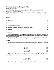
Fig. 2. Magnetic field H as a function of position z for three field configurations, as indicated.
column were taken at t = 125 ns. The input microwave pulses for all the configurations had the same temporal width, peak power, and carrier frequency as given above.
probe and the sequential spatio-temporal data acquisition were automated with the use of a computer. For the data presented below, the YIG strip was 7.2 µm thick, 2 mm wide, and 30 mm long. The film had unpinned surface spins and a narrow ferromagnetic resonance linewidth. The input transducer was 50 µm wide and 2 mm long. For the spatial scans, the resolution was about 100 µm. The spin wave pulses were excited with input microwave pulses with a temporal width of 35 ns at a carrier frequency of 5.515 GHz. The nominal input power applied to the transducer was about 32 mW.
The data in graph (a) show that, after propagation over about 4 mm or 106 ns in an increasing magnetic field environment, the pulse carrier wave number increases significantly. An analysis of the wave forms shows an increase from 175 rad/cm at about 1-2 mm to 275 rad/cm at about 5 mm. In contrast, the data in graph (b) show a significant decrease in the carrier wave number. Here, the change is from 175 rad/cm at about 1-2 mm to 50 rad/cm at about 5-6 mm in a spatially decreasing field. The two waveforms in graph (c), however, show similar carrier wave numbers at both time points. Note that, for the data in graph (c), one has H ≈ 1270 Oe at the 1-2 mm and 5-6 mm positions. The data in Fig. 3 also show that, in all three cases, the spatial width of the pulses remains moreor-less constant in spite of the non-uniform H ( z ) .
The experiment was preformed using three specific non-uniform H ( z ) configurations. These consisted of fields that (a) increase with z , (b) decrease with z , and (c) have a decrease followed by an increase, or a sag. A standard Hall effect magnetic field probe mounted on the scan stage in place of the pickup loop was used to map the H ( z ) profile over the YIG strip. Figure 2 gives quantitative maps of the three H ( z ) profiles. The z = 0 reference point corresponds to a position about 1 mm away from the input transducer. For the decreasing and increasing configurations, the overall field change over the length of the strip was about 20 Oe. For the sagging configuration, the amount of the sag was about 5 Oe. While these field changes are relatively small, the data below will show that they lead to significant changes in the carrier wave numbers for the spin wave pulses.
The analysis of spin wave pulse data similar to those in Fig. 3 for a full range of times yielded quantitative profiles of wave number k versus position z for the three configurations. Figure 4 shows representative results on k ( z ) for the three field cases. The profiles demonstrate the qualitative observations noted from Fig. 3. In graph (a), one sees that k is a clear increasing function of z , while graph (b) shows a decrease and graph (c) shows a sag. These k ( z ) wave number versus position profiles demonstrate a nice match with the H ( z ) profiles in Fig. 2.
3. RESULTS
In contrast with these self consistent k ( z ) and H ( z ) results, it is found that the carrier frequency of the spin wave pulses are largely unaffected by the field changes. This was ascertained from temporal wave packet signal measurements for a range of fixed positions along the strip and a Fourier transform analysis of these data. This result is significant. It means that the spin wave pulses
Figure 3 shows the spatial evolution of spin wave pulses for the three different field configurations and at two different times, as indicated. The plots show normalized spin wave signals as a function of position. The waveforms in the left column were recorded at time t = 18.7 ns, relative to launch, while those in the right
2
a) Increasing field
350 250
0
0
-1
-1 0
2
1
4
6
8 0 2 4 (b) Decreasing field t =18.7 ns 1 t =125 ns
0
6
Wave number k (rad/cm)
Amplitude (AU) Amplitude (AU) Amplitude (AU)
(a) Increasing field t =18.7 ns t =125 ns 1
1
8
0
-1 0 1
2
-1 8 0 2 4 (c) Sagging field t =18.7 ns 1 t =125 ns 4
6
0
6
2 4 6 Position z (mm)
8
100 0 c) Sagging field
140
100 0
2 4 6 Position z (mm)
8
Fig. 4. Spin wave wave number k as a function of position z for the three field configurations, as indicated.
-1 0
b) Decreasing field
200
120
8
0
-1
150
0
2 4 6 Position z (mm)
8
millimeter wave pulses, pulse chirping, and other microwave pulse manipulations.
Fig. 3. Spatial waveforms for the spin wave pulses for two different times, t = 18.7 ns and t = 125 ns, relative to launch, and the three field configurations, as indicated. The input microwave pulses had common durations and carrier frequencies of 35 ns and 5.515 GHz, respectively.
CONCLUSIONS The high resolution time- and space-resolved imagining of spin wave pulse propagation under spatially non-uniform magnetic fields has been achieved. It is found that, in a non-uniform field, the wave number of the spin wave carrier changes while the frequency of the spin wave carrier remains constant. Specifically, the wave number increases in a spatially increasing field, decreases in a spatially decreasing field, and is reversible for a more general re-entrant field change. These field dependent wave number properties present potential microwave signal processing applications.
generally will maintain the same carrier frequency, even as it freely propagates in a changing field environment. It is important to note that these results are for H ( z ) profiles in which the overall change in field was relatively small and the fields were always co-linear with the strip axis. As a consequence, the group velocity of the spin wave pulse is relatively constant over the more-or-less linear propagation path. It is also important to emphasize that these results are for the specific case of backward volume spin waves. The response would be completely opposite in the case of surface spin waves, for example, that applies when the static field is in-plane and transverse to the direction of propagation, or for forward volume modes for which the static field is perpendicular to the plane of the film. In these two cases, the spin wave frequency ω k is an increasing function of k . It will be important to examine the spin wave propagation dynamics for the gamut of possible vector field H ( z ) profiles and the wide range of ω k (k ) responses that can be achieved by these variations.
ACKNOWLEDGMENTS This work was supported by the U. S. Army Research Office, MURI Grant W911NF-04-1-0247, and the Office of Naval Research (USA), Grant N00014-06-1-0889.
REFERENCES Kabos, P. and Stalmachov, V. S., 1994: Magnetostatic Waves and Their Applications (Chapman & Hall, London). Stancil, D. D., 1993: Theory of Magnetostatic Waves (Springer-Verlag, New York). Wu, M., Kraemer, M. A., Scott, M. M., Patton, C. E., and Kalinikos, B. A., 2004: Spatial Evolution of Multipeaked Microwave Magnetic Envelope Solitons in Yttrium Iron Garnet Thin Films, Phys. Rev. B, 70, 054402 1-9.
Large field changes and propagation geometry variations may be useful for wave number control, group velocity control, and dispersion control, not to mention options for the tuning of the nonlinear magnetodynamic response. These effects have important possibilities for new classes of microwave devices for radar and signal processing applications. Examples include wave compression or wave expansion for microwave and
3