I I I I I I I I I
I
I I
I I
I I I I
I
Novanbar
REI
Board of Public 'Worka
237 Pl"OSpoct straot ,Nol'tham,pton, !-lassc.cl1asetts
01060
5. 1974
lJo~ton Roport on \1astowater 'l'"re:xtment Plmt
and Seweraeo System
The Division of Water Pollution Control in respon:;;e to a rerr.. t eat m.~d9 in your lx--..half by \:lli:tt:ln....1 3! 11owG.l"d. Inc., Concru1ting i.:ngineers, has rovim.red the above rcf'crcnoed report on eA:pansion of t:oe wc.stc\ow:ter tre:?:tr.wnt plant ;:;':'ld othel" work on thct se\JG1"U6E1 sys'tan. lJ:he report ia enti tledl REPOl:1T ON SEh'ER';QE 5Y.S'll!l\!
1,1Oi\'l'lUlf.lPTOH, IlJ,.sS.
\..lII':i}1.t;.r /):, lroUi;f{Pt r,~-;.
El~GIln~S .:J:ID iJ~Hlr~TS
REGISrulF.n f.l:;'CiCES3ION.L L:R1Ib't'..:;}·;R
Hi1SS.
lID.
2;~20
The roport deals with the upgr~i:l'lg ~ oXpc.nsion' of the exioting "''':lste
water trc::rt:nc:lt plant in order to proV"itie :for the tu:turo w.;;,stewut~r tl'ot.tmo.nt
ncode of the City c.;,nd t..lw ~o.,.n of \iillicIDsi:Jur{,;. .
Tho existing wastewater treu'bncnt plnnt. is a. primary tx'Sdl'DC,n.t plrult wi th ::;.or<1tc(l. 31'1t cl'lZlllbers, prlml'.ry natt.li:lg t[iru~e, hCilted anuerobic cludse diGosters, .Jut sludge ~"il".g beds. li.'ha report, proposes th:d:. t.he nxisti!o.?; prim£.ry plant. be upgr:lded to u uon.'lantiorw.l .uctivn:tcd sludge plt:urt \"lllich "dll r::erve <.'.."1
estimv:ted Nortlu,mpton pol,Julat.ion of 35.000 people and a \dlli;,:'msfAtrg popu.lction of 1.}ltO people.
The u,pgrudGd plaut will include grit removal 1'a.o11itiof.l. prim.'ll""'.{ settlillg tnllks, ael'u:tion ~.nl\..9. secondary nettling t;;:,nks, chlorilu.tion facilities and all effluent pur:tping station. 'i'he slu
Tho re;JOrt cleo inoludes a. InSetsI'
GO\lEJr
plan :for t.'1e city, tQ UJ,).3l""ide
Mid expa,l1d tho eoW'C'.ro"gc Slst-an. 'l'h9 report indioa.teD f i va pbl'.305' of sewer construction C!lld reco::lUQi.1ds that ph:loa I an.d phase II be 'lmde~en n.~J tho 01 t;r
I I I I I I I I I
Boc.:rd of hlblic I.':orlw Hov~1bor
5. 1974
SV\."nl.", ,~'1d CCJnut:."'LH;tioH of: 1~5)J linc.;1r I.'t:.et Qf 2 1j. il:ch d.i.:!1l1CtCl" h.l.V'CI'o,idc ]JX'1ve Intercoptor, mld 15,1)0 1imlLll." fo~t of 2,11 i1.lch di'J1Jf..rtcr .;.pru!JJ ~·tr1;l!~t Int«:ll.'CtCptor. ':rt1.O pJ"OJ,JOBod \-Drl", U!Loor i'1:ulno II cOnGt.lUo'hOll :i.nc1uclG[J~ ~;17U liuo<.U'" feet OJ.'" ;;6 inch l:l!U 2020 li:no.;U' feet of ).) inclll·iill ll.iva:l.~ ll.:l.-torcoptor; 121·;0 lil'.l.O£l.l" fr::l':Jt ot 12 i!'loh, l05~) lin~JJ." ieo·t crt l;~ :inch, l'jOiJ lUJ.cml.' ftH::1; cl 16 1i~ch. 17G{) 1.in~ur feet of 24 inch, 'rG.00 linear feset of :yJ inch UlQ 110;) line;:a' 1'~et 'Ji' :Lr':..cll. Fort Hill Int~l'C~;;>'i:Ior; S5W liuGt:r ieet of' J i:l.ch, ;:'!tW liw;~:;i." f('!9t oj; 2" inoh,
36
2:;:,0 lint.);::;r foot
(laCn
of 10,12
c~»d
14 inch
vi~j:::O!!
in
desi{7w.to.:l 1;,wthB!nptcn H.oad
lnterc~to~:·; Lovcfield btl.·t:!ot :t?umpi.ng ut~.t:lCl1 ,:.;nd 2)£iO lincr..t' '£f.wt o$.' J :incl~ force1'.llld.."'lJ ro1d 5'l70 li·\J~·!',r foet. oJ: (; ;L.'Ul.F}. r.:eh"tlr toO aer"rc L.;,;..o;c ;!!("':1')r:ic:.~ ",i"U;'~I; ..
'llie DiviL,ion of WA.tor IJollut;ion 0o:ntrol Gives f~cner.:l q"'Pl~V'G~ tl) thG l"'oport \ill th the pl"Qvi~io:n tHc~t ct:fo:.:;?i :£':il:.I.::1 pl~;.f::llnG is &t'~J7tcd ·~fJ tollo\.riu:~ :1..n:f'ol-,:ni4tio.r.i. ,(1.1.11 ;"0 ::'''J.I::.tQitt.~ fer :revJ.0~'l b.I"d. c:.p.owv<.Ilt 1. PfZdcru 201 1,'.;1.cilit1ta
!>l.annir~
H.o(!Uira:.n'3nts
irulludiY~
but not 1i::.li t.Go:" 'tol
it :;.n.cc..ns.oJ.''Y
I
t)
Ir!:~;""i~ i.,;\)llt ,1000VCl,"1
0)
6c-wel' \Jue (;harg;oa
d)
r~nvironmontu
l.s:JenGmOOt
eJ l?n.bli.13 i>a:rtioipatio'!'\ Heq:.l'lremmrt. 2.
I I
3cc
I
Ji.
I
I
I I I
':the proposed \;:ork w:d.cl" Ph.<:·.f>'l I inuluucs rE:ptJ.l' of tho King street
CM t\'U'l.d thaa.
...~ddit..i()nnJ. inionaation 1'Cga-(lil'l0 t.il0 proposed cutfi111 inc1.u..:..iiug bydr';"ulic pl:'01'110, ..nd en CVi'Un..rtJ.Dn of. i:.i!c nti;;t:~i':; vntfrT!. • .:\.100, i.l disQ'ussia.."1 of the j'l-:'l~f (1.i.'.:OT{!i.(.'n 1;,0 t~o .fl?c.d p'.:.;:t;::lir.g str..tiuIJ. during perj,ods 0:1:' 1'1()odll1;'; in ·"hQ I-all {;: CQ!Ull!3ct.iC'.J.t
Itl.Vel'ih j."eg~.l't')i:n.'~ Vt~l~lr.ln;! ~i1\d nt.':f·xm:;fth ot 1'101.";3 to i:J:.I..a t·l'Q('~U.'II311't plant. !~~1:fel""imee is miJae 'to t~i1e H.:';';.l.i.:.l>.C.C. Cd.::.tCG fo~ !..'efiiU'l of' \':[tot.a
r40re dntailGd infon!lation ox.1.atirl~ W,:.1S~w..'Lt.cr
W~:tol'
'J.'l't:1a:tmont.
PJ.L'.l:~tt
ChJJpt0:'
:r. -
.L.;qctiO!~ l.~llj.
a.
pu)."/;,h~r infm::!llt,tion tlUl.;"rt be sulru ~;ted b,:,:fo:::"Q clotm:'mi..r:D.tion 01' ali!;ib11:1. +.y to!' :ferier<>~ r::nd t~t£i.te gr.r.l'rt pal:ticip.r,.~;i(,'.n cc~n
00
de.
JD;'...
T".nan:.lS C. CO I
lbs9uchuoett;a l)orw.rtmc.!lt c''!: f-J.blic .
~le,!l t.h
\~hi 1:a::1.:n {~ iJOl-ll"tN, (;Ofl.mU t:i.ni) L:n,:;ll:t.GUl:r, f.;;.n\rl;('O~wy')'LtD.l
lXXl.
\·m ~~.e
t-'rotel)t.ion
j.g~HCY
-.
Hcl;~~ilion
Uil'C)\}t,.·.r
,
I I ,I I
EST. 1869 - INC. 1924
Robert T. lones, President C. R. Wickerson, Tre.surer C. Roger Pearson, Ch~irman Paul F. Howard, Emeritus
Paul C. Bucknam, Ir. Anthony Chiaravelotti Elias A. Cooney Brewster W. Fuller Myles F. Howard Frederick D. A. King. Ir. lames T. McDonough How~rd R. Perkins. Manager lames A. S. Walker, Arch. Officer
Arthur T. lucchini, Controller
ASSOCIATES
WHITMAN & HOWARD, INC. Engineers" and Architects.:: . 19 BROAD STREET, BOSTON, MASS. 021'10
Board of Public Works
237 Prospect Street
Northampton, Massachusetts
•
TEL (611) 426·6400
Gerald T. Carey T. T. Chiang, Ph.D. Robert E. Crawford Donald f. OMgie Charles C. Ellis Ernest H:Fagerstrom' Robe rl Hickman George A. Howland III Arthur liatsos James A. little Edward R. Mayer Steven I. Medlar james F. Murphy loseph A. Murphy
E:
01060
Gentlemen: In accordance with the terms of our contract with the City of Northampton dated January 17, 1974, ~. . e are submitting herewith our "Report on Sewerage System, Northampton, Massachusetts." .REPORT SUMJ1ARY The City of Northampton is presently served by an extensive municipal sewerage system constructed in the built-up portion of the City in the Mill River Valley. Treatment of the collected wastewater is accomplished at a primary treatment plant off Hockanum Road. Some of the system is combined, but this condition is being resolved through a separation program initiated by the City. This report evaluates the existing sewerage system and examines the need of expand~ng the system to service the remainder of the City. The existing primary sewage treatment must be upgraded to provide secondary treatment in accordance with current federal and state regulations. The possibility exists that an even greater degree of treatment, defined only as "best practicable treatment" may be required. The application of best practicable treatment technology is a requiremen.t of the Federal \'later Pollution Control Act Amendments of 1972. l\t this time the Environmental Prot.ection Agency (EP.:".) , which is charged "li t l - administering the Act, :-:15 not defined in exact terms the meaning of "best practicable" nor issued guidelines on the nature of treatment works which would be capable of providlng secondary 'treatment and be adaptable to upgrading to provide a higher level of ,~astewater purification.
I
I
I
I I
I
I I I I
I
·1 I I I
I
I·
This report will concentrate on developing a system of sewers
capable of relieving existing overloaded se\'lers and providing capa
city for future City-wide expansion and regionalization. Careful
review has been given to previous sewerage reports prepared for the
City and to the City's proposed master plan.
Estimates of costs have been prepared for all facilities pro
posed in the report. Phases of construction have been established
on the basis of greatest need ~nd logical sewerage system develop
ment. Project costs have been estimated and the possibility of federal and state grants have been 6iscussed. Various methods of assessment and financing are also presented. RECOr-rtfvIENDATIONS It is recommended that the City take steps leading to the preparation of construction plans and specifications for selected, required facilities. Federal grant funds may be available to assist in financing the work. The City Vlould have to file a Step 2 EPA grant application. One requirement which must be satisfied prior to the filing of the formal applications is the !:)C'.bmission of a Facilities Plan. Work to be accomplished under the Facilities Plan includes an Infiltration/Inflow Analysis, and, if necessary, a Sewer. System Evaluation. The Analysis should be undertaken as soon as possible so that the subsequent steps in the preparation of an application will not be delayed. The guidelines fer Infiltration/Inflow Analyses are currently being revie't.1ed and changes in the existing guidelines are expected shortly. Upon issuance of final regclations by EPA, the City will be able to determine the scope of the work involved. Upon resolution of the Facilities Plan it is recommended that the City endeavor to undertake the work described under Phases I & II. Particular attention should be paid to the requirements for the Mill River interceptor. This sewer will serve as a regional pipeline through \.;hich wastewater flo,;.;s from Williamsburg will be conveyed to the proposed secondary wastewater treatment fccility. Estimated project costs for ?hase I & Phase II are ~'O,220,OOO and $4,110,000, respectively. The Cityls share of these costs would be $2,540,000 after appropriate allowances for federal and state grants.
I
I
I
I I I I I I I I I
I
I I I I I I
Although the preliminary plans, as presented in this report, contain a number of pumping stations and several miles of gravity sewers, and force mains, it is not recommended that the City con struct the entire systenl in the near future. It is not presently necessary nor is it economically feasible to do so, but the systems have been presented to show hm·, the City could most economically be sewered, should ·the need arise. It is recommended that, as the sewerage system expands, the number of qualified personnel in the Sewer Department and at the Wastewater Treatment Facility be increased. This is important, since regionalizat.ion appears to be imminent and the increased level of treatment will require more attention and expertise. We wish to acknowledge the cooperation of the entire Public Works Department, and especially that of the City Engineer's office and the staff at the sewage treatment plant. Their help has been invaluable and has enabled us to compile data for this report. We feel that this document presents an organized plan under which the City of Nort.hampton may proceed with a program to expand the existing sewerage system. Respectfully submitted, WHIT~1AN
JFM/kn
&
HOWARD, INC.
I
I
I
I I I I I I I I I I I I I I
I
I
TABLE OF CONTENTS
Page No. LETTER OF TRANSMITTAL
I.
II.
INTRODUCTIO~l
A.
SCOPE
B. C. D. E.
METHODOLOGY OF REPORT ••••••••••••••••••••••••• TOPOG~z\'PIIY . . . . . . . . . . . . . . . . . . . . . . . . . . . . . . . . . . . . . EXISTING SEWAGE SYSTEM •••••••••••••••••••••••• S'rORM WATER SYSTEM ••••••••••••••••••••••••••••
IV.
V.
1 2
3 5 7
e
A. B. C.
S 9
ZONING •••••••••••••••••••••••••••••••••••••••• POPULATION . . . . . . . . . . . . . . . . . . . . . . . . . . . . . . . . . . . . . . .
WATER CONSUMPTION ••••••••••••••••••••••••••••• SE\vAGE ~"'LOWS ••••••••••••••••••••.•••••••••••••• HYDRAULIC DESIGN ••••••••••••••••••••••••••••••
PROPOSED SEWERAGE SYSTEMS •••••••••••••••••••••••••
12 13 17 21 21
A. REGIONAL CONSIDEP-ATICNS ••••••••••••••••••••••• B. GRAVITY SEWERS . . . . . . . . . . . . . . . . . . . . . . . . . . . . . . . . . .
C. PU1>1PING S'l'ATIONS AND FORCE MAINS •••••••••••••• MODIFICI1.TIONS TO THE PROPOSED ~vATER POLLUTION CONTROL F .Z!..CI LITY ••••••••••••••••••••••••••••••••
28
ESTIMATE OF COSTS AND FINANCING •••••••••••••••••••
54
A.
54
B. C. D. E.
VI.
............................................. .
1
DESIGN CRITERIA
D. E.
III.
••••••••••••••••••••••••••••••••••••••
GENERAL ••••••••••••••••••••••••••••••••••••••• r."'EDERAL AND STATE AID •••••••••••••••••••••••••
23
38
••••••••••••••••••••••••••• ,." •• ,. ••••
62 66
ESTI!'1A'l'E OF COSTS ••••••••••••••••••••••••••••• FINANCING • . , •••••••••••••••••••••••••••••••••••
74
ASSESSMENTS
SU~~RY
AND RECOMMENDATIONS •••••••••••••••••••••••
Jl.PPENDIX SEWER USE REGULATIONS BO::::-::~JG LOGS TRIBu'rARYl'l.REAS PROPOSED SEWERAGE SYSTE1-1 PROPOSED SEWERAGE SYSTEM
A-I to A-I0 PLAN NO. 1 PLAN NO. 2 41 SHEETS
69
76
I
I
I
I
I I I I
I I I
I I I
I
LIST OF FIGURES Figure No.
Title
1
Population Trend
2
Infiltration Rate Curves .••.............•.. 16
3
Schematic Flmi Diagram-Tributary Areas
4
Rat~io
5
Sewage Pumping Staton:
6
Se''lage Pumping S-tation: Semi-Prefabricated .. 32
7
Typical Prefabricated Sewage pumping Station 34
8
Schematic Flmv Diagram - Proposed Additions
to Sewage Treatment Plant ....••..•..••..•..
52
Hydraulic Profile .•...•....•.....•.........
53
9
11
18
of Minimum and Maximum Flows to
Average Sewa.ge Flo\v •.....•.........•.....
Custom Built ......• 29
I,IST OF' PLANS Plan No. 1
Tributary Areas
Plan No. 2
Proposed Sewerage System
Topographic Maps & Sewer Design - 41 Sheets
~I
'I
I
I
Page No.
,
.
I
I
I I I I I I I
I
I
I
I
I
I
[I
i
I
I
I
LIST OF' TABLES
Table No.
rritle
Page No.
1
Design Data - Wastewater Treatment Facility
48
2
Cost Estimate .- Wastewater Treatment Facility ...
56
3
Cost Estimate - Proposed Wastewater Collection System •••..•••.•.•••..•.•••.••..
57
4
Total Project Cost ......••.••.•..••••.•••......•
70
5
Estimated Maintenance and Operation Costs
73
6
Estimated Annual Costs - Financing Pha s e I & I I II..................................
75
i
I
I
I I I I I I I I I I I I I I I I I
I.
INTRODUCTION A.
SCO:!?E
The purpose of this report is to present the results of detailed investigation pertaining to Northampton's sewerage system.
It includes an engineering appraisal a.nd evaluation
of the existing system as \llell as recommendations for extending the sewers to those areas not presently serviced.
Proposals
have been made for upgrading those sections of the existing system which are incapable of carrying the expected future sewage flows.
The extent to which municipal surface drains are con
nected to the sewerage system and the schedule that has been outlined by the City for their separation is examined.
-1
I
I
I I I I I I I I I I I I I I I I I
B.
METHODOLOGY- OF REPORT
The considerations used in examining the existing sewerage system and developing proposed sewerage extensions will be com patable with the City's recently completed planning study.
Use
was also made of the City's complete topographic maps and record plans of sewerage works.
Field surveys were employed to confirm
and identify critical elevations and pipe sizes. Questionnaires were sent out to major industrial plants and institutions throughout the City to help in estimating present and future hydraulic loads.
All previous reports, including the
evaluation of the existing sewage treatment plants, the report on the Mount Tom area, and the examination of the feasibility of regionalization of treatment facilities, are considered herein. A complete update of any modification on earlier reports will be described fully.
-2
I
I
I I I I I
I I I I I I I I I
C.
TOPOGRAPHY
Northampton is located in the Connecticut River valley at the mouth of the Mill River.
Its terrain varies in elevation
\0 from 120 feet in the meadows along the Connecticut River to 800 \~ ".. feet above mean sea level at the Westhampton boundary.
There are three major watersheds ,..,ithin the City.
Only
one of these, the Mill River watershed, is tributary to the
existing sewage treatment plant.
Since this is the largest
and the most developed, the City is very conducive to a gravity sewer system. Much of the area in the southern and western sections of the City drain toward Parsons Brook.
Because this brook flows
in a southeasterly direction toward the Town of Easthampton, it will be necessary to construct wastewater pumping stations at the municipal boundary when sewering this tributary area. Because the northeastern region of the City is tributary to the Broad Brook, a watercourse which flows northeasterly toward the Town of Hatfield, pumping stations will be required to convey wastewater to the existing sewerage system. Sections of the City lying within the flood plain, but outside the protective dike, are frequently flooded during the spring high water an6 upstream control measures have not sufficiently reduced the danger of extensive flooding.
In view of the flood hazard, it
is unlikely that significant development in this area will occur.
-3
I
I
I I I I I
I
I
I
I
I
I
I
I
I
I
I
I
The area within the dike is protected by a flood control pumping station having the capacity to discharge any antici pated runoff in the Mill River watershed. This briefly describes the general terrain in the City of Northampton.
Minor di
iculties in extending the existing
sewerage system int.o areas 'Ilith unfavorable slopes C.re also considered in this report.
-4
I
I
I I I I I I I I I I I I ,I I
'I I I
D.
EXISTING SEWAGE SYSTEM
The existing sewage collection system, as illustrated on the accompanying set of plans, consists of approximately eighty miles of 8-inch to 66-inch diameter sewers.·
Although the system
was primarily designed to carry sewage, there are catch basins connected to it contributing substantial amounts of surface run off.
In order to relieve this excess burden, the City has adopted
a plan for their removal which will be discussed later. There are two existing sewage pumping stations in the City and they have been evaluated relative to their present and future capabilities.
Both have been found to have adequate capacity and
will not require any modifications. The total wastewater flow from Northampton, which currently averages 3.2 mgd, is treated by a primary treatment plant.
Current
state regulations require that the plant be upgraded to secondary treatment by March of 1974.
The "Report on Nater Pollution Centrol
Facility,lt August 1970, recommends modifying the plant sufficiently to treat 4.2 mgd on the secondary level.
However, based on this
report, its design capacity should be increased to accommodate
t~e
average wastewater flow of G. 76 mgd ·.., hich is expected by the year 2000. An exhaustive investigation
~as
been conducted for the purpose
of locating the existing and pot.ential problems wi thin the system. Some of the more serious problems1.Dclude the Riverside Drive sewer
-
-5
I
I
I I I I I I I I I I I I I I I I I
which is undersized for existing
flo~s.
The Park Terrace and
Reed Street cross country se'l,vers have deteriorated due to set tling of solids.
Sections of the Mill River interceptor in the
vicinity of Smith College are collapsi.ng (portions of the 24-inch brick se\ver have already been repaired).
Structural failures
and excessive silting are major problems of the King Street sewer. The interceptor behind Dyke Road has suffered excessive deteriora tion.
Proposals for correcting these problems and for upgrading
the existing sewerage system where necessary will be thoroughly discussed in this report.
-6
I
I
I I I
I I I I I I I
I I I I I I I
E.
STORM WATER SYSTEM
Recognizing the need to upgrade its existing sewerage system, the City of Northampton is currently engaged in the process of remedying a longstanding problem.
'l'he correction is that of separa
ting the 165 stormwater catch basins that drain directly into the sewerage system. Catch basins connected to the sewerage system can overtax sewers during periods of heavy precipitation and snow melt.
Sewers and man
holes can deteriorate prematurely due to excessive scouring.
The
effectiveness of the sewage treatment facility is reduced because it must accommodate large amounts of stormwater.
Furthermore, catch
basins can become a convenient depository for chemicals and wastes harmful to the treatment process. The schedule proposed by the city calls for the removal of 93 catch basins between 1971-l974, 26 catch basins between 1974 1975, and 22 catch basins between 1975-1976. catch basins, 2 are to be sealed off entirely.
Of the remaining
The twenty two catch
basins that have not been accounted for in the above lie ol1tside the center of the city.
They shall be separated when adequate development
of those areas requires the extension of the stormvlater system.
-7
I
I
I I I
I I
I I I
I I I
I I I
I
I
I
II.
DESIGN CRITERIA A.
ZONING
One of the most important factors in the growth of a community is the intended use of available land areas.
The
City of Northampton has recently completed a new master plan
of zoning regulations governing the use of available land within
the city.
These regulat.ions Ciefine several general land use
areas: residential areas with lot sizes ranging from 6,000 square
feet to 50 1 000 square feet
1
business areas,
high\\'~ay
business
areas, industrial areas, and flood plain areas.
Consideration of these zoning regulations is of the utmost
importance in determining flows from a given area and in deter
mining the outer limits of the proposed sewerage system.
The proposed sewerage system for the City of Northampton,
as presented in this report, is the result of a careful review of
zoning laws, and has allowed for sewering that portion of study
area likely to be developed within the next 50 years.
It alsc
provides a means for conveying the wastewater from Williamsburg
to the Northampton Sewage Treatment Plant.
The report recommends
various phases of construction giving first priority to those
sections of the system which require immediate attention.
Areas lying within the flood plain have been considered non
buildable for the purposes of this report.
-8
I
I
I I I I I
I I I I
I I I I
I
B.
POPULATION
Because a direct relationship exists between population
and the quantity of wastewater generated, an adequate sewerage system depends upon an accurate analysis of a city's population. Therefore, some type of logical rationale must be devised for estimating the future population of the city.
According to census
information, the population increased by 1269 people between 1940
and 1950; increased by 995 people between 1950 and 1960; and de
creased by 394 people between 1960 and 1970.
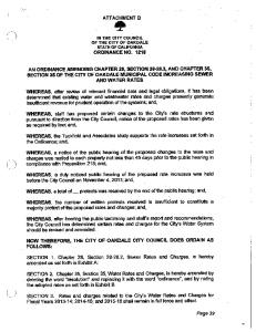
projections of
arithmetic and geometric calculations based upon available census figures indicate that the population 50 years hence would reach . approxlmately 32,100 peop 1 e.
. However, wlth the
~~
co~tructlon
of
Route 1-91 and with increased productivity in the entire Connecticut River Valley, it is reasonable to expect a substantial increase in the rate of population expansion.
Therefore, in predicting the
future population trend, we have allowed for a growth of 3000 people per decade as shown on Figure No.1.
Having assumed that this
increase in population will be uniformly distributed throughout the City, our calculations indicate that about 27% of the outlying areas will be developed and that presently developed areas will experience an approximate 10% growth. A questionnaire was circulated to institutions within the City so that an accurate estimate of the present institutional population could be ascertained.
Information relative to forceeable
I
I
I
siz~
-9
I
I
I I I I I I I I I I I I I
expansion at these facilities was likewise requested.
inhabitants of these institutions are listed as residents of the City by the Census Bureau. From the responses it was learned that very little expansion of the existing facilities is planned within the forseeable future. For the purposes of this report, therefore, the total population figure reflects the maximum institutional as well as the City's resident population.
This approach is consistant with that used
in the "Comprehensive Plan Summary" prepared by Metcalf and Eddy, 1972. It is estimated that 75% of the inhabitants of the City inclu ding all the institutional population are presently served by the municipal sewerage system.
If the proposals of this
repor~c
are
implemented in a systematic fashion, the sewered population will reach 82% and 99.6% by the years 1993 and 2025, respectively. Adequate septage receiving facilities will be provided at the Sewage Treatment Plant to accommodate the small percentage of the inhabitants not serviced by the sewerage system.
The facilities will have
sufficient capacity to receive 5000 gals per day.
I I I I
Presently,
-10
I I
I I I I I I I I I I I I I I I I I
1-------.--.-----.,.-. - .,.-.- - -.'.
I
I
I
--I
I
I 01
I
2! I I
~I ::Jj
(!) __ I
lJ...i
I
I I
I I
(f)
fl-
C)
LU ef) :J
2.: Cl
lLl
,..."". u_
I
U)
. .::c
a: 1- .. _
<1
.._
W
>-
« (/)
-» ~
0 1--
c:::::
... -:;.. , f:. __
o:"."l ~)
--_.1, , ____J'
0..
C) CL
r"
1:',
:2:
<[ ~L ~
... u .. "
0:: C) -..,.
r..:.
0
w
('>
0
0
0
0 0 W
()
0 0
0
0
0
~~.
cf')
()
0 0 0
8
0 rr,
0
~~
~
N
NOl1\1lndOd I
!
Vvr-I!TM/\N ENGIN[En~.
\~
HOVV/\P!), iNC.
,-k AI"\CHlTECTS
bOSTor~
Mi\3S.
-"--'-- -'--1
FI Gunf.
~~
O.
f
r
~-"_P_"'-""----'''''-'--''- ... __.. '....._......
;
I j
I
I
I I I
I I I I I I
I I I I
I
I
\-
\1
C.
WATER CONSUMPTION
Due to the fact that sewage is primarily composed of used water, it is important to locate the major users of water and to review their records of water consumption.
This enables the
engineer to adequately size the sewerage system for their needs.
Water consumption records vital to this report were obtained from all the major instit.utions and industrial plants through the use of specially prepared questionnaires.
In addition to
water consumption, such institutions as hospitals and colleges were asked to relate the number of residents at the present time, total number of beds available, and information regarding expan sion of facilities.
Compilation of the data has revealed that
these institutions have reached a stable population and consume an average of approximately one million ga.llons of water per day.
Industrial plants were asked to
fu~nish
information regarding the
number of present and future employees, total land area, water consumption and usage, method of vlastewat.er disposal and quantities, pretreatment of industrial waste, and particular disposal problems. From this information, we were able to provide adequate sewer capacities for these regions of the city that require special con sideration.
-12~·
I
I
I I I
I I I I I I I I I I I
I
I
I
D.
SEWAGE FLOWS
Sewage flows were established by considering the expected domestic and institutional, industrial, commercial, and infiltra tion flows.
An average do~nestic flm'1 of 100 gallons per capita
per day has been used as a basis for design.
Although present
water consumption records indicate that the actual figure is somewhat lower, the general trend is toward increased water con sumption due to the greater use of washing machines, garbage disposals, dishwashing machines, etc.
Because of the treatment of
institut.ional population as part of the City I
S
total population,
sewage flows generated by that section are included along \-vi th the domestic flows. Se\-'1age flows generated by existing industr determined from the ques·tionnaire.
1 plants vlere
These questionnaires vlere
directed at developing information on present water usage, employ ment, land use, production estimates and current wastewater dis posal practices.
Attempts were made to estimate any future
grow~h
of these existing facilities and to make allowance for anticipated flows.
The predict future industrial flows from industrially zoned
but yet undeveloped land, \'1e have allmved for the contribution of 2000 gallons per acre per day.
Likevlise, \Ve have allov.7ed for a
wastewater flow of 2000 gallons per acre per day from,commercial
and business areas.
-13
I I I I I I I I
I
I I I
I I I I I I I
An important consideration in the analysis of a sewerage
system is that of groundwater infiltration.
The quantity of
infiltration flow varies depending upon such considerations as the age and quality of the sewer pipe, the w'orkmanship that went into its installation, and the amount of maintenance that was given the system.
Other important factors affecting the
q~antity
the length of sewers, the permeability of the soil, and the
are nurr~er
and condition of joints and house connections. A detailed investigation of one of the major lines in the city has been performed by the sewer specialist, Penetryn Systems,
Inc.
From the findings, as presented in the Feasibility Report:
Regional Sewerage System - 1973, it is reasonable to assume
t~at
a
considerable amount of infiltration is gaining access to the system
through cracked sewer pipes and poor joints.
Due to operational problems with the flow measuring device
at the Sewage Treatment Plant, accurate data on existing flows is somewhat sketchy.
During periods of severe storms the flm-l in
excess of the plant capacity is bypassed within the plant to the
Connecticut River.
This bypassing action which can be of long term duration
during wet weather periods causes a surcharge condition that pro hibits the use of the existing Parshall Flume.
Likewise, high
levels of the Connecticut River also reflect through the system and create :roblems in the flume.
~~stly,
cold weather
problems with mechanics of the flume measuring device.
cau~~~
The pro
posed modifications of the existing Sewage Treatment~plant specify the replacement of the parshall flume with an electromagnetic flow meter.
-14
I
I
I I I
I I I I I I I I I I I I I I
One can draw a rough correlation between the relati.onship of infiltration and recorded plant flow when it is realized that approximately twenty thousand persons. are served by the facility and average flows are about 3.2 mgd.
An infiltration rate of
1.5 mgd for a system (approximately 80 miles of municipal sewers)
the size of Northampton's is not unusual.
Unfortunately, because
of the interconnection of drains, no assessment can be made of the condition during the periods of the year when groundwater is highest. As a means
of estimating the present and future infiltration
into the sewerage system, we have used the graph shown on Figure No.2.
This graph, taken from "Wastewater Engineering" by Metcalf
and Eddy, is a plot of infiltration as a function of the service area. It should be noted that these estimates were made in lieu of an actual infiltration/inflow study.
The resul·t.s of such a study
if taken before the separation of catch basins from the sewerage system would be misleading because the pipes transporting stormwater inflow are considerably less water-tight than sanitary sewers. Additionally, because of the significant degree to which the system
is combined, it is virutally impossible to ascertain the impact of inflow from any private drain or roof leaders.
-15
I
I
I
I
I
I
I
I
I
I
I
I
I
I
I
I
I
I
I
------T-·'-7~f~---·-·
·'7-1------.---]
o
\.}
o
~
l/ /f I - III~
I .
.« ~ i l l ~Q/ II l,~
I ;/1 . /
Lu...J
!.
if
/
~Ol /
::) Ii!
I,
I
I
t /
I, I
', . .
I i
1
, //
Ii /
>
l_-I
_W_"" - - ;
{
/
;
/11
I
,
I' 0 .0 Cl ~
:. ,..J....
!
I
"! Z.
;
(.)
/
I
_
~
I i I
(0'" • VI
(;J
'
1
c·"
. t·,, , <1: ,~I,.'
..... (
I
I
'
~
i I
t_J
t)
i rc
I. / I
,'l',
_)
/ I ,
l,,... ;
(:)
!'"
l'
" I.'
-_. I
LJ
<-' ~f)
I! l
U
() !
I
.
l' ;
U
,.. '
u.:
tlJ
r-~
;
i
[0"
-', \..j
\
I
l I I
I
I
l.
j
>0 tr: ...J ::::.0
u
I
I!
II
I
! i
~:j'
..
-j
1
I..L.
-
en
'-~
-'. ~
..
:,.. ,
.-.L
.. "', .+. ~.
-
:::~ )--.
I:;)
o C\l
I
.
>
L '.,) (.,
L..,y
,:,
:0) ':" fl: '-'
0, D d 5
r- \ () I . '-! U I -1 I .:j''\ 1\1 "J. \I CJ ••~. I ..I !'
. j •. 1
<':' _.f
fJI
f·
w :i:
f\l D. H 0 \/V"l\
;
-
.c..
I-I
_--'-__ -'- __ ~ __._ J
I
-.--~--.-
f': 1 , ,..J
I 1
I!
I
o o oIi)
I
::.:;'
.:r
:r
(/)
I
!
!
"I.
.
'.:J I. i /'
II
f~..
I
I u) I / I cr: I I /
!..d I
l'..! ,
I
I
I I I I I I I I I I I I I I I I I
E.
HYDRAULIC DESIGN
All proposed sewers have been designed to collect sanitary sewage from houses, cottages, businesses and industries and to convey it either directly or through pumping stations t.o the water pollution control facility.
The sewers are designed to
collect the sanitary wastes onlYi they are not designed to accom modate any s"torm drainage or roof, yard, cellar, or foundation drainage.
A single such connection may contribute a greater
quantity of water than an entire household.
It would not take
very many of these connections to overload the system. The design of sanitary sewers will be for the year 2025, I
the usual 50 year design, and they will be capable of handling the designed peak sewage flows.
The drainage areas are illustrated
on Plan No. 1 (Appended) and also shown schematically with their respective peak flows are shown on Figure No.3. The relationship between minimum, average and maximum flows has been determined by using the curves plotted on Figure No. 4 entitled "Ratio of Minimum and Maximum Floo;,.: to Average Sev;rage Flows.
II
This graph has been obtained fr.om actual gauge measurements made throughout the country.
Because the peak to average flows used in
this report have this conservatism, the pipes are designed flowing full at peak flow rather than on a partial flow basis.
It is believed
that this .l.l1ethod. of design has ach.J..t::!ved an economical networK. of adequately sized pipes.
-17
------------------r---,
!£:l !I 10 <, < I I --i
Flow in
mgd.
2.89 (Typicol)
t:~
i ,t..
f'
_~ _~
{J1
I
!
I I!;J » L I
..
i", ?
--.
! C,
I
I~ ~I ! r) I I 'n"l
,:"'10'I !I ,. ,.'! ,':- 'I J <~: 4 i
J,
t;
~
-I
d.r
_
;
i
3 "7) \
Ii
~'''! ,-- !
i .;<-
'..-
r) I
:~: ,
W .;;l.56
I
.-
'l
'.
'-._.~,03""
(22)
·~/.06 "r~.3r ~
/
/.."--'"
jII-1I
(~ ,i::) )
~ '",_~/'-.'-. c,~ ~/
~
' - J":.J ~
-
~2
:-:~r·46
o~
-'"
3V :.; '7.
4'
cB~
r
~
.. 1
\.)"J'J.,
J5.C~
t'"\
/ \ /" 31 ' ;; 1'1') " )~\ .) V
I
-
f'9 ) \i._~,,,,3.8;~. "'/
\
,
/, q '> I'., U ,I
i
t:\
(45) 4 ~t)) L - _
I
!
V
31
---@ . . . (47) 17 --rPs0 4,6 -ff-:g--~ ITtj.~--I:.~;...I;:,; ~
1
1
"
(,j
C ::0 f11
......
o
"1
I
\.
~.'.
\
-
...........,
......;
/
.."'\
•
)'@
",/
7.25
9.60
I I/~' [~I 719- \ .80r;-'\~ '2.8" .'- . go
~ ,
. . . . . . . . ""
I
r - (....
. '0 '::f
'-r, I':-----. '. \'Ur--'i":» \ / ',-
. ....,.,-_...-'\, " n 7 ./ '(:.1 O q l-,: ) - , " ' . : . . . ( ; _ . _.../ - - " , o _ · 5 2 0 ,.::;:,. , ." "',~ _ Li. '7 • f---:;.-.,'\ .;,--;....)~~ 4.71 '-/ \. .I ..../ If"."} ,_,-"p,"}-.....i 4::; ___ ~_'_ _ __
--
'---'"'
! -_ .
.
'-............
"-',-
,_I
\
I '-
c-Y"
I
'--';
~
I
I
FLOW LISTED IS THAT FLOW ANTICIPATED IN YEAR 2025. r,_-) r' . -... • " -,-.:; \., f" ,-. . 1"i j._ ~ l1 !-...'. _____ _________..______' ._. '.. _
4~.
T R ! r:; U ........ _.-.-
/"'
I
f .--,
'
II
J
"..I. V
'-_/_--
\
!
-_._---- --------_ .. .._,,--------_._--
Ii
J.>.'O.92
F ,"'. . .")
l;'\
Y
t. ' ..
~ ,~
ro,..,,~) .~-~ •",. .~\ (~~ _'. ~__,_
.~_~W,_~"_
f; ;: i S
..,__...,~.
j
r-' ......
I.!... , /
,,-.
(;J
I
'/'I
/'-.... ( /: I ... v.!fr.: J . /i -,\
l:.; (.
0.37
8 )
\['-:1-' '-""
\
(h \
-
I
!I t.-----I
1-..
(4') "-=_/
(7~) /'
,.33.j~.78 ~/·./{[~6
1
t---.r::;----;
!i ,r
/ -;\
./~, '----:.~ "-;U~·· • . (~1.~9./ ,..~ I -y--, 14.87 ,3 \,. /' C I \ Q {. -, I 'L ,-,' Y \ / '--. ~··~;~i.62r-'_\ 14.77'/~-"67 ( I LI.~, 5 i - - - - - - i I 1 ',' '~/' ,,/ "/ . . ,
._/"'~.-\
'--
,
~ 4.58·r/
1/ t=:.J ) \
,~ \2h~ \t--;:-J,2 f \ /~--:; /,,}) 0,43
'--,/'\.,'\2. . 89
I
£
\ 23·,
(2i\,
\
-'J: 0 /. I
I ;,...)
I
~o
'- .',-3 itO ".6 3. (O
I 70
~ '.4~
Wi IIlomburg f7r \ I, ,,)0 j
>1
: UJ
'--
({)45
i -',
I
v
i
!' rn ~n
!
I.
10)/ \
1 I ~7 ..
• • "oJ
fJi\
1.03 rpst
2.IO,~~.-:-::\lh" I I ,)
) . ,""•
V
" -'l -~ • . -.
I p"
~O."..>
I,",,",
..
~ ~
1'0.40
/~
(t+
2,\ 11
\...:.. ~/
FIG U HE f J ~ ,--_.............. - .... ---_._._-_..._---------------.-----_._-,._..
I
I
I
I
I
I
I
I
I
I
I
I
I
I
I
I
I
I
I
#/6'
REPORT ON SE\\TERAGE SYSTEM NORTHlJlIPTON f
M.l\SSACHUSETTS
WHITHP.. N & HOWARD, INC.
ENGINEERS AND ARCHITEC'1'S
89 Broad Street Boston, Massachusetts 02110
I
------------------Icol z I
I
o I::::; .Ii:..
.<:.... .;:
-,!
,in j
Nl
-'-
.. ,
~
I~
i
I
Zj
I~
l!.l
1
,_ I I .. L. 00 , :
.
,
...J.
I
I
;-n r:
;-.- I
t
''''l
.AF~"
j
......... '
,-, ! ~~ ! » I
I " ,-l i ""J i I iI
I
-0 Ii j ,0 ;'1 i (:1 ,:- 1. (!O'
I .'.'
) 1 ,-; j
/'",
, :: ~
\,
--~.
'
~
~
~
.... ) '
I I
'!
jt"
,t
I:
-11
.:'- i
.
-~
('1=
~.
I
,""'\
,:,"
!
1----· I 1
c..~;
'~)
c; -.'
..... :;
ril
~ t--=±-t
r
I
! ---+---1
I I I I I II I I I I I
I I
I I IP
~ ~t--~ 2~t-_-f-
~
~ ',~~.
t=
..9.
...-
.8
..2:
I
I
I I I I
!
I I
I
I II
I
I I . f--~~,l':ltr F,=OWS
I
-f-~ ----"---t-ff~-~
I
i
I,
I
I I I
"
I
I
I
I
I
! .
I!
i
.
I
I'
I
-t--"-j
Iii
--I---'~'---
r-t-· -
I I
,
--f--
.
fP
I ..
I! 11
I
j------ -
l-t-- .
.7•._ -
i
~I I I I I ' I I -~~
+i-~
---I--
I
u
>
X I.e
I
I
nu~~ ~ ~+--i-tt£H_f11f' -t --r +--4 4
»
I, ;;>
o
I
I
3:
cIf .,'
,
I~+--LI
1
L---:--'i..-~
i-h I i+i-W~~ t-4-· i ~Htn~ .-t-, , ~2~~I-r~1+~ --IIl=r -1-rE' n , Ii! I Z T I TIl I T rt--1 1, . I - l '.. L!l --i .' C
.6 ._--
Z·5
.:>,
2'
.15
'1--
I
.4-
~ -
I
I
I
!
I
-t
IL__.-l. .15
jll
'
iTLLl_~,_~,
I I
I
__~--L-~-~MI,NIMUM !
I
I
l -r-1-i iI iI
i_I
I
.I
Ii
-I'
.2 .25.3
.4
.5.S:J.e.91.O
!.5
2.5:;'
4
FLOWS
I
I
.H--I
5
,-H
I
I
.
I
I
IIIII I
I
6 7 8 '.) 10
15
I
I
I
I
I
I
20 25 30
!
!
i l l ill
I
I
Ii!
40 50 60
I
L
00 JOO
AVERAGE DAilY DOMESTfC SE\NAGE FLOV,", IN M.G.D.
"r ,.
~::~.
0
..p.
J\ -r- to 0;= I t ·• R\ 1-\ ~ "-0 I
l __
U' Iru~• i AND
~JI A XIf:;; U ~it1 ; '\ I"t. \;J t:. SE\~U\GE FLOVV
~ i\f ~ I'll/ Ii\A 'I! I I '..J ! I 'i l f'\ \ / ~~; t"'" ;'-i.
'I,
FLO VI S
.-...~:
FIGURE NO.4
I
I
I I I I I I I I I I I I I I I I I
The system of sanitary sewers serving a community must be of a sufficient capacity in diameter to transport any size object which could enter the system.
The sewers must also be large enough
to facilitate inspection and cleaning whenever necessary.
Therefore
pipes smaller than eight inches in diameter are not to be used in the design of this sanitary system and pipes smaller than five inches in diameter are not recommended for house service connections All proposed sewers have been designed to carry their flows with a v(;!locity between 2 feet per second. and 10 feet per second.
-20
I
I
I I I I I I I I I I I I I I I I I
III.
PROPOSED SEWERAGE SYSTEM A.
REGIONAL CONSIDERATIONS
An important aspect of any comprehensive sewer study for any community is consideration of the question of regionalization of wastewater collection and treatment facilities.
The City of
Northampton due to topographical and geographical considerations is a focal point for at least a dozen or so communities who rely on the City for commercial and other needs.
From a sanitary engi
neering standpoint there is also the possibility that Northampton could serve as the center of a network of regional sewers servicing areas contiguous to it. Recently, there has been much discussion regarding the possibility of regionalization of wastewater disposal facilities focusing on Northampton as the core city.
As early as 1963, a
report was prepared for the Town of Williamsburg, which recommended the construction of a sewerage system in Williamsburg with connection into the Northampton sewerage system for treatment and disposal.
This
consideration has led to the completion of construction plans and specifications for such a sewer connection to the Northampton system. In 1970, The Town of Hatfield completed a report which investigated the possibility of regionalization but found that it was more desirable for Hatfield to construct and operate a treatment own bounda.!. ies rather than going
Ou
f~cility
a regional basis ,..I i th
of Northampton.
-21
within its ,-~ .. 2
City
I
I
I I I I I I I I I I I I I I I I
I
In April, 1971, a regional study was prepared by the LO\'7er Pioneer Valley Regional Planning Commission which recommended the implementation of a program whereby five communities namely, Northampton, Hatfield, Williamsburg, Goshen and Chesterfield would share in a regional facility in the City of Northampton.
Due to
the fact that some of the findings of this report were contradictory to recommendations of reports previously prepared for Hatfield, Willia'Usburg and Northampton, Whitman
&
Howard, Inc. was comndssioned
to study the question of regionalization as it involved the five communities. This report studied this matter thoroughly and, on the basis an economic analysis, it was determined that the most advantageous route for each of the five communities and for the five communities as a whole was by the construction and operation of three regional facilities.
One facility would service the Town of Hatfield; another
facility in Chesterfield would service the Towns of Chesterfield and Goshen and discharge an effluent into the Westfield River.
A third
regional plant would be constructed in the City of Northa.mpton at the site of the present facility and would service the City of Williamsburg.
'fhis report was subsequently approved by the Massachu
setts Division of Water Pollution Control on August 21, 1973. full and complete discussion of the findings is carried
i~
A
the report
entitled "Feasibility Report, Regional Sewerage System, Northa.mpton, Massachus€;,tts I Whitman
~',
Howard, Inc., Engineers and Archit.ects,"
dated January, 1973.
-22
I
I
I I I I I I I I I I I I I I
I
I
I
B.
GRAVITY SEWEHS
In the design of the proposed sewerage system for the City of Northampton, primary consideration has been given to upgrading and extending the sewers in the City's more developed regions.
After an evaluation of the existing sewerage system,
it was determin,ed that some sewers are in need of immediate attention. The interceptor in Riverside Drive frem Federal Street to the siphon crossing the Mill River near Willow Street is vastly undersized and should be replaced with a 24-inch sewer.
This
line is especially importan'!::. because '-'i t must convey the waste-water flow from the Town of Williamsburg to the Northampton Sewage Treatment Plant. Already overloaded, the siphon crossing the Mill River between Old Shepard Road and Arch Street is incapable of handling future waste-water flows.
Furthermore, the City has
already experienced difficulty with its operation. !After consideration of the anticipated waste-water flows from this area, it was determined that this siphon should be abandoned. As a means of eliminating the need of a siphon in this area, a 24-inch interceptor should be installed between the above mentioned siphon and the siphon
l~cated
-23
near Willow Street.
I
I
I I I I
I I I I I I
I I I I
Besides servicing the westerly section of Leeds, it will convey the wastev.Ja ter f low from the 'J.'own of Nilliamsburg, the Chesterfield Road area, sections of Spring Street, and Look Memorial Park. Most of the Mill River interceptor, which lies betw'een
-
Federal Street and Pleasant Street, lacks sufficient capacity ........... to acconunodate future wastewater flows. Moreover, sections of
-----
---"'!"----:-----~-
the sewer are experiencing serious structural failures in the
-----.
vicinity of Smith College.
Replacement of the faulty and under
sized portions of the interceptor will alleviate this problem. As shown on the accompanying plans, the diameter of this proposed sewer ranges between 30-inches and 36-inches. The section of the Conz Street interceptor from Smith Street to Mount Tom Road has sufficient capaci ty to convey the anticipa'ted wastewater flows of the near future.
out of the sewage in those portions of the sewer having slopes below the recommended minimum with the consequent reduction in capacity.
Th~
replacement of this sect.ion of the 24-inch sewer
is necessary prior to any extension of the interceptor and quite likely before the year 2000.
Additionally, sections of this inter
ceptor between South Street and West Street are vastly undersized relative to expected wastewater flows and will have to be replaced as needed.
For this purpose, the inadequate segments have been
isolated and suitable replacements for t,hem have been designed.
:1 I
I
However, solids are settling
-24
I
I
I I
I I
I I I
I I I I I
I I I I I
An analysis of the existing sev/erage system in the City's Fort Hill area has revealed that some sewers in this region are in need of extensive renovation.
The existing interceptor, which
ranges between 8-inches and 12-inches in diameter, extends from South Park Terrace to a point about four hundred feet Mount Tom Road.
b~yond
Due to the instability of the soil in this
location, sections of the se'>'1er have undergone serious misalignment causing a substantial decrease in its capacity.
Before considering
any solution to this problem, however, it should be noted that sufficient upgrading of this sewer would facilitate the servicing of the city's entire southwestern region.
For this reason, it is
advisable to replace the entire existing interceptor with a new 30-inch line.
In order to extend this sewer beyond the Mill River,
the construction of a 3-barrel siphon is required. Although the area along Easthampton Road is zoned for business, the lack of a sewerage system makes it unattractive to many types of businesses.
By installing a line consisting of 24-inch and 30
inch pipe and a pumping station to service part of Easthampton
~.oJd
and Lovefield Street, this area would become more desirable to new industries.
Due to its location it would alsb be the most desirable
line to service the southwestern region. A series of three
se~:Tage
pumping stations will be required to
service the entire southwestern sector of the City.
':£'hese pumping
stations, which will be discussed later in the report, can be con structed as the need arises.
-25
I
I
I I I
I
Due to construction of Inany new homes in the Burts Pit Road area, the extension of the sewerage system to this region is necessary.
To accomplish this, an 8-inch sewer having sufficient
capacity to carry the design flow will be installed along Burts pit Road to the existing sewer on Grove street. The existing 12 and l8-inch interceptor extending from North Main Street to the intersection of Federal Street and Riverside
I I I I
year 2025.
I
Meadow Road and a portion of North King Street, the construction
I
I I
I I
I I I
Drive is capable of handling the current levels of wastewater flow it receives.
However, it has been determined that this sewer
is too small to accommodate the flows that are expected by the To remedy this problem, the installation of a l2-inch
relief sewer routed parallel to the existing interceptor is required. In order to service the North Farms area, Laurel Park, Coles
of two pumping stations will be necessary.
The wastewater flow froI:1
this region will be conveyed to the North King Street
intercep~o=.
This will necessitate installation of a 10, 16, and 20-inch line that will parallel the existing l2-inch on King Street between Coles Meadow Road and Church Street to accommodate this flow. Portions of the King Street sewer particularly between Myrtle Street and
Hockan~
Street are iL need of extensive' renovation.
The recommendations made by the sewer specialist, Penetryn System,
Inc., should be implemented as soon as possible.
(See. Feasibility I
Report, 1973.)
-26
I
I
I
I
A few sections of the existing sewerage system, which have not been previously discussed, are too small to carry the design flows.
Parallel pipes installed adjacent to these deficient mem
bers and/or replacement sewers ,.,ill remedy the problem.
I
I
I
I
I
I
I
I
I
I
I
I
I
.1
I
-27
I
I
C.
I
I I
I I I I I I I I
I I I I I I
PROPOSED PUMPING STATIONS AND PORCE MAINS 1.
Pumping Stations.
The proposed sewerage system as
presented in this report has been designed to take advantage, wherever possibl.e, of gravity flow.
Where necessary, however,
se'Vlage pumping stations have been designed to discharge sewage
from the low spot of the drainage area to another area, until all sewage is directed to the water pollution control facility a.rea. As a result, a total of 10 pumping stations are required to service the entire study area.
This includes the two existin-g
pumping stations, the proposed station on Mt. 'I'om Road, and the 7 stations that were proposed as a result of this report. The pumping stations that are required to handle the largest . flows are constructed as custom pumping stations because of the amount and size of the equipment housed.
A custom pumping station
which is illustrated on Figure No.5, consists of a reinforced concrete structure, which is composed of a wet well and pump room, and a masonry superstructure. entrance at ground level.
The wet well will have a separate
A platform will be provided in the wet
well so that a hoist may be conveniently oporated by the operator to easily lift any trash that has accumulated on the bar screen. Tlie platform will also afford the operatol: a level area
01"
to stand while washing the interior walls of the wet well.
-28
\-lhich
--------~------~--r----
~<~
I
""1 'lI,
\If p !f.
.,I!!:,_,~.~.~~._, ' '(·~n,::.,:,F, Bu ScreeD ~
II - '-. -:;::-.;1 .::, , c;;:t ': r;:-;~-':' -'2.;.:"',---2' •
'~---p-:-..
11
,t~:::::.
,7,,[
i'-= J\ . ,...
rTf;!;" ~~uPl1tY-:'
.
~I
l~J·"j a~ la~ .,- i
I"
I
&rilln~'
~
~I
I
"
~
.,' ~"__
-
• r.Ill- .. cQt-~
~.:
N i
~
"
,;;"'c==
~~r-,_
~~~,
.~~. -.,-_--l~/!~~:~-.~~ _ -:L,,,~_ ,..~."!
"",1"",",,"""'_"_'"''''''
,,_,~~,..,~~"
LJA C2nl rDI Boem
H PUMP ROOM A ~ n VI £1 'f. IlL ",. ~If..{' •
GROUND
l £VEL
P l AN
SECTION
A-A
'~I\
....
"f.~-l·\~'~'~ \
EltYAlln~
_.
. ..
,i
~:;;;;;::;;:;;;:~~:~~=~j?
NOR 1 H
ELEVATiON
WEST
ElE V~TION
SOU 1 H
PuMPING SIAHOr~ CUSTOM BUILl
WHITMAN Engineers
1 Inck :. 20 leel
&
II
_11Wl
=-......
__
~_~
...... w_,..'/IIIto:_
.....
January
, J\r1AS S.
HOWARD,I:"\:C.
and
BOSTO:\' w
EIEYlll8N
NOR1~HAJ'vlPTON
SEy!~jE
Scale: ........ _
I
~,.'
"
' A t nI iilnce To
Pl ~ N
EASJ
~'f==.,' I"
f'i0 CUillrO,IBtl.t'~~'··~~:I-1 IE7t~ante iG-~"Z:i~,'~,~""~, ~.;, , "J ~~I iie I'l~/w
~~,!; DM;"z<.~!~~~~!~:,~,.!a M']
_·-:::--.--c::cl ....-;. ....' •
I II
.
, Sfa nd B y ' L.."L..~ I-:-ttl--'I Gn. fDUIRI .-.. ' U.[l'ti:~' : <-t..
R."",1~~~,·'~''l!I!I:C('Y'' rrf~Q ~~/ .i r~r; .
I
Q 'f; ;'-(-: :,'\!;:~ lr,:I~
<'//'=t'
1
Architects
r-.1ASS. 1974 ,!,","
,
111"" ,
~
T ...
ro.
I
I
I I I I I I I I I I I
I I I
I I I
The pump room will contain all the mechanical equipment, valves and piping that are required·tJ pump the flow.
Piping
from each pump will be connected into a manifold so that if any pump malfunctions, it can be taken out of service with no decrease in station capacity or interruption of operation. The control room is the superstructure and above the pump room is the operating center of the pumping st.ation.
This area
will contain the automatic motor controls of the pumps, the emergency standby generator and lavatory facilities.
In the
custom stations that will be required, the motor controls will be of the variable speed type and the "on-off" type.
The variable
speed motor controls will enable pumps to discharge sewage at the sa.me rat.e at which it is received.
The lion-off" type motor
controls will act as standby pumps capable of working in con junction with the variable speed pump to discharge the maximum inflow into the station.
.
The "on-off" type of control works
on the basis of allowing the wet well to fill to an automatic
~nd
turn on point shutoff point. pump is
the~
then pumping the liquid down to an automatic
When the wet well refills, a second "on-off"
activated and liquid is again pumped down to the
shutoff point.
Constant speed pumping (which results from the
"on-off" type motor control) is not recommended whE:re erratic
flO\.,s are expected.
The emergency standby generator will be so
connected that, in the event of begin operation.
po~er
failure it will automatically
The power that is generated will be sufficient
to run the required number of
pump~
and any lights that are
necessary in the station.
_..3 0··
I
I
I I I I I I I I I I I I I I
I
I
I
The lavatory facilities have been provided as a convenience to the maintenance personnel whose time must be spent at these stations for preventive and other maintenance procedures.
Chlori
nation facilities will be provided at these stations when pumping to the water pollution control facility. The semi-prefabricated pumping stations as illustrated on Figure No.6, are used where flows are smaller than those encountered in the custom pumping stat.ion, but still require large pumps and motor control equipment.
Therefore, we have designed a station
which vle feel will incorporate many of. the conveniences of the cu.stom built station but vJill be lower in construction cost. The station itself consists of a separate ';'let well and pump room below ground and a masonry superstructure. consists of precast reinforced concrete sections.
The wet well The pump room
which is of steel or reinforced concrete, will contain two
PQ~PS,
piping and valves and is all assembled at a factory and delivered to the site by the manufacturer.
The shell of the station will
be strengthened to serve as the foundation for the superstructure, and will also be protected against corrosion by anodes attached arOund it.
At the station site, the pumping chamber and wet well
are placed on a common concrete foundation, connected by piping, a'nd then backf illed.
-31
------------------ ..
I
~
II
.
~1
I,/.... ~:;;;;/:, ii >z . ·.l1W· .
/1 I
\1 [L ,J " Et l
.1/' / ~~<, '..' ,
//(fp'
~, _.J._ :;/"
flP~~ ~
I I
t',,)
I
SUWiI LI rES
i!
~~--- ...],
~
;-~- t-
\.\() I OJ;
,
<....; Q
;
r;r1:l~r~.
'ItJ--'. Ci' -.,
SHIP fif N. EH ! HE
iT' ~~.. ..~ I ~~ ~~\ H +-. +-!-u uti .
j . )--
~/
PUMP
GD OM
~ (~-~! L~
.
~
AI
LOWER
-...""
LEVEL
I
~T~
...:>_::;' f ..,~_"-' -;
PLAN
tI!'" . .-.
I : I!
~
~\\. ;.~"-~ ",.,'j'v'
:; :' I
....
!
.
-.1
b..!l~ LEVEL
~
l'
Scalfi:
:.'i.' I
\V H ! T 1\1 A:--;
: '"
Engineers
~j
If
~
IJI f' (
1
El
TI 0 fl
t
II
a
l
I
Po.1
NORT'HAMPTO~,
I IDCl
l ~ ;/ ~ 1 I r.
and
!:
!'
10 leel
Architects MAS S,
_________________ January
:~~_:_~:~~~;~=-=~==_ T .,
~
Ii 0 WAR [) . I 0: C ,
&
B (J STO~, iI !l "
l'1ASS .
SEt'JADE PUMPING SlATION SEMI- PREfAHRICATED
7. ~ ::::
I;
~'
4•
,',
i
WI
ftA len CUHRS
iii
-~'_
"T'- "",.",~-" ~ i- ,
~,
jliill
.~:;~
-.II.....,,,.'
f
:l
~
UPPER
Ai
pun
\+;,1'1-- MII!lmm
'-':::-~~
.'
couaDL
\ .~
~\~ [[J\ I ///
.'.,.,...,.'
PLAN
conK
"------
?'~'!II:\'~ I .....;.,
/
!
I
,1-
WEI WElt
\\~ G~--· ~HUDlE
~ ~~il \
_~
'....
r
-+r------+
-
1974
II
I
I
I I I I I
I I I
I I I
I
I I
I
I
I
The
co~trol
room in the semi-prefabricated station serves
basically the same function as it does in the custom station, but it will not be as large.
It will provide access to the pump
room and will contain the automatic motor controls for the pumps and the standby generator.
In these semi-prefabricated pumping
stations that will be required, the motor controls will be of the "on-off" constant speed type, as described previously, and will
also allow the pumps to automatically alternate in service.
There will also be provisions to manually alternate the use
of each pump.
The standby generator in each station will be
capable of operating in the event of a power failure and generating
enough power to meet the demands of each station.
Chlorination
facilities will not be required in any of the semi-prefabrication
stations.
The prefabricated pumping stations, which are typified in
the illustration on Figure No. 7 I are used where flmvs are rela
tively low and where stationary emergency standby generators may
not be required.
These stations are quite similar to the semi
prefabricated station except that there is no superstructure.
No
chlorination facilities will be required.
2.
sewage
Force Mains.
p~mping
A force main conveys sewage from a
station to another drainage area or to the waste
water treatment facility.
The design of the force main is basic
ally a matter of engineering judgement as there are many variables
-33
------------------Standard Manhole
Frcme and Cover
Existing Ground SUrface-\
~~-= =
r
L.':'-":'" " ,
r I
LI Wet !' I
Inft;~~ "
\
1
r Source
-=';~f;;'·'i''if'" 'h.:'''''
Effluont .....
c.::it.!...... ~~
Magnesium Anode Pock Cathode Protect ion
Well
_:_",.>c
WIIiTITIJ
Irk
f, f.#
~
1 ~~
!~>~.
I
"'-~
Conlrol
Panel
t ~
~
;:
'I
Discharge \l;Jlves
1;
W ,J::. "
VJ !\'€'s I
j j COl)c~e1e
II (i)
z
o -J
Inlet Sewer
I
ge Pumps
1 ,.4:...-_ TVDIC/.'! ~
I!
r) I
F'DC~/\ [)C'\,lr /\Tf.\ \ t _ l ,-"',L,,){ , .......".;--.,1 "'_:.
r'E pi" \ if"" C:-I /" "\j vlVIi] PI I\JI,.) v A\l-IiUi
c:r-\.'vVJ-.\:; {'\ '-X:....
Whitman & Hc'.'.'ard, Inc., Eng!n(;8rS 89 Broad St., Bosto:1, MGss. r'~Jt to Scale
1
i
I
_ _ ___!
-'1;" "'0 . 7 r- \3. I'"
I
I
I I I I I I I I
I I I
I I I
I
I
I
involved including minimum and maximum velocities, capacity for solids, friction losses, power cost and installation costs.
The
force mains in this report have been designed for self-cleansing velocities of over 2 feet per second at average flows. Proposed Pumping Stations All sewage pumping stations have been designed to accommodate the peak flow of wastewater entering them.
Two identical pumps
have been provided at each of the stations, although one pump is sufficient to handle the design flow.
This standby pump will
insure continuous operation in the event of an emergency or during periods of routine maintenance.
Pertinent information about each
of the proposed stations has been compiled and is listed below. Lou..9y_~}.le _.Ro_~d PU~1pin<;;L.~_tat_!~E-
This will be a prefabricated package type station with two
15 H.P. electric motor driven pumps.
Each pump is capable of dis
charging 260 g.p.m., at a Total Dynamic Head (TDH) of 108 feet.
There will be 2400 feet of 6-inch force main between this station
and the point of discharge at the proposed 8-inch gravity sewer
in Westhampton Road where the sewage will eventually be conveyed
to the Hannum Brook Pumping Station.
Hannum Brook pumping Station
This pumping station will be a semi-prefabricated type with
two 25 H.P. electric motor driven pumps.
-35
Each pump is capable of
I
I
I I I I I I I I I I I I I I I
I I
discharging 625 g.p.ro. at a TDH of 101 feet.
There will be
4300 feet of 10-inch force main between this station and the point of discharge at the 12-inch gravity sewer in Park Hill Road for eventual discharge into the Parsons Brook pumping Station. Pars9ns_'?..E0ok~,::t!apin(L.§.!:atio~ This pumping station will be a custom type with two 60 H.P. electric motor driven pumps.
Each pump is capable of discharging
1990 g.p.m. at a TDH of 94 feet.
There will be 6000 feet of 18
inch force main between this station and the point of discharge at the proposed 24-inch gravity sewer in
\~ilson
Road from which point.
it will flow by gravity to the wastewater treatment facility. Lovefield Street
Station
This pumping station will be a prefabricated package type station with two 7 1/2 H.P. electric motor driven pumps.
Each
pump is capable of discharging 375 g.p.m. at a TDH of 41 feet. There will be 2550 feet of 8-inch force main between this
statio~
and the point of discharge at the 24-inch gravity sewer in Easthampton Road.
Nori:h Kin5J Street Pumping Sta'cion
This will be a semi-prefabricated type station with two 25 H.P. electric motor driven pumps.
Each pump is capable of dis
charging 500 g.p.m. at a TDH of 112 feet.
There will he 1200
feet of 10-inch force main between this station and the
poi~t
of
discharge into a 12-inch gravity sewer \-lhere it '..viIi be conveyed
to the wastewater treatment facility.
-36
I
I
I I I I I I I I I
I I I I I
'I I I
Coles Meadow Road Pumping Station This pumping station will be a semi-prefabricated type with two 25 H.P. electric motor driven pumps.
Each pump is capable
of discharging 715 g.p.m. at a TDH of 106 feet.
There will be
1800 feet of 10-inch force main between this station and the point of discharge into a l2-inch gravity sewer where the flow will
join the flow from the North King Street Pumping Station for
subsequent discharge by gravity to the wastewater treatment facility.
Damon Road pumping Station
This pumping station will be a prefabricated package type with two 3 H.P. electric motor driven pumps.
Each pump is capable
of discharging 235 g.p.m. at a TDH of 22 feet.
There will be 300
feet of 6-inch force main between this station and the point of
discharge at the 8-inch gravity sewer in Damon Road.
Mount Tom Pumping Station
The Mount Tom area of Northampton has been previously investi
gated relative to its sewerage facilities.
As documented, the con
struction of a pumping station in the vicinity of Mount Tom Road is recornmended.
It will be a prefabricated package type station
with two 10 H.P. electric motor driven pumps.
Each pump is capable
of djscharging 275 g.p.m. at a TDR of 70 feet.
There will be 4400
feet of 6-inch force main between this station and the point of discharge at the l2-inch gravity sewer in. Mount Tom Road from which point it will flow by gravity to the wastewater treatment facilit7.
-37
I
I
I I I I I I I I
I I I
I
I I
I
I
r
IV.
MODIFICATIONS TO THE PROPOSED WATER POLLUTION CONTROL A number of different treatment processes were
FACI~ITY
considered
before design data utilizing the activated sludge process was developed.
The alternative given most consideration was the
employment: of chemical-physical treatment.
Although capable of
providing a high degree of treatment, this process is particularly effective in the treatment of J.ow strength wastes that possess wide variation in both hydraulic and strength characteristics. Like\1ise 1 it is our opinion that chemical-physical treatment is most economical at installations having flows well in excess of
10 mgd.
Ordinarly, chemical physical treatment consists of application
of a coagulant such as lime, after conventional pre-treatment, for
removal of virtually all settleable solids.
Subsequent steps in
the treatment train generally consist of some form of filtration
and/or carbon absorption to remove soluble organics. is generally provided prior to discharge.
Disinfection
In Northhampton's caS2,
the fact that the total flow to the treatment plant would make the
application of chemical-physical treatment uneconomical.
This is
particularly true in view of the fact that present flows are
approximately 3 mgd and that it would be only after the passage
of a substantial amount of time wOl'!.ld the plant reach its actual
design capacity_
-38
I
I
I I I I I I
I I I
I I I
I
'I I I
I
Historically, it has been domonst:cated that the cost per unit gallon for treatment is relatively high in the small flow range and the economy of scale is becoming noteworthy in plants of 25 mgd capacity and greater.
Lastly, on the matter of chemical
physical treatment, the fact that the existing units are still serviceable for a good many years provides for their inclusion in a flow sheet utilizing the activated sludge process. Another feature of the existing facility enhancing the selection of the activated sludge process is the fact that the
existing digesters can be put to effective use in reducing the
volume of sludges to be dewatered. In addition to the reasons already suggested, the implementation of the activated sludge process will mean the level of treatment required to provide an effluent that will meet current stream
standards.
Additionally, if and when more stringent effluent
requirements must be met, this process is readily adaptable to the inclusion of additional treatment processes necessary for a further degree of treatment.
It might be pointed out at this
time, that there is sufficient additional land available at the
present site to both add additional treatment units if they are
required as well as to provide for a reasonable amount of additional capacity. Lastly, the matter of effluent disposal was limited to serious consideraticn only in the discharge cf an effluent into
the
Connecticut River inasmuch as the dilution afforded is considerable.
--39
I
I
I
I I I I I I I I II
!I
Land applications in the area of the treatment plant would not
be suitable be=ause of periodic flooding of the adjoining land joins spring runoff. hand
Suitable terrain on a scale necessary to
the application of wastewater would not be readily avail
able within the City. A report on the water Pollution Control Facility dated August, 1970, \las prepared by Whitman
&
Howard, Inc.
'1'his report
made recommendations for the construction of additions to the existing plant to upgrade the present primary treatment facility to provide for the application of secondary treatment.
The
facility described in that report was designed to treat a hydraulic load expected in 1993 of 4.2 million gallons per day. From information that was developed in the preparation of the report on the extension of the sewer system, it our opinion that the proposed facility shQuld be increased in capacity to handle expected flows of 6.76 million gallons per day in the year 2000. Updated design data is listed in Table No. 1 and describes a facility fundamentaly the same as recommended in the 1970 report.
I I I I
I
II
Figure No. 8 provides an illustration of the
sch~matic
flow diagram.
With only minor modifications, due to larger individual treatment units, the physical layout will be similar to the locations 8stab lished in the 1970 report.
-40
I
I I I I I I I I I I,
I
I I I
I I I
I
The main reasons for the almost two million gallon per day ~apita
flow rate is attributed to larger per
flow allowances for
domestic sources, a larger allowance for institutional flows which are grouped together with the domestic flow in the design data, and by projecting flO\.;s for presently zoned but yet undeveloped industrial and
corr~ercial
projects.
We have also increased the
allowable infiltration rate by utilizing the curves in Figure No.2. The August, 1970 report suggested a design of upgraded facilities which would utilize many of the features and structures of the existing plant.
Some of the units which ,.;ould be serviceable
in the upgraded treatment plan-t and any necessary improvements to their operation are listed along with a description of proposed additional treatment units below. It is
reco~~endcd
that mechanical collectors
within the existing grit chambers.
be installed
A pair of grit pumps will be
used to remove grit from the hopper at the end of the grit chamber
and to discharge it into a grit separator and classifier.
Grit is
removed by the centrifugal action of the separator and the function
of the classifier is to clean the grit by removing the inert inor
ganic material from the
orga~ic
returned to the grit chamber.
material, with the latter being
The dry, clean grit would be
delivered to the dump truck for disposal with the dewatered sludge.
Althm'"::,l-). the estimated dischar:'"' of septage at the
plar~::
is
estimated at 5000 gallons per day a receiving tank with storage
capacity equivalent to two days discharge will be provided.
This
insures sufficient capacity and increase the operation flexibility
of the unit..
-41
Ii
I I I I
I I I
I I
I
I I
I
I I
I
I
:1
The proposed sludge pumping building would be built at the
inlet end of the sedimentation basins and the equipment contained
in this structure would provide a positive method of removing
sludge from the sludge hoppers.
The two sludge pumps in this building would be operated by
a time clock device and each sludge pump \"ould alternately pump
one of a pair of sludge hoppers.
The raw sludge, which is with
drawn from the sedimentation basins, vlOuld be discharged into the
digesters.
The tilting scum troughs, within the sedimentation basins,
are not presently effective because scum can travel behind the
troughs, where the tilting mechanisms cannot operate.
New motor
operated mechanical scum collectors would physically and continu
ously remove scum material and deposit it into a sloping stainless
steel scum trough.
The superstructure, or above-ground portion, of the
sludge~
pumping building includes a room for housing and compressors tha',:
would be used in conjunction with the digester
mixers~
It is recommended that another digester mixer be provided.
This mixer would be similar to the unit that was installed in the
primary digester in 1967.
This type of mixer operates on the
principal of recirculating compressed digester gas.
-42
I
I
t I
I
I I I I I I I I I I I I
I
I
This type of mixer was selected because it can be adapted to the floating cover found on the existing digester.
Either
digester could be used in a primary runction because th8 installa tion of a draft tube mixer is recommended for both digesters.
Past
problems of nuisance caused by poor sludge digestion can be elimini nated by mixing the contents of a digester and by incorporating the proposed modifications. The existing sludge dewatering facilities consist of sludge drying beds \'7hich are in close proximity to dwellings and have the further disadvantage of being inoperative during winter wonths. It is recommended that use of the existing sludge drying beds should be abandoned except for stand-by purposes and that mechanical sludge dew'atering facilities should be located in the existing administration building. The existing sludge pumps within the digester building are presently inadequate for punlping the primary sludge. This is due to a great extent to the long suction lines from the pUt'1lpS to sludge hoppers in the primary sedimentation tanks. It is proposed to discontinue the practice of pumping the raw sludge with these pumps and to pump the raw sludge with the pumps in the proposed sludge pumping building adjacent to the primary sedimentation tanks.
The existing pumps would remain in the building to pump scum
from the surface of the settling
ta~~91
for sludge transfer,
~or
sludge recirculation I and for pumping digested sludge to the sludge drying beds as required.
-43
I
I
I I I
I I I I I I I I I
I
I I
I
I
The new primary sludge pumps would be capable of pumping either digested sludge or raw primary sludge to the sludge dewater ing equipment. The centrifuge type of sludge dewatering facility has been used for many years.
Centrifuge units have been installed in
Dover, New Hampshire, Middleboro, Hassachusetts and Fairfield, Connecticut.
This consistency of sludge cake produced depends
on the rate of feed, and the rate of feed depends on the operating schedule of the centrifuge.
The dewatered sludge
resembl~s
damp
sand and there would be little if any leakage of liquid from the body of the dump trunk. At the present time, one chlorinator is used exclusively for the diverted storm flow and one for post-chlorination.
Because of the way
the chlorinators are presently IP:anifolded, it is not possible t.o use either machine for ejther operation.
Therefore, in the event of fail-
ure of the post-chlorination unit it would not be possible to use the other unit for disinfection of the plant efiluent.
Because increased
chlorination capacity and flexibility are required, and because
modifications to the existing building will prevent the use of
the current chlorination facilities, it is proposed to house the nmt chlorination facilities at the proposed pumping station. new
facili~~es
These
will be so manifoldea to allow complete flexibility
for chlorination with any chlorinator.
I
I
I
I
I I I
I I I
I
I I
I I
I
I
I
I
Because the existing Parshall Flume will be removed in
the modifications on the
sedime~tation
~anks,
it is proposed
that flow measurements be made by use of a magnetic flow meter
in the force main.
This measuring dEN ice would also be used to
pace the chlorinators. Because of the addition of secondary treatment facilities the
l
fluent from the sewage treatment plant will have to be
pumped into the existing outfall sewer.
The proposed pumping
station would house, in addition to the chlorination fa.cilities and the standby generator, a new operator's control room and laboratory.
This location for the control room is required because
of the increased control equipment that will be necessary with
secondary treatment and will also provide the operator a more
centralized location for overseeing all the major treatment
units.
The laboratory which will be provided will allow the
operator to run all the analyses and tests (including BOD tests) that are required for the efficient operation of the treatment
plant.
Sewage would travel from the primary settling tank to the
aeration tankE' y.,rhich would incorporate mechanical aeration equip
ment that provides complete mixing of the tank's contents.
Mechanical deration equipment. has been found to be simple in
operation and to require less maintenance than the diffused
-45
I
I
I
aeration equipment.
The proposed sludge recirculation pumps would
be housed in a proposed pumping building located next: to the aerdtion
I I
tank.
I I I I I I I
foot circular tanks would remove the f1ccculant seconda.ry sludge
I
I I I I I I
dis~harge
This location wou1tl eliminate long sludge suction and
lines.
The mixed, suspended and flocculation solids formed within
the aeration tanks would flow into secondary clarifiers.
and release a 95 percent ·treated
These 90
1ueut.
The effluent from the secondary clarifiers 'Nould then enter a wet well located within the proposed pumping station.
The effluent
pumps would lift the treated effluent from t!le "let 1vell t.o Jche outfall sevier. A sludge from the second,try c:lar if iers (which is in excess of the needs of the aeration tank) would be thickened ers prior to discharge into the digesters.
i~
thi~ken
sludge
The combinat.ion or raw
primary sludge and thickened secondary sludge would be diqeBt.e1 wi·th at least 30 days detention and then would be dewatered by three centrifuge units.
Both the discharge from the centrifuge and the
discharge from the grit facility
~lould
be taken by truck to final
disposal by burying at the present landfill site located
0n
Glendale
Road. The centrifuges will be equipped to provide for the addition of a ten to fifteen percent lime slurry.
Polymer addi tion. ct r
a rate of
four to five pounds per ton of dry solids will also be available. '£ht':se provisions are being included so that; ra\v primary and thickened activated sludg'e can be de\vatel'ed and di.sposed of in the digestion process fails. •• <1 6·
t.hf~
f.!VE~nt
that
I
I
I I I I
I
I
I
I
I
I
I
I
I
I
I
I
I
Upon the completion of the required Sewer System Evaluation Survey and upon issuance of guidelines for best practicable treat ment the City will be required to review once Clgain the design data listed herein, the design considered and the physical layout and features of the site will provide for the additional treatment units if required.
-------------------
I I I I I I I I I
I I I I I I I I I I
I.
'l'ABLE NO. 1 DESIGN Dl\.'J.'A
WASTEWA'l'ER TREA'l'IJI.ENT FI:..CILITY NORTHAMPTON, M]\SSACHUSE'l'TS Initial (1)
1.
Northampton Population Population Served
2.
a. b.
Williamsburg Population Population Served
3.
Total Se\\7ered Population
4.
Sewage Flows, mgd
39,000 35,000
2,250 1,125
2,680 1,340
21,125
36,340
Domestic Industrial Commercial Infiltration
1.55 0.2 0.1 1.5
a. b.
Total Average Daily FIm1] Pea.k Flow, mgd
3.35 6.5
b. c.
Per Capita BOD Load, Ibs/day Domestic BOD Load, Ibs/day Average Industrial BOD conc. reg/l Industrial BOD Load, Ibs/day Septage BOD conc., mg/I Septage BOD Load, Ins/day
Total BOD Load, Ibs/day
8. a. b. c.
9.
29,664 20,000
a. b. c. d.
6. a.
7.
(2000)
Design Considerations a. b.
5.
Design (2)
(1975)'
Per Capita S.S. Load, Ibs/day Domestic S.S. Load, Ibs/day Averaqe Indust.rial S. S. Conc. mg/l Industrial 5.S. Load, Ibs/day Septage S.S. Cone., rng/l Septage S.S. Load, Ibs/day
Total S.S. Load, Ibs/day
3.63 0.69* 0.42 2.02*
6.76 14.33
0.2 4,230 100 170 5,000 210
0.2 7,270 100 570 5,000 210
4,610
8,050
0.25 5,280 100 170 3,000 125
0.25 9,100 100 570 3,000 125
5,575
9,800
(1) Data listed under 1Inltial ' phase for the City of Northampton is based on sampling and analysis by S.~.P. operator and District Engineer - Division of Water Pollution Control. (2) Data pertaining to tho Town of Wi.1liamsburg is based upon a report l.::~-"pared by 'righe and Bonel entitled "PreJ.imina.ry Heport on Se\verage f II Proj ect l'-Mass-3122. '~inc:lu0.8s (~(::Hlr.,· '. btrt ion frO'lt the Town 0:. Hilliamsbu:r:9· -I]
g ..
I
I
I I I I I I I I I I I I I I I I I
II.
Pretreatnent Facilities (existing) a.
b.
c. d. e.
Grit Removal Facilities Number of Channels Particle removal at 14.33 mgd, mesh Tank Dimensions, ft. Liquid Depth at Eeak Flow, ft. Mechanical Bar Rack, No. Channel Width, ft. Liquid Depth, ft. Size Opening, in. Comminutor Capacity, rr,gd Sept age Holding Tank, volume in gallons Septage Pump - Diaphragm
III. Primary SE.dimentation Tanks
a. bo' c. d. e.
f. g. h.
IV.
Initial (1975, 2 100 60xllx4 1.86 2
4 2 1 26.0 10,000 1
Design T2600j 2 100 60xllx4 2.53 2 4 2
1 26.0 10{000 1
(2 exist:ing)
Number of Tanks in service 'rank Dimensions, (lX\.,) , Side vlater Depth, Surface Area, each tank, sq. ft. Overflow Rate, gal/8q .f·t ./day Average Flow :Peak Flo':l Detention Time, hrs. B.O.D. Removal Percent Ibs/day S.S. Removal Percent Ibs/day
2 81 x 26 8 2,100
800 1,550
4
81 x ~G 8 2,100
1.8
800 J..,700 1.8
30 1,380
30 2,420
60 3,350
60 5,880
3 3 3,230 49x49x14 33,600 100,800 32.0
6 6 5,630 49x49x14 33 1 600 201,600 27.9
5.4 2.8 Surface
5.4 2.5 SI.1:::-face
1.0
1.0
Aeration Tanks a. b.
c.
d. e. f. . g. h. i. j.
Number Provided Number Required B.O.D. Loading, Ibsjday Dimension, Each tank, Unit Volume, Each tank, c.f. Total Voluine; c. f . BOD loading, Ibs BOD/1000ft 3 De 4 ·-'1tion Time, hrs. Average Flow Peak FIO\v tryp..:: of Aeration Eqnipment. Oxygen Transfer Rate, lb. 02/1b BOD/hr.
-49
I I I I I I I I I I I I I I I I I I I
Initial ('1975)k. 1. m. n.
V.
f.
Number of Tanks (in service) Diameter, ft. Side Water Depth, ft. Surface Area, Each Tank Overflmv Rate, gal/sq.ft./day Average Flmv Peak Flm
a.
Detention Time Required
b. c.
Volume Required, c.f. Chlorine Contact Tank Dimensions Actual Detention Time at Peak Flow, min Chlorine Dosage, mg/l Chlorine Required, Ibs/day Cylinder Size Machine Size, Ibs/day Number Machines
e. f. g. h. i.
1 90 10 6,360
2 90 10 6,360
530 1,020
530 1,130
3,.4 1.S
3.4 1.6
15 min. at Peak Flow 9,050
Same 19,955
70'x36 l xS'swd
70'x36'x8'swd
33 25 700 1 Ton 700 2
15 25 1,400 1 '1'0:::1 700 3
Effluent Pumps a. b. c. d.
VIII.
67 150 25
Post Chlorination
d.
VII.
;;:;35
Secondary Clarifiers a. b. c. d. e.
VI.
Oxygen Required, Ib/hr. 135 Horsepower Required for 02 Transfer, HP 39 Horsepower Required for mixing, HP 75 Motor size, each aerator, HP 25 (3 aerators initially, 6 aerators total)
Design (2000)
Number of Pumps Capacity of Each Pump, gpm Length of Outfall Sewer Total Volume, c.f.
SludS a. b. c. d. e. f.
Thickening -
3 5,500 6,200 1.f. 43,SOO
3 5,500 36-inch pipe 43,800
Flota~io~
Number of Units Surface Loading i Ibs/hr/s.f. Area of each tank, s.f. Number of '1'anks Hequi.red Operating Time 1 hrs/tV'k Storage Capacity, days -50
2 2
2 2
250
250
2
2
13
23
6
4
I
I
I I I I I I I I I I I I I I I I I
IX.
Initial (1975)
Sludge Digestion
Conventional
a. b. c.
Number of Digestors Detention time, days Volume Required Primary Sludge, c.f. d. Volume Required Waste Activated Sludge, c.f. e. Total Volume required, c.f. f. Volume Available, c.f. g. Excess Storage, c.f.
X.
h. c.
d. e.
2
30
26,600
46,800
12,500 39,100 76,500 37,400
22,100 68,900 76,500 7,600
Number of Units Number Required Design Yield, gpm per unit Horsepower Operating Time, hrs/wk
2
2 1 60 75 27
60 75 24
3,350 1,840 13
5,880 3,210 20
2
Sludge Disposal - Existing Sanitary
La,ndfill
a. b. c.
XII.
2
30
Sludge Dewatering - CentJ::'ifuges a.
XI.
Design (2000)
Primary Sludge, Ibs/day Excess Activated Sludge Ibs/day Total volume, c.y./day
Emergency Stand-By Power
a. b.
Number of Units Capacity
1 500 k"J,
-51
1 625 kva
f"~--'-'"
I
I
I
I
I
I
I
I
I
I
I
I
I
I
I
I
I
I
I
_ .... " ..... - ..- .• - .
I
I
I
P UMPH·IG STATION-I«' ~ CHLOt" INATiON AVA!Ll\SLE
S C H E ttl j.\ T ! C FLO W D! 1.1 G F: A M
--------------------_......._---_......
- - -' - - - - - - - - - - - - - - -
_--------------------------------~-~~-~
r;RI T C
HAMB1ER '-'--~~ {EXISTING)
r-
I
HEADWORKS • ..,.j (EXISTING) ,
__
......
o
"I
SEDIMENTATION BASIN (EXISTING)
0'0 ::t: Q.
~a:.
t:; 'I,,,,p b'~09'57 ~
•~ c--
~ ~,~ _....: of.
!.L-.
I
,I
0:>
'f. . L.
~m....
.
~120
Z~
~o
::;El
I 9 6 a0 .
f'30
, WI.IJ .J fl'l
f='U 109.3 ·"t'··""
I
tJl . »':~"
•
II
. ¥
~~
~WL:~~~r ~ .,'
. -;:t{L, 4.':'.') I
~~.~
-~~"-' ,~~-..-- '~:/'
.
,~, r.--::;.. _.< ~ __-_..-.....d
r"--'~"
l
110
-90
I L BOJ
"\' (;.; .~ 'J~' ........ ~...." ~ i·
' • ....Jj
1•
\
i..-.
I ';
I
AER AT! ON Ti, N K
:~c. "
t--FINAL CLAR!FIE
(PROPOSEO)-
II
I
L~-ijW:L.103 IIL~''''' G~
q
f #
-. ~
.
,
J"'~".,
. '
'c'''''..
.
.....
•.
::? i
:~~~""'~ ....... ~~~JIl1IiitiDA..."...:..::l.
...
:r~, 'vi; . iJ ~ f
"
.........
J
w. L.
fi·' .... '''-,,·,........
___ J,!\.:;~fqj;_~v.r. ., ""
10 I. 94
"
.....
...-J""\ ........
...
I
I
.....:...c.,;".;....
....
Co.
97~~_1
t.
~
~J~r"~1\1
'"
1..~';(3
~_
~
~~ ~~~~ .. t : i I ' " v . ,I ." "'.r.'
JI...:~""" i; "'.",~ r , "",; ~, { r
a"
LE\'EL
Vi
~ ~> -~
JJ
0'
"!-
I '::;
I
leoJ
t:-:-~~
l .....
"
___
.~
•
n .. ,.
';'."'-"
90-1 I
PPOFI LJ:' "~, .~ "'("..,-c:::-,t\Tl\~r:f"T r.'A~IL'T"1 t I \I.,."'il D"...... i \iI r, __ , •
..
~
'~-.
,.,.. I
P "'( f"}F;0 '~lP Ie. .'~ ~ ~~~ ~ ~Jnj 'J
~~"t '1\.,
~....._ . .
r,
I
1~
.....
\Ul'iSTE~'."~~;'" ,J • "'3 ;iY".
20
AVG, WATER
. lC:
" ./ ._.J: ~........
••
u\JJ
~
, ,-.~ ---:or-
~_
§
;: a:
~
'I.~
.....,-~~ ... . . . . .
~
/ .•i1.
f.
f
t..
,.?If!!'
,,:
1I ~ II
EL.132.0 DII\'E-f EL 132,On ':..$-[;"1"011
(PROPOSED)
~
\
~) -~ Y'"",~,_.:"" ... k~ ~, " , ,,"J ~ " e ~ ,_,;j
,.~ i! ~ ~ '\ _ e:." tJ.~ ('". \,-, ~.. J ~"., " - J _. I .,\'1/ /l:ll i• ..,.,....-..,."'__ '''~;.u.~;.!. =_._.~~~ ...'''''''''"''.. ~~_ ......_,........_.,...........'''....",~_ ....."~.,..;.:, ,._-~_ _.,_~~.A_.."'.___'' ' ' ' __,_____._.
1
.
I
i 'I . . -)1-::-: - ~~l - - ~ ""'-"'-~.:.:.>_ . . -., .,-._ . '_,~~
'.
It-/ ~ ~·f I! ...---, ~ .,/... _~A.~·~~ ~15._ ,i .----r........---~~~·-,','· :.
~,...-.~..
-,~,~t~,~r
.
IiTII
. lJJlikill;"";:'~;J1 ~~ h'd,~d
't~ ~P ~
f--
t '~",j ~I r rt h,t~ ~;;::;;:;i==.--" 1 r
r~:J1' I~J
8
STATI Oi~
'
I
,1.Ll
t ~..
.I I '.~' I p..,,~=::o'.--"" ~ ~~..c ,;.;,;a,;li."_~ .. ~i I
1 - ?OSED)iI I (PRO I
I I'" ,_
I
CONTACT TANK
(PROPOSED)
!- Z
PUMP[7
CHLOR I NE
1
\-.. ,
IJ) .,
t.'l ",:'\
~l.~~
~.~ ~ ,.C'~,
FIGUR'E N2 9
I
I
I I I I I I I I I I I I I I I I
I
V.
ESTIMATE OF COS'l' AJ."\ID F'INliNCING A.
General
Cost estimates have been prepared for the proposed vlastewater treatment facility and sew8rage system in Northampton and are presented in the following tables according to priorities.
In
order to provide a logical sequence of construction over the next 25 years, the priorities have been grouped together into five phases.
Phase I, wit.h a proj ect cost of about $ 8,189,000,
will provide for the upgrading of the water pollution control facility to provide secondary treatment, the elimination of the Mount Tom Road outfall into the Connecticut River, the interceptor and conveyance of the flow from Williamsburg to the sewage treatment plant, and the undert:aking of the neces sary repairs to the King Street intercepter.
Phase II, with
a project cost of about $3,280,000, will provide for the con struction of the Mill River interceptor, the ~ort Hill inter ceptor, the Easthampton Road interceptor, and a sewer system for Look Memorial Park.
Phase III will extend the existing
system into currently developed areas and wi.ll provide for parallel and/or replacement pipes fo!:" exi.sting sewer lines. Included in this phase would be pl:oposed sewer!] on North King Street, North Main Street, Burts Pit Road, and Bridge Road to Federal Street.
Phases IV and V consist of constructing
sewers into those areas which show
~otential
future growth.
Priorities for these lines have been r.andomly assig?ed and should be constructed as the need
II
~rises.
I
I
I I I I I I I I I I I I I I I I I
Estimates of cost are based
o~
current construction costs
obtained by the usual methods of competitive bidding.
These costs
are changing continuously, (:md it is recommended that the cost estimates be reviewed and brought up to date before starting any phase of const.ruction.
This can be readily accomplished by apply
ing a ratio of the Engineering News Reccrd Construction cost Index current at. the an1:icipated time of construction to the applicable at the time of this time is 2000.
repo~t.
The ENR cost index applicable at this
The cost of construction has been advancing at the
rate of approximately ten (10)
percen~
..:.5
annually.
I I I I I I I I I I I I I I I
I I I
I
TABLE NO. 2 COST ESTIMATE WASTEWATEH TREA'l'l-IJENT FACILITY 1.
Contractors Plant, Bond and Clean Up
$70,000
2.
Site Work
1 110,000
3.
Pretreatment Facilities
210,000
4.
Primary Sedimentation Tanks
240,000
5.
Raw Sludge Pumping Facilities
6.
Aeration Tanks
7.
Secondary Clarifier
80,000
760,000 370,000 ""
8.
Activated Sludge Pump Building
9.
Control Building and Effluent
140,000 Pun~
Station
10. Digester Mixing Facilities
550,00:: 5C,000
11. Sludge Dewatering Building
310,001)
12. Sludge Thickeners and Centrifuges
270,000
13. Mechanical Process Piping
240,000
14. Outside Process Piping
220,000
15. Process Equipment and Installation
760
16. Outfall Sewer and Diffuser
670,000
17.
Plurnbi~g,
Heating and Ventilating
18. Electrical, Controls and Stand-By Power
j
ono
120,000 340,000
19. Truck, Tools Laboratory Equipment, Etc.
Estimated Construction Cost Construction Conlingellcies Total
Con~truction
ENR -
2000
Cost
<::1::;,590,000 610,000 $6,200,000
I
I
I I I I I I I I I I I I I I I I I
TABLE NO. 3 COST ESTIMPoTE
,
PROPOSED WASTEWATER COLLECTION SYSTEM ~.
Co!:>t (Dollars)
..>J.ze
Sewer
Phase
Repair of King Street Sewer
I
Mount Tom Area
I
Riverside Drive Interceptor
I
lA
IB Spring Street Interceptor
$
2B 2C 2D 2E
236,000
24 24
2,500 2,000
200,000 160,000 . 360,OO()
24 24
2,500 1,690 3!6DO 6,220 1,120
170,000 115;000
24 24 24
~4.5,OUO
622,000 76,000 lOT 22~r~OO
II
3C
36 36 36
3D
30
3A 3B
Fort Hill Interceptor
165,000
I
2A
Mill River Interceptor
(Inches)
2,100 -2,100 3,970 2,020
153,000 294,000 389,000 198,000 1-,T75,OOO
1,700 1,100 750 2,630 4,300 1,240 1,050 1,700
153,000
II 24 36 30
4 4A 4A 4B 4C
30 30 12 14 16
4D 4D 4D
176 t OOO 60 r OOO 210,000 344,000 52,000 63,000 ___136,000 1,194 , 000
ENR
:=
2000 -57"~
I
I
I I I I I I I I I I I I I I I I 1
Sewer Burts pit Road Interceptor
III 8 8
5A
5B 5C
8
North-Main Street Interceptor
24 18 12
6
6
8
6
71'..
10,12,14 30 24 8 8 8
7B 7C 7D Force Hain 7E 7F LovefieJ.d Street Pumping Station
FOl~ce
-
50;000 172,000 163,000 51,000 104~OO(J
96,OOC
60,000
12
6,550
275,000
20 16 10
2,550 4,600 3,800
217,000 322,000 228,000 767,000
8 10 12 10
2,300 1,800
83,000 72,000 25,000 24,000 100,000 -3-04,6-00
III
~1ain
North King Street pumping Station
ENR
250 2,150 2,400 2,500 2,900 2,660
III
10 10 10 J.O
74,000 427 ,OCIO 229,000 86,000 -816, 000
III
9A 9B 9C Laurel Park Inter.:::eptor
740 4,340 4,580 2,400
696,000
8
North King street Lnterceptor
129,000 65,000 115,000 309,000
II
3 Barrel Siphon
Bridge Road to Federal street Interceptor
3,570 1,800 3,190
III
6
Easthampton Road Interceptor
Cost: (Do11arsL
Length (Feet;
Size (Inches)
Phase
2000 -58·
590
1,200
I
I
I I I I I I I I I I I I I I I I I
Sewer
Coles Meadow Road Interceptor
Phase·
Cost (Dollars)
5,740
2,410 1,800
241,000
87 / ODC
45,000 100,000
-47 3-;-CrO 0 IV
12
12,900
542,000
8
11,600
418,OUO
8 10
900 5,440
32,000 218,000
IV
13
Haydenville Road Interc..:eptor
IV
14 14
--~250-~·'·b-()'5
River Road
IV
15
Audubon Road Interceptor
8 10
4,155 735
:.49 r OOO
10
850
34,000
8
5,970
215,000
8
1,600
so,ooe
29,000 l"/S-;-;'i 0 0
IV
19
::.
54,000
II
18
Jackson and Barrett Streets
1,500
IV
17
Look Hernorial Park
8 IV
16 16
Haydenville Road @ Bernache St.
ENR
12 8 10
12
North Farms Road Interceptor
l,ength (Feet)
IV
11 11 11 Force Main Coles Meadow Road Pumping Station
North Farms to Coles Meado\,l
Interceptor
Size (Inches)
2000 -59
I
I I I I I
Sewer Rocky Hill Road
Wilson Road 20 21 F'lorence Road
I I I
Length (Peet)
8
4,700
169,000
V
III
8 24
2,300 5,200
83,000 374,000 - 457-;-000
8
10,300
371,000
18
6,000
180,000 250,000
V
III
23 Force Hain Parson's Brook Pumping Station
-435~-OOO
Park Hill Road
V
24 24 Force Main 24 Hannum Brook Pumping Station
12 10 8
8,820 4,300 1,200
370,008 108,000 43(000 100,000 621,--000
8 10
4,200 700
152,000 28,000 180,000
8 10 18
14,400 12,750 .4,060
518~OOO
a
23,200 ") I 6C::O ;-> :>
.... I
I I I
I I
Glendale Road
V
25 25 Westhampton Road
V
26 26 26
510,000 219,000 1,247,000
Burts Pit Road and Ryan Road A:re.:l 27 27
I
I I
Cost (Dollars)
III & V
22 Parson's Brook Pumping Station
to Wilson Road
Size (Inches)
IV
20
I I
Phase
ENR
=
IV & V V
2000 - () '.i_
18
836,000 197,000 1/033,·000
I
I
I I I I I I I I I
I I I I I
I
I
I
Phase
Sewer
Length (Feet)
Cost (Dollars)
V
Sylv.;st.er Road 28 28 28
10 12 16
3,000 5,740 5,600
120,000 241,000 280,000 641,000"
8
2,480
89,000
8 6
3,800 2,400
137,000 45,000 60,000 242,000
8
3,100
112,000
8
2,400
86,000
6 8
300 3,400
60,000 122,000 60,000 242,000
8
800
29,000
V
West Farms Road 29
V
Loudville Road Area
30 30 Force Hain Loudvil1e Road pumping Station Sandy Hill Road
V
31 V
Chesterfield Roae! 32
IV
Damon Road 33 Force 1v1ain 33 Damon Road Pumping Station Dimock Road
Size (Inches) . -
V
34
Proposed Sewerage System Total Cost
ENR == 2000
--61
$15,723,000
I
I
I I I
I
I I
I I I
I I I I
I I I
I
B.
Federal and State Aid
Pollution of rivers, streams, lakes and groundwaters has created health hazards, general nuisaLces, and prevf;:nted the use of these natural resources for water supplies and recreational purposes.
The federal government and the CorrnnonviC?alth (.1f Massachu
set.ts have empowered a.gencies which establish and enforce water
classification standards and provide financial assistance to
minicipalities that construct pollution abatement fa.cilities. Grant programs haYe been established by both
f(~deral
and state
government which defray portions of the eligible costs for the
construction of wastewater trecltment Horks.
The following briE:f
discussion on federal and st:ate aid programs t,dll sur.:une..rize
t~"e
programs currently available. On October 18, 1572, l:.:he Federal
~qater
Pollution
Con~::;:ol
Act Ar.:-:endmenl:s of 1972, Public Law 92-500; \-Jere enacted into law.
Briefly, this legislation provides for the issuance of 75% grants fur the elig ible proj eet costs j.ncurred by a municipality in con structing wastewater treatment works. The funds are distrihuted by the Environment.al Protection Agency (EPA) on a straight grant basis.
Eligible proj ect costs under thi::; progra.m includG those
costs associated with actual facility erectioIl (STEP 3) as well as n~cessary
support services; involving engineering-, fiscal, legal
and admiL:.trative expertise.
The
~uw
provides for a
pha~-~
grant
program under which an applicant. may also avail itself of a federal grant to assist in the preparation of preliminary plans (STEP 1) and/or the preparation of contract (STEP 2).
dr~wings
and specifications
Similarly I the COllurLOi'lWeo.l th of Ylassa chus!;;t.. ts h,.:t""
-62
I
I
I I I
I I I
amended the Massachusetts Clean v;'atp.rs Act (Chapt.er 2l r Massachu setts General Laws) to permit a state grant contribution of 15% of the eligible project costs to municipalities.
Thus, a combined
90% federal/state grant can be realized on eligible projects. Because the federal government is now contributing such a large portion of the costs of the construction of 'I'Jastewater treat ment works, and to assist in achieving the national goal of a unified and comprehensive pollut.ion ab2,ternent program,
EPA
has issued and
promulgated numerous regulations regarding the design and construc tion of these facilities.
Under the Law it is clearly stipulated
that federal grants will not be a\varded to projects if the facilities
I I I I I I I
I I
I
I
to be constructed are subjected to excessive infiltration or inflow.' Similarly, the Law sPecifically provides that industrial contribut.ors to the waste't.vate.r treatl1ient facility must repay
th.~;.t
portion of the
federal grant amount allocable to the treatment of \·,rastes from sue!'! users.
An
ind1..1str ial user I s share is to be based on all factors
which significantly influence the
COStS
of the treatment works inclu
ding strength, volume and flow characteristics.
In addition to a
municipality establishing a program of equitable capit.al cost recovery from industrial users, a municipality must also adopt a system of user charges.
These user charges are payments to a
grantee by recipients of waste trpatment services which will off set the costs of yearly operation and maintenance of treatment works provided by the applicant.
U3er charge systems are intended
-15 3-
I
I
I I
I I I
I I I
I I I
I I I
I I
~.
to enable the grantee to be
financia~ly
self-sufficient with
respect to the operation and maintenance of treatment works.
Briefly, the Law and the resulting regulations are requiring
that municipalities perfect many wastewater management techniques
and become more aware of the many variables which \'lill influence
the size and nature of wastewater treatment facilities.
All of
these requirements must he satisfied prior to EPA grant funding.
In addition to the above stipulations the Law establishes a
national Ininimum standard of secondary treatment, and treatment
works constructed with funds authorized for any federal fiscal year
beginning after June 30, 1974, must provide for application of
the best practicable waste treatment technology. has yet to be defined.
"Best practicable"
At this time there continues to be an air
of uncertainty as to the actual management and implementation of
the Act in many areas.
HOvlever t in this document we are presenting
the impact of financial ai.d by the federal and state agencies on the
basis of constructing treatment facilities to achieve secondary treat
ment levels as currently defined.
The intent of the authors of Public Law 92-500 was to assist
in the construction of all \vastewater facilities including waste
treatment works, interceptors, and collect.ion sewers.
Presen-t
funding ]-;vels, however, limit the volume of assistance thot EPA
can give and only the construction of wastewater treatment facilities,
and maj or intercepting sewers, PUIT'i)ing stations, and force mains are being funded.
-64
I
:1
I.
I I I I I
I I
I
I I
I
I I I I I
Other federal programs have been available to provide financial assistance to municipalities for the construction of sewerage facilities.
Most cOrnIf,only known of these programs was
administered by the Department of Hou.5ing and Urban Development (HUD) Public Law 89-117, the Housing f).nd Urban Development Act of 1965, which provided for 50% grants for the costs of constructing sewers.
Impoundment of funds allocated under the HUD program
and subsequent budget trimming
~Jy
HUD has eliminated this program
as a viable source of future funds for sewer construction.
The
Economic Development Administrction (EDA), likewise, administers
public ,,,,orks programs designed to enccurag'e growth of industry and
the lessening of unemployment.
Construction of necessary public
utilities, including sewers, have been funded under this program.
However, this program hasbsen assigned a very low priority on the
federal level at the present time, and very little funding is pre sently available for sewer construction.
In the presentation of costs, data and financial assistance,
we are limiting the impact of grant funding to the Federal Water
Pollution Control Act assistance program (75%) and the Massachuse-tts
Clean Waters Act assistance program (15%).
We have a.ssumed that the
City's proposed secondary wastewater treatment facility and the
outfall l as well as the regional interceptor in the Mill River
Valley and the Fort Hill interceptor sewer, are eligible for aid. Eligibilit~
will officially be determined when the city files for2al
applications for federal and state grant assistance. experience we have chosen those facilities where certainly a distinct possibility.
F~on
our
eligibilit~
is
I
I
I I I I I I I I
I I I I I I I
I
I
C.
Assessments Any plan or system cJf Seitler assessment should prov:Lde
that each person receiving a benefit from the construction of a sewer pay for the same in proportion, as nearly as possible, to the amount benefitted.
The expense of constructing and maintain
ing a system of sewers may be assigned in proportion to the following three benefits:
1.
General Benefit.
This is the
be~efit
to the City as a
whole and is usually assessed by means of.& general tax levy. It is the benefit e'ieryo:il8 re.cE'.ives by the general improved health conditions in the City, the improved sanitary conditions of the schools, churches, social clubs, etc., used by his family, the
increased property values of t.he sect-ions enjoying the sewers,
the availabilit:y of safer waterways cwd the increased desirability of the community as a place to live and ,,",ork. 2.
Specific Benf it..
'rhis is the benefit received by an
abuttel- \vhere a sewer is completed, and is frequently assessed by means of a betterment aSS(lSSment to t.he abutting property owner. When a sewer is constructed in a street or way, the abutter receives anothe~
benefit or increase 1n value for building purposes as well
as the improved health conditions that ensue. 3.
~nnual
Benefit.
This is the benefit one iierives from the
actual use of the sewer, and the cost is based on the cost and mainLain the municipal system.
-66
~o
operate
When property is connected with
I
I
I I I I I I I I I I I I I I I I I
a sewer, the owner receives another and more direct benefit because the sewer is in actual use and the municipality agrees to take care of the disposal of his wastewater.
In many communities
that have a use charge, the cost is prorated to the users in propor tion to their water consumption,
User charges are now required by
law for use of facilities constructed with federal grants. The relative weight of the general benefit compared to tl-le specific benefit is not clear-cut and varies from municipality to municipality.
Some municipalities do not levy a specific benefit
charge or betterment. asseSSfaent y..'hile others dividf; the capital cost on a straight percentage basis, and in other instances a betterment assessment is charged according to some formu.la.
If
the rates and formula are fixed, then the total specific benefit is calculated and
th~
remaining capital cost is assigned as a
general benefit. There are numerous formuJ..as for calculating the specific benefit.
SOIne of the possible bases for specific benefi'c formulas
follmv:
1.
Fixed charge based on front footage with special consideration for corner lots, undeveloped land, etc.
2.
~ixed
charge bases on assessed valuation of the
real estate.
·-67-
I
I
I I I I I I I I I I I I I I I I I
3.
Fixed charge based on lot size.
4.
Variable charge based on the above criteria and a set percentage of the capital cost of the project.
5.
Some combination of the above methods.
It is common practice to permit the abutter to pay the betterment assessment over a number of years. pa~nent
The period of
and the interest rate charged on the balance often
correspond with the same period and rate in effect for the project bonds. The charges for the annual benefit that the property receives from the sewerage system are often based on some minimum charge plus some amount used as a function of water consumption.
The
minim.. .un charge may be made whether or not the abutter is connected to the system. Assessments are a form of taxation and as such should be decided upon by the City.
'rIle above discussion is presented for
general information and hc.'.s not covered all cf the possible sevler age system financing methods or plans which are in existance.
-6 fJ·
I
I
I I I I I I I I I I I I I I I I I
D.
ESTIMATE OF COSTS
The follmving 'rable No. 4 entitled IITotal Proj ect Costs" presents our estimated project costs for completir,g all five phases.
This table also shows the costs estimated to be eligible
for Federal (Environmental Protection Agency I EPA) ond Sta'ce (Division of Water Pollution Control) aid. Table No. 5 entitled "Estimated Maintenance and Operation Cost.s" lists the anticipated arriv<'1.1 expense for operating -!:.he proposed wastewater
t~eatment
facility.
It should be noted that
tere is a substantia] increase of the cost of $130,000 listed in the 1970 report. factors
r
This increase is the result of a number of
nost no·tably the increased f10\\1 t.o the plant. and because
of lhe increased allowance for sewer and chemicals, the cost of which has increased sharply. No costs are listed for
m~intenance
system.
-69
of the Cityls sewer
------------------TA.ELE NO. 4 TOTAL PROJECT COST PHASE II
PHASE I
Elig]J51e
Total Construction Cost
Eli g IEle--No t-=E-rr~fible
Total
$213,000
$8,189,000
$2,503,000
$777,000
$3,280,OCO
1,594,000
42,000
1,636,000
500,000
143,000
643,000
380,000
15,000
395,000
147,000
187,000
--"--_..
._--_._-
40 r OOO
Total Project Cost
$9,950,000
$270,000
Federal & State Grants
$8,955,000
Legal, Administrative, 2:.nd COllt.ingencies
...
Total
$7,975,000
Engineering Services
~
Not-ETr(~fi51e
---'-'$10,220,000
$3,150;000
$ 8,955,000
$2;835,000
$1,265,000
$315;000
-- $960,000
$4 f l10,OCO $2,835,000
o
N€.:t
Cost to Northampton
~
ENR
-
....
=
~
2000
$995,000
$270,001)
$960 .. 00C
$i,275,OOO
------------------ElIgIble ~otal
PHASE III
"N o t
. ,",
.~, 'h~1--=T--;-t--::;-1 -L~~gluLe 0
a_
PH1\SE IV
Eligible
Not-Eligible
't'o'ial
$809,000
$2,471,000
$3,280,000
$2,710,000
$2,710,000
J.60,OO'J
490,000
650,000
540,000
540,000
41,000
139,100
180,000
130,000
130,000
Total Project Cost
$1,010,000
$3,100,000
$4,110,000
$3,380,000
$3,380,000
Federal & State Grants
$
909,000
Net Cost to Northamcton $
101,000
$3,380,000
$3,380,000
ConstruLtion CORt
Engineering
Servi~es
Lcgfil, Administrative, ~nd Contingencies
-..J i--I
I
ENR
=
200G
$ $3,100,000
909,000
$3 1 201,000
------------------Elrg3J>le
PHASE V
Not-Eligible
Total
Totals
$4,464,000
$4,464,000
$21;923,000
Engineering Services
890,000
890,000
4,35-9,00C
Legal, Administrative Land Contingencies
186,000
186,000
1,078,000
$5,540,000
$5,540,000
$27,360,000
~(tal
Corstru !tion Cost
Total Project Cost
$12,699,000
Federal & State Grants Net Cost to Northampton I ...,J
N
I
ENR
=
2000
$5,540,000
$5,540,000
$14,661,000
I
I
I
I
I
I
I
I
I
I
I
I
ESTIMATED
MAIN'':::ENk~CE
AND OP:CRATION
EXISTING PRUrJARY FACILITY
ITEM
PROPOSED SECONDARY FACILITY
Labor
Maintenance
Power
Chemicals
$ 20,649.82 7,942.26 2,000.00 5,000.00
$ 72,000 17,000 61,000 30,000.*
Total
$ 35,592.08
$180,000
*Assumes 365 days of chlorination per year.
I
I
I
I
I
I
I
cos'rs
ENR -- 2000
--73
I
I
I I I
:1 I
E.
FINANCING Table No. 6 lists the annual costs associated with
financing the City share of the project cost for facilities described under Phase I & II.
Current interstate rates are
about 5.05 percent for financing 20 year bonds and we have allowed for a slight increase in these rates for computing the anticipated impact on the City.
il
I, I
I
I
I
I
I
I
I
I
I
II
-74
I
I
TJ\RLE NO.
I
ESTIMATED i\l\fNUh..L
I
I I I
I
I I
I
6
cos'rs -
PHASE I & II
:;;14,330,000
Total Project Cost Federal and State Aid
1 ~LZ_~ 0 , 0 OQ
Amount to be raised by Ci';':'Y
$ 2,540,000
Terms of Borrowing
5 1/4% for 20 years
PrincipoJ..:,
Inte:ceat ----_.
1
$ 127,000
$ 133[350
5
127,000
100,000
227,000
10
127 , 000
66,675
193,675
15
127,000
33,335
160,335
20
127,000
6,667
133,667
Year
I
I
I' I
I
I
I
I
FINA~1CING
ENR :::2000
··75
Total
----
$ 260,350
I
I
I I I
VI.
SUt
The detailed sununary and recommendations have been outlined in the letter of transmittal at the beginning of the report.
I I I
I I I I
I I I
I I I I
-76
I
I
I
I
I
I
I
I
I
I
I
I
'I
I
I
I
I
I
I
AI'P:SNDIX
I I
I I
.. ..
SUGGESTED RULES f.-SD r\Z'GJL:·.. 1~:e·:~s ar:C:\"t-'.DI;:C THE \.JS: 07 CC!i.':G); s;~\;n.s
FOR THE CITIES AND Tm,~S Of TEB CC:f:·~O~';;·JEALTH OF y,ASSACi-:!iSETTS
I I I I I
I
I I I I
1969
Massachusetts HDter Resources Coc::dssion Division of WaLer Pollut!on Control 19th Floor, Leverett Snltonstall Building 100 Ca:nln:idg,G St-::eet . Boston r M8ssachuset~& 02202
Publication No. 1021:
I I
I
f\I>'~)Tcved by AH:::ed C. [!oll.:md" State Pm:ch:1sing AZ;c •• t
I
I
pu:tpnSE
I
I I I
I
I
I
I
I
I
I
I
I
I
I
I
I
.
The nurnose of this nl1blicaticn. is to brin!! ahout
. a greater consciousness, Q~ the ~art of all con cerned, ~f the importance of controlled usa~c of pub 1. i c s c ~~ e r san d t 0 5 C t for t h fun d 3. r:l en tal r tl 1 C 5
and regulations that arc cssenti&l to proper usc.
I
I
I
I I I I I I I
1.
Every comrmnity should adopt suit
2.
The folloNing li10del rc},;ulation has been ~.hstracted from the 1,j a n u a 1 0 f PTa c tic e :i 0" 3." Reg u 1 at i 0 Yl S 0 f S e \Ii e:r lJ s e \I published by the Water Pollution Control Federation and modified to conform with the la\l/s of the Conmonh"calth of Massachusetts, Appended is n. cony of Section 10 of Chn~ ter 83 of the General Law which authorizcJ cities and towns to adopt re~ulations and provides nenalties.
3.
It is sug~estcd that the town counselor city solicitor review these rllies anJ regulations so that any required changes in legal format may be made.
4.
Sewer use rules and reg 111ations should be a~'lended as ;1'~- .. c e 5 s a r y t 0 ace 0 r d h' i t i1 C han g i 11.~ 1 0 cal con d i t ion san l\ tee h nical pro{;ress, It should be, revic\'led periodically (ev(:ry five yoars is sug~cstcd) and strcn~thened in such ways as are dictated by aJministrativo experience,
5.
Enactment of rules and re~ulntions is in itself insufficient to accomplish the desired rcsHlt, ~o ordinance can 'be cf .. fectiv~ unless it i~ conscientiou3]y and fairly administereJ. A cooperative approach by adDini~trntive officials will ai m0 5 t a I way s res u I t :i n f r i e n J 1 Y c 0;:11) 1 ian co II i t h the :i :;:' 0 v 1 0: sions of the ordinance. but the enforcement nroccdures and penalties should 'be em}lloyed ,dthotlt hesitancy ,,,hen neccs;,;:~n'.
6.
The ordinance should be supplemented by a ncr;:lanent Rno efficient record system o Good records of buildin}" 581101' details and waste control procedures are invaluable in the course of routine maintenance and operation of the ~ublic facilities.
I I I I I I
I I I
Fro;:1 ;Y.P.C. :Ianual of Practico
:~().
REGlJLf:rr;{(; OF SUGGEST~D
3 ~:E~'JEn
RULES AND
USE
REGULATIn~s
AN ORDINANCE j~EGULATl:\G TlIE USE or PUBLIC AND PRIVATE A~D DRAINS, THE INSTALLAT:rO;'\ AND CO>i:H~CTIO~ OF nUILD ING SElVERS. AND THE OISCllAHGE OF I~ATERS AND WASTES INTO THE· PUBLIC SEWER SYSTEM(S): A~D PROVIDING PENALTIES FOR VIOLA TIONS THEREOF: IN TlIE CITY OF COUNTY OF , ST~A"':':'T~t::"""-"'or:__ :':-~------SEI~ERS
I I I I
I I I I I
I I I I I
k
_ _ _ _ _ _
of the City or
Be it ordained and enacted by the
Town of
--------------.--_._._.-----
State of -.-------
a5
f
0
I I
0
'.v:; :
ARTICl.E I
Defiaitions 1:
Unless the context srecificallj indicates otherwise i the meaning of the tCl'ms used in this ~rtli:l:.lr.ce ::;ha11 be as foll::"':5: Sec. 1. "BOD" (denoting ::iiochc;;.jcal Oxygen Der:and) shall 1'1e3:1 the quantity of oxy~cn utilized in tho bi0chemical oxida tion of organic matter under standard laboratory procedure in five (5) days at 20°C, cxpresse~ in milligrams ocr liter.
Sec. 2. " Bu i 1 din g Dr a. i nils h a 11m can t hat n n r t 0 f the I 0 '" ~ ::; t horizontal Di~in~ of a drainago system which receives the discharge froD s01l1 wastc~ and other draina2e pipes inside the walls of the b~ilding and ccnvcys it to the building sewcr~ beginning five (5) feet (loS meters) outside the inner face of the bU11ding wall.
Sec. 3. "Building Se\vcr" shall mean the extension from the building drain to the public sewer or o~her place of dis posa 1. Sec.
" Com bin cdS e I': C T 11 S !-.. '.1 mea n surface runoff and sewage.
.,.
ct
s e \.; err e c e i v j
- ':
hot 11
Sec. S. "Garbage" ~hall mea;) solid \oJastcs from the l~oT:1cstic and eommcrci;:d preparation, cooking, and dispensing of f 00 d pan d fro m t 11 e han d 1 i n r:. 5 tor a r. e ~ a rid sal e 0 f pro due e • i
,
*IncluJcJ amonn the definitions of a be those for su<..h terms as as' arc locally applicable.
'~C~ty r
p~rticlllaT
tlVi1.1agc",
::~nd
ordln~ncc
VaT:L.:.us
should officials
"
I I I I
I I I I I I I I I I I
l'Industrl.:11 \'iastcs" shall noan the lifluiJ Hastec; f"'o,a Sec. 6, in d u s t ria 1 m:~ n u fa c t uri n (: n r 0 ~ c sse s, ,t r a ue, 0 r b ~ sin c S 5 as ,distinct fl-O:n ~anit[lry sCh';:;.ge, Sec. 7. n:-latural nutlet" shall mean allY outlet into a watercourse. pond, dit~h. lako~ or other body of surface or It r a u n d ..., ate r •
I1Person" shall mean nny i:ldividual t• firm~ company,
society, cornoration p or group.
Sec. 8.
association~
Sec. 9. "pHIf shall mean the logarithm of the reciprocal of the weight of hydroRon ions in ~rnms per liter of solution. Sec. 10. "Pro!,crly Shredded Garbage" shall mean the wastes from the preparation. cooking, and dispensing of food that have been shreddcu to such a degree that all 11a1' ricles will be carried freely under the flow condition~ normally prevailing in public scwers~ with no particle greater than one-half (1/2) inch (1.27 centimeters) in an)' dimension. Sec •. 11. of
1 e J 1; )' I' ubI )
I
C
(: 1..1
t ;lor i t
~. ~
0
Sec. 1 2
0 \I S;{ n i ~ a :i::' ;j ~': W<~ l' " oS hal 1 1:1, (~ a n a s () \-/ e T H h i c he;::, l' l' l e S seil1ar;E! ,,:nd to H:':ich stc,r:i1" surfncc p and gr-ound;':atcrs are
not intentionally admitted. Sec. 13. "Se'vage" shaU mean n combination of the watcr~carried wastes from Icsid?nces~ business buildings~ Institutions, and industrial 'est;:iblishmcnt5~ together ~dth such ~roundp surfaco, and stor~watcrs as may be present. Sec. 1 4 • (I S (Hv age T rea t men t PIa n t t l 5 hall mea nan y a r r ;::, n g C:11 en t of devices and structures used for treating sewage. Sec. 15.
"Se'vage \'Jorks'; shall mean all facilities for colleeting p treating~ and disposing of sewage.
pumring~
Sec. 1 (, • .. S e \I e r " s hall mcan a pip e seNagc, Sec. 17.
"Shall" is
mandato!y~
0
"Hay"
r co nd u i is
t
for car r yin g
p€rmissive~
Sec. l8 ;'Slug,j 5halJ mean ar.y diseh~l-ge of \.. ater~ seNag~, or industrIal waste ~'h:tch in concentration of any given con~ stituent or in ~uantity of flow exceeds for anypcriod of d u r (1 t ion lOll ;; c r t h
·1 I
"Public Sewer" shall mean a sewer in ;'lhich all owners nrG~cyties have dquol Tights~ and is control
abuttin~
I
I
I I I
I I I I I I I I I
I I I I
I
Sec. 1 9 • It S tor n Draj n II (s 0 met i m cst ~ r r.l cd" S tor r.1 S c \\' e r ") s h:11 1 mea n a s c \; c r whie h car ric sst 0 rm and Sit r fa c C \i ate r san J d r a ina r, c, hut c xci u J e sse \~r a f! C n n din d U 5 t ria} \1 a 5 t e 5, (1 the y t han u n )'l 0 1 1 t1 ted cool i II r: tv ate r , Sec. 20. "Sunerintendent" shall mean the (Sunerintendent of Sewage ~orks and/or of Water Pollution tontrol) of the
(city or town) of ( )~ or his authorized deputy,
agent~ or representative.
Sec. 21. "Suspended Solids" shall mean solids that either float
on the surface or, 'lre insusncnsion in water, sew(lge~
or other liquids p and which arc rCr.lovable by laboratory
filtering. Sec. 22. "Watercourse'! shall mean a channel in which a flo\
Building Sewers and Connections Sec. 1. ~o unauthcrjzed r~r50n shall uncover. ~akc any C0~ nections with OT opening into, use, alter, or disturb any ~ublic sew~r or ap,urtenancc thereof without fir~~ obta~ning a writt~n permIt from the (Su~erintendent), Sec. 2. There shall be two (2) classes of buildin~ sewer permIts: (a) for residential and commercial servicc i and (b) for service to establishments producing industria] wastes, In either case~ the O\.. ner or his agent shall make application on a special forn furnished by the ~~ty or town). The permit application shall be supplemente2 by any plans~ specifications~ or other information C0n= sidcred pertinent in the judgment of the (Superintendent}.
A permit and in~pection foe of ( ) dollars for a res
idential or commercial building se\\'er permit and ( )
dollars for an industtial building sewer permit shall be paid. to the (city or tOl'ln) at the time the application is flIed. Sec. _. All costs and cxren~v incident to the instal£d·ion and connection of the buildin~ sewer shall be borne by the 0 '" n e r • The 0 h' nor s hal 1 i n d e In n i f Y the ( cit y 0 r t 0 \\' n ) from any loss or damage that may uirectly or i~dircctl~ be occasioned by the installation of the building sewer. Sec.~.
A separate ~nd indcpandcnt buildjn~ sewer shall be
providcu for every buildin~; except where one buildin;:
stands .at the rear of an.othor on an interior lot an:!
no private sewer is avnilRble or CDn be constructed to the rC
I
I I
I I I I I I I
I I I I I I I I
,I
or driveway» the building sewer from the front building may be extended to the rear building and the whole con sidered as one buildinr, sewex,
Sec. 5. Old building sewers may be used in connection with new buildin~s only when they are found, on examination and test by the (Superintendent), to meet all requirements of this ordinance. Sec. 6. The size, slope, alignme,nt 9 materials of construction of a building sewer, and the methods to be used in exca vating, placin~ of the pipe p jointinp,p testinR~ and back fillieg the trench, shall all confor~ to the re~uirements oft h e b u i 1 din ~~ and p 1 u mbin r, cod e 0 rot her a p pI i cab 1 e r u 1 c san d reg u 1 a t ion:, 0 f the (cit y 0 r t 0 ,In). I nth e a b sence of code provisions or in amplification thereof the materials and nroccdures set forth in a~nropriate sneci f i cat ion s 0 f th e . A • S • T • ;'L . and "\'J " P , C • F. ': fan u a 1 of: P r act ice ~o. 9 shall apply. Sec. 7. Whenever possible, the building sewer shall be bro'uf~ht to the building at an elevation below the basement floor. In all buildings in which any building drain is too low to permit gr~vity flow to the public sewer, sanitary sew age car ric db)' sue h b u i l d :i !1 ~ d r a in!> iw 1 1 h f) 1 i ftc d II Y :'1 n approved r.le;:;.ns and ,11.S::)I""1'<;(:<.1 to i:he buildin~ sen/or.
No pe~50n shall make connectiop of roof downspouts l exterior foundation drains~ areaway drains, or other sources of surface runoff or Rround water to a buildin~ sewer or buildIng drain Wllich in turn is' connected direct ly or indirectly to a public sanitary sewer.
Sec. 8,
Sec. 9, The connection of the buildin~ sewer into the public sewer shall confor~ to the requi:e~ents of the buildIng and -plumbing code or other applicable rules and rcgulatlo:i5 of the (ci ty or to\m) ~ or the procedures set forth in appropriate specifications of the A.S.T.~I. and the N.p,C.r. Manual of Practice No.9, All such connections shall be made r,astight and watertight, Any c.leviation frem the prescribed procedures and materials must be approved by the (Superintendent) before installation. Sec. 10. The applicant for the huilding sewer permit e~All notify the (Superintendent) when the building sewer is ready for insncction and connectIon to the public sewer. The connection shall be made under the supervision of the (Superintendent) or his representative, Sec. 11. All excavations for building sewer installation shall be adequately ~uarded with barricades and lights so as to protect the public from hazard. Strects~ sidcwalks~ ~ark ways, and other public nropertv disturbed in the cour~c of work shall he restorcJ in a manner satisfactory to the ( cit y 0 r '.: 0 \m) •
I
I
I
I I I I
I I I I
I I I I
I I I I
ARTICl~E
III
Use of the Pu~lJc Sewcri
Sec. 1
No person shall discharge or cause to be discharged any stormwatcT~ surface water p grounciwater i roo~ runoff, Subsulface drainage, unc.ontaminated coolin~ \later, or unpolluted industrial process lIaters to any sanitary SCHer.
Sec. 2. Stormwater and all othc~ unpolluted drainage shall be discharged to such sewers as are specifically desi~nated as combined sewers or storm sewers, or to a natural out let approved by the (Sunerintendent). Industrial cooling water or unpolluted process waters nay be discharged~ on approval of the (Superintendcnt)¥ to a stor::1 sewer» com bined sewer. or natural outlet.
Sec. 3, No person shall dischar~e or cause to be discharged any of the following described waters or wastes to any public sewers: (a)
Any gasolinc g benzene. naphtha. fuel oil or other flammablo or explosive liquid~ solid; or gas.
(b) Any waters or wastes soliJ5~
liquiJ~;
T . <: " l'.n'",\... CJ y.... b ,v e 1• the .. in j u roo r in t e T:£ e r (, 'j
\-
c0nt&ini~3
or Rases in ~- '1 r> r ~ 't""~.,
c:." ':" " 0 r:.....' ...
tcxic or ryoisonous
suffi~ient "
,.r'" h ...
'i_
nuan~itY8
"1:'., ~ j.. C -," ... .....
'"n c:.';;') ~ ...
t
'c \,;:::: ~
to
rca t l.1 en t TH O~,
cess. constitute a hazard to humans or enlnals i cre
ate a public ntd_sance~ OT, create, any haza-tJ in t!1e receiving wa~ers of the sewage treatment plant. \~ 1 (. II
U Ii /
S {; H~, get
(c)
Any "Iaters or Hastes having a pll 10Hcr than (5?S;. or having any other corrosive nroncrty capable of causing da~age or hazard to structures p equipment. and personnel of the sewage works.
(d)
Sol i d 0 r \':i s C 0 U S sub s tan c e s 1 n qua n tit i e s a r a f sue 11 size capable of causing obstruction to the flow in sewcrs t or other intolfcrcnce with the proper oper ation of the !':'(;\."age \"orks !>uc.h as. but not lll'ilitcd t 0 ~ ash c s. c i n d e r s. S ~J. n tI" mud r s t r a loj f S II a v i n [:; s ~ TC! e t rt 1 ,
glass, raqs feather~~ tar p plastics p wood i un ground garba~c" ,,,hOle blood, n:lunch j;~anurcp hatr an" .f']csh~ inRi, ?ntrails and paper dishes p cups, milk contain~rsg etc. eIther whole or ground by carba~c grlnders.
Soc. 4. :-l( person ;hall disc:harr;c or calise to he discb:.rr,cd the followlng described substances, ~ateriBlst waters. or wa~tcs if it appzars ljkely in th onini6n of th~ (Su~ CTin ten den t) t h n '!: 5 Uc h I·J a S t esc an h a ~I.l cit her the .' e v' e r s ~ sc,... af~e treatment P:'OCCSS, ,,1' cquinmcllt~ hav,c an adv.::rse off c e t a nth ere c d. \' in r. s t r e ~ m p ('I rca n () the r v: i see 1i dan V, c r
I
I I I I I I I
1I
I I
I I I I I
I
life, limb, public nroperty, Dr constitute a nuisance. In forming his opinion as to the acceptability of these wastes, the (Supcrint~ndent) will nive. consideration to such facto~s as the q~antitics'~f subject wastes in relation to flows and velocities in the sewers» materials of construction of t118 sewers, nature of the sewage treat ment process, capacity of the sewage treatment plant~ degree of treatability of , wastes in the sewage treatment plant, and other pertinent factors. The substances prohibited ar~: (a)
Any liquid or vapor having a temperature higher than one hundred fifty (150) OF (65°C)
(b) Any water or waste containing fats~ wax,
grease~ or oils, whether emulsified or not, in excess of one hundred CIaO) mgll or containing substances which may solidify or become viscous at temperatures be tween thirty-two (32) and one hundred fifty (ISO)DF (0 and 6SoC).
(c)
Any garbage that has not been properly shredded. The installation and operation of any garbage grinder equipped with a motor o£ three-fourths (3/4) horse
power (O.76 hp metric) or grenter shall be subject
to the review and approval of tho (S"perin~endcnt).
(d)
Any waters or wastes con:ainjng strong acid iron pickling wastes~ or conce~trated plating soluti0ns whether neutralized or not.
(e)
Any waters or wastes containing iron~ chromiump con
per~ zinc,.and similar objectionable or toxic sub
stances; or wastes exerting an excessive chlorine
requirement, to such degree that any such material
1ec~ived in the composite sewage at the sewage treat
ment w?rks exceeds the limits established by the (Superlntendent) ~ for such materials.
(f)
Any waters or wastes containin~ phenols or other taste or odor producing substances" in such concen trations exceeding limits which may be established by the (Superintendent) as necessary, after treatment of the compusite sewage to meet the require~ent5 of the State, federal, ur other public agcnci~s or jurisdiction for SUCll discharge to the rec~iving waters.
(g)
Any radioactive wastes or isotopes of such half-life or concentration as may exceed limits established by the (Superintendent) in compliance with applicable State or Federal rCRulations.
I
I
I I I
(h)
Any waters or wastes having a pH in excess of 9.S.
(i)
Materials which exert or'cEuse:
I
II
(1)
Unusual concentrations of inert suspended solids (such as~ but not lImited to, Fullers earthp lima slurries, and lime residues) or of
dissolved solids (such SSg but not limited to,
sodium chloride and sodium sulfate).
(2)
Excessive discoloration (~uch as, but not limit~d to, dye wastes and vegetable tanning solutions).
(3)
Unusual BOD~ chemical oxygen demand, or chlorine requirements in such quantities as to constitute a significant load on the sewage t rea t men t \<] 0 r k S 0
I
(4)
I
(j)
I
I I" I I I I I
I I
Sec. 5.
Unusual volume of flow or concentration of wastes constituting "£lugs" as defined herein._
Waters Dr wastes containing substances which are not amenable to treatment Qr r~cluction by the sewage t rea t l!~ e n t T) r o-c~" s ~ Cc' ;:: ;J 1. 0 v e ~1. 0 Tar e :~ in (; nab 1 G i.. 0 t rea t til e 11 ~ only to 5u-ch ce.g:.:cetha't the sc\",'agc treatmt!l'lt pLl.lt e>ffhl('nt cannot r.~cct 'the :;!:c,uir::-flcnt5 of ether agcJ)c}.:,.;., having juri!dlction over dlscha¥ge to the receIving waters.
If any_waters or ',qa~tcs are discharged, 01' are pro?osed to be dischJ.rgcd to t);(; public "sewers D Hhich wat~rs contain the substances OT possess the c:l~racteristics enumerated in Section 4 of this ArticleD and which in the judgment of the (Superintendent); may have n deleterious affect upon the sewage works. ?rocesses, equipment. or receiving waters g or which o:herwise create a hazard to life or constitute a public nuisance, the (Superintendent) may: (a)
Reject the
(b)
Require pretreatment to an acceptabl~ condition for discharge to the public sewers p
(~:
Require control over of discharge~ and/or
(d)
Require payment to cover the added cost of handling and tr£'Jting th~ wastes not covered by existing taxes or sewer charges under the pro visions of Section 10 of this article •.
wa$tcs~
~~w
quantities and rates
I I I I I
I
I
I I
I I I I I I I I I I
If the (Su!,eri.ntendent) pernits the pretreatment or equalization of waste flows, the design and installation of the plants and equi'flTiH~nt 'shall be subject to 1.):C rovie,.. and approval of the (Superintendent); and subject to the require~ents of all applicable codes, ordinances~ and laws. Sec. 6.
GreaseD oil. and sand interceptors shall be provided "'hen •. in the opinion of the (Superintendent) ~ they are nee e s sal' y for the pro per han d I i n g 0 f 1 i qui d
wastes containin~ ~rease in excessive amounts p or any flammable wastes, sand p or other harmful ingredients; except that such interceptors shall not be required for private living quarters or dwelling units. All interceptors shall be of a type and capacity approved by the (Superintendent)~ and shall be located as to be readily and easily ac.cessible for cleanin': and inspection, Sec. 7.
Where preliminary treatment or flow-equalizing facilities arc provided fOr any waters or wast cs i> they 5:1
Sec. 8.
When reo.uiT0d by the (Supcyinter:dcnt); the 01:1101' of any YJropcTty se-':'viced by a buildlllg selver carrying in~u3t~ial wastes shall instal! a suitable contral nanhole to~ether hlith such n e c c s s a r y Til C t e IS; an tl 0 t h C'l a? P II r ten 2. It C e sin the building se~eT to facilitate observrition, sampJing~ and measurement of the wastes. Such man h ole V \~ hen r (' qui red ~ s hall b cae C 05 sib 1 y and safely located, anJ shall be C0l15tructcd in accordance with plans approved by the (Superintendent). The manhole shall be in~talled by the 6wner at his cxpcnsc~ and shall be ~aintained by him so as to be safe and accessible at all times.
Sec. 9.
All measurenents~ tests, anti analyses of the characteristics of waters Rnd wastes ~o which . reference is ~Iadc in this ordinanc.e shall be deterr.lincd in ,;ccord.::..ncc Hith the latest edit.ion of "Stanuard :lcthoJs f ..... the Exanin.ation of \\'u.~':::' and \'l a 5 t e \~ ate r ;;" P11 b U. she d by the Ara c l' i can Pub 1 i c Health Associatlon and 511<'.11 be determined at the control m~nh01e providcd~ or upon suitable sumples taken at sa1J control manhole.: In the
I
I
I I I I
I I I I I I I I I I I I I
event that no special manhQle has been required the control manhole shall be considered to be the nearest downstream manhole in the public sewer to the point at which the building sewer is connected. Sampling shall be carried out by customarily accepted methods to reflect the effect of constituents upon the SC\·la;.;e works and to determine the existence of hazards to life, limb, and property. (The particular analyses involved will determine whether a t~enty-four (24) hour composite of all outfalls of a premise is appropriate or whether . Normally,
a grab sample or samples shotild be taken. but not always, BOD and suspended solids analyses are obtained from 24-hour composites of all outfalls whereas pHIs are determined from periodic grab samples. Sec. 10 ..
No statement contained in this article shall be con s t rue d 2. S pre v C::1 t i 11 g any s p e c i .:l I a g r e (: j,i e n to ..' a r l' a n g e ment between the (city or town) and any industrial concern whereby an industrial waste of unusual strength of character may be accepted by the (city or town) for treatment, subject to payment therefore» by the industrial concern.
ARTICLE IV Protection from Damage Sec. 1.
No unauthorized person shall maliciously~ willfullYa
or negligently break; damage~' destroy, .uncover,
deface. or tamper with any structure, appurtenance,
or equipment which is a part of the sewage works.
Any person violating this provision shall be suhj~ct
to immediate arrest under charge of disorderly conduct,
ARTICLE V Powers and Authority of Inspectors Sec. 1.
The (Superintendent) and other duly authorized employees of the (city or town) bearini proper credentials and identification shall he permitted to enter all properties for the purposes of lnspection~ ,observation, ,measurement, sampling, and testing in accordance with the provisions
I I I I I I
I
I
of this ordinance. The (Supcrinten~nct) or his representatives 5hall have no authority to inquire into any processes incloJing metallurnical, chemIcal. oilp refining. ccramic~ paper, or other industries hcyo~d that point havi~g a direct bearing on the kind and source of discharge to the sewers or waterways or facilities for wastes trentl1lcnt b
Sec. 2.
While performing the necessary work on private properties referred to in Article V~ Section 1 above, the (Su~erintcndent) or duly authorized em p loy c e s 0 f the (c i t. yOI' t (] 1m ) s h a 11 0 b 5 e r v e all safety rules applicable to the premises established by the company and the company shall be held harmless for injury or death to the (city or town) employees and the (city or town) shall indemnify the comnanv tl,!ainst loss or damage to its property by (city or town) employees and against liability claims ~nd denands for personal injury or property Janaga asserted agairtst the cc~pany and nrowing out of the gauging and sampling opera":ion, except as such may be caused by ne31ig0nce or failure ~f t~c comp~ny to main tain safe conditions as required in Article III, Section S.
Sec. 3.
The (Superintenuent) and ot!,CI' duly .. uthorized employ~es 0f the (city or t.own) bearing nroner credentials and idcntlfl~ation shall be nernittcd to entor all private nroperties thtough which the (city or town) holds a duly negotiated ease~ent for the pur~o~cs of~ but not limited to; inspectlon r observation~ measurement, sa~rlina~ renair D and maintenance of any portion of the sewaRe works lying within said easement. All entry and subse quent ,·;ork. if o.nyp on said casement, shall be done in full accordance With the terms of the duly negotiated casemcnt pertaining to the private property involved.
I I I I I I I I I
I
I
ARTICLE VI J> c n a 1 til.. ~,
Sec. L
Any person found to be violating any provision of this ordinance except Article IV shal~ be served by the ( cit y 0 r t 0 lm) \; i t 11 N r i t t en n o:t icc 5 t a i; i n g the nature of the viol .. tioll and providing a
I
I I I I I I I I I I I I
I
I
I I
I
I
reasonable time limit for the satisfactory correction thereof. The offender shall. within the period of time stated in such notice, permanently cease all violations. Sec. 2.
Any person who shall continue any viOlation beyond the time limit provided for in Article VI, Section lr shall be guilty of a misdemeanor p and on convicti0n thereof shall be fined in the amount not exceeding twenty dollars for each violation. Each day in which any such violation shall continue shall be deemed a separate offense.
Sec. 3.
Any person violating any of the provisions of this ordinance shall become liable to the (ci~y or town) for any expense, loss, or damage occasioned the (city or town) by reason of such violation. ARTICLE VII Validity
Sec. 1.
All ordinances or parts of ordinances in conflict hcre\d til are hereby repealed .
Sec. 2.
The invalidity of any section, clause e sentence~ or provlsion of this ordinance shall not affect the val i cl 1 t }' 0 fan y. 0 the r. p 3 r t 0 f . t his 0 r d .i nan c e which can be given effect Without such invalid part or parts, ARTICLE VIII Ordinance in Force
Sec.!.
This ordinance shall be in full force and effect
from and after its passage. approval» recording.
and publication as provided by law.
Sec. 2.
Passed 2nd adopted by the ( ) of the (city or town) of________________________
State of (Year), by the following vote;
on thc_ _~_._day of (month).
\
I I I I I I
I
I
I
I
I
I
I
I
I
I
I
I
I
Aycs_.___________________:namcly________..________ __________ .~
N a» s _ . ___ •••_ .. ___,_ ___'~4: n a r.i C 1 y _ _ _ _ _ _ _ _ _ _ _~ ___ Approvc~
(Signed) Attest:
this___.._____________day of__________________________
--------------.-------
---,-""--- -------_._-----
Signed_ _
> _ _ _~ _ _ _ _ ~ _ _ _ _ _ _ _ _ ,
(Clerk)
I
I
I I I I
I I I I I I I I I I I
I
I
. RESIDENTIAL OR COmlERCIAL BUlI,DI:,:;. SEWER AI'PLICATIO:-l
To the (c it y n r
tOil n)
0
f _ .._~______ .~ ~_. __~________
The undersigned, being the property located at re~uest
hereby
a
of the
SA gen t T'-
--(rO~\If'-Il~-c-r-,--O~-\~-'n-(-;'1-:-:-"
tIoes
---"'7("':":NuTiiiJ c r)
per~it
to install and connect a
buil~ing
sewer
at said location.
1•
The f
0
11 0
\,:
i n gin die ate d fix t u res
ld
l I b e c 0 II n f,; c ted t
0
the proposed building Sewer: Number
Fixt'Jre
Number
Kitchur: sinks
Fixture,
\',' ate r
c. 1 r,
~. ~'l S
Lav~~tories
---.------.--~-"---
--- Laundry Urinals
-------------------------------SF e c i f Y 2.
0
the r
tubs
____._u_r__'_________Gar bag c
fix t u res _ _ _•_ ____•._.~.~ _ _,__.~___~_._._,_.._..,_ __~.__-..•~,-_~~,_-,.,
The maximum number of persons Kho will usc the above fixtures
is $.
GT -1 ;' J :.: • ::
The
n"M(> and
address of pcrse:-' "',.. firn ,"ho will
proposed \York is
perfo-~
t}'e
-----------------.----~-.----.,~-~-------~-----,-----
I
I I
I I I
I I
I I I I
4..
Plans and specifications for the proposed
In consideration of the granting of this permit» the undersigned agrees:
1.'
To accept and abide by all previsions of Ordinance No. _ _ _
of the (city or to\m) of ._.'
and 0 f a 11 ot her pert i nen t orJTfiili1c es or r-cgu r a t'l'Oil.5t1iiit'-- may be adopted in the future.
2.
To maintain the building sewer at no expense to the (city or town).
3,
To notify the (Superintendent) when the building sewer is
ready for inspection and connection to the public sewer,
but before any portion of the work is covered.
Date:
-------.-----------------_._---------
Application approved and permit issued:
I
Date:
I I
I I
sewer arc
attached hereunto as exhibit flA'l.
I I
buildin~
______________________________ c _______
~\
I
I I
I I I I I
INDUSTRIAL SEWER
CnX~ECTIO~ ~PPLICAtION
To the (city or to\m) of_ _ _,,_ _ _ _ _~_. The undcrsi~ncd
~cing
property located at _____________________~~---------,..--------------
------------------.----------- an
docs hereby request a permit to industrial Sc\·,'cr connecU.on
sorvin~
_________
company is engaged in_ _ _ _ _ __
~&,_.
'which
I I I I I
I I I
I
I
the
t:hmc 'ot -Co:7lpany)
.h"_ _•_ _ _ _ _ _'_ _ _ "
_ _ _ _ _~ _ _ _ _ _ _ q __ . _ _ _ _ . . . ... __ _ _ """_"_ _~ ____
----.
-.--.~.------~---
I
1.
..
". ., _ ___
at said location.
A plan of the nroperty showin2 aCcilratc1y all sewers and noh' (;.xj$tin~ is attnchcd I1crcun':o as Exibit II l\ II ,
dra:'n!.~
2•
l' 1 a H ~ an J !"> pee i f j C <1 t i 0 r:::~ c :) ... e r 1 i: g <;. H y \': (j r 1: :')T 0 p 0 S (.; L1 t c b e p e I f 0 J ;:~ e dun d c:c :: his :? C l';:i i::. is·::; t r ~t c h c d :1\:: r (:: u at') as Ex h j bit
"D". n tl i n d u .s t r i ;'? 1 wastes produced or exncctcd to b~ nroJuced at said ryropcrty, inc 1 U din r: a d C $ c r i n U 0 n 0 f the c h a r fl etc r 0 f t:' (l C 11 'of a s teo t 11 e daily volume and n:axil:Jur.; rates of discharr:c,' and re;)l'c~en'tq tivc analyses. is attached h<:r~unto as Exhi;)j,t '·c" <
3•
A con i) 1 etc s c h ('! d u 1 c ;) f
4•
The namo and address of the person or fire who will po:rform
a I!
'!")
T 0
ce S
the Hork covered by th:i s pcr:ni t
In consideration of t!IC signed agrecs~
grantin~
j
S
h' <:\ t
e:r S
(l
s _ _ _ _ _ _ _ _ _ _. . - - _
of this pcr:nit the under
To i, -rnish any ndditio:1al Illln-maticn Tclat:inr; to tl\C ::':1 S t ,1 11 a ~ 0 nor 1I S C 0 f t 11 c i n d 11 S t r i il 1 s e ,,, c r for " hie h t :1i s permit S sou3ht ~s "lUy he rertucsted by the (Superint'7:ndcnt).
I I
I I I I I I
I I
I I I I I I I I I
2.
To accept and abide by all provisions of Ordinnnce No. of the (city o~ town) of and-of a 11 other pcrTi n~n t OHli nances or rC8u1 iiTions may. be adopted in the futUTC"
3.
To operate and maintain any \
4.
To cooperate at ell times with the (Superintendent) and his representatives in their ins~)ecting) sall'\pling~ and stud), 0f the industrial wastes" and any facilities proviJed for pre treatmef.t.
5,
To notify the (Superintendent) immediately in the event of any accident J negligcnce~ or other occurrence that. occasions dis c h are e tot h e pub lie s Chi e r S 0 fan y was t. e s 0 r pi' 0 C e S £; .: a. t e r s not covered by this permit.
Date:
-----------------
. . . . l) r
~'------..-OO"';~
lAd d res S O l
$
-------------------
I,Ccrtlil{;arion by
Signed
0 Nn J t rca sur c r )
.
LC:i'c:,- or-" ......
-~-.--'-,..-... .,-----~-
Application approved and permit granted:
----_.
. . - . - -_
.i. J (. ,',Ii t J
inspection fce paid t
Date:
_~~-~
i\
I
I
I
I I I I I I I I
I I I I I I I I
General 1•
Every
sht1uld adont a suitable and complete 0 1 0 c a I c () n J :i t 1 0 n s. for t h Q con t r 0 I a It d regulativn of the usc vf the nuhIlc seNagc \Yorks.
c;
2.
3.
4.
Recorn~cnJations
COiil'1iUnity
r J ina ',1 c C ~ f
j t t
eu t
of an ordinance is in itself insuffiCIent to ac complish the dasircJ result. No ordinance can be ~ffective unless it is conscientiously anU fairlv administered. A cooperative approach by administrative officials Ilill al most always result in a friendly compliance with the ~ro visions vf the ordina;}cc. but the enforcer.1ent nrocetlures and penalties should he employed '''itholJt hesit
The ordinance should be supnlemented by a per~anent artd efficient record system. Good records of building sewer de tails and waste control procedures 'are invaluable in the course of rout),iC l;aintenance antl Opcl'[:tion of the public facil.ltics,
I
I I
I I
I I
I
I
I I
I I I I
I I
cIohn J. Boyle
56
Martin R,rlad Milt.on, j'1ass. \-/hitman & Howard, Inc.
Northampton,
Boston, Hassachusetts
Sewer Study
~~ssacr.usett5
SC1Jndillg No. B-1
Refus8.1. at 6 11
Lecp,c outcrops in area Made additional probes in this are8 (opposite ent:'::tllca to Country Club) Boring Foreman - D. Ch:lrchill
10/?9/73
Right.-hand column per foot on spoen (A red) Sound tnc; No. B-·2
1;Jeight of hal1mer - 300 Ibs. DrofJ of hamrn(:,I' - 20 inches
0'.·----- 3
"And" - 50~ ~o
5
cornpone:lt
7
"Some!! - 40% to
5
"Trace" -
11
40%
0f sEccndary
10%
10% or less
"A" rod - I" I. D.
12
17
19
21
27
33
39
l____J~~
Made several probes in thj.3 nre& before ~etting do;m - Nfusals at. fron 3 1 to 7 1
15'
-
largt~ boulder~1
i.n area
Sounding finally loc",ted o?posite ;;hitc h.ouse about 400' from in t.er::;ecLicn
Scw,ple - VET? compact fine gr'ny
oro1:vn sand, some silt., traco
A-l
lO/29/7}
I I I I I I I I I I I I I I 1 I .., I
I:;
I
,John J. Boyle
,6 Hartin R03d i1ilton, Mass. vlh itman &
Howard, Inc.
Northampton, Massachusetts
Boston, Massacnusetts
Sewer Study
Sound1.ng No. B-J
Soundtng No.
°1
5
I
I
I
t
7 6 7
61 !
or-------l ~
4
I "v-jater
r~evel-
I
3 3
5'-8 11
5 5 5
8t
I
I5 Lever-j ~~
Water
:
I L ___133 Refusal at 8 1
l.j.
I
B-4
60-0 11
s
II
11~ !
i !
I
Sample - Fine dark brmm sand, trace of
CO&r~B
sand
gravel
12 12 15
Made 2 trials - deepest 8'
15
Ledge outcrops en other side
16
of road
17
Bottom ot soft zraterial -
5'
23 10/30/73
33 30
29 33 h5 25' f-------~---' 57 Bottom of hole 25'
Note:
ItAt! rod and 300# hammel'
Sample - Very compact fine brown sand .•
tracp of coarse sand, gravel 3:ld
All soundings made with
silt
A-·2
I I I I I I I I I I I I I I I
John .1. 30yle 56 Mart ill i10ad
Hilton, Mcu;s. HhHman
~
Northampton, Hassachu set ts Sewer Study
Howard, Inc.
Boston, Massachusetts
Parson's E:::-ook Soundinr: No. B-6
Soundinf: No. B-5 3
7
5
•
11
6 I
6
7 9
6' -6"
1-- r~-~~i---T ~~ !
15
t
i
17 23
I
27
I 15
36
14
41
15 17
53
19
1
1127 I
20 22
1141 !
22
169
1
24
: 191
_ _ _~l2JJ
25
Refusa.l at IS'
27
29 21
60-0"
Unable to determi.ne water level as hole caved at 6'
22 Sample - Very compact fine broKn
2?
25
sand) some gravel, trace
22
of silt
10
I
I
I
72 81
I .L._____._J 1111
10/30/73
•)
28 1
Bottom of hole 28' Lost sam~le so ovardrove 25' to 28' S;~mple
- Very fine gray sand and silt
1C/30/73 /.;.-3
I
II I
!
I
I I
I
John J. Poyle
56
tf, art in HOB ci tlil ten) HeiSS. ~litm3n
& Howard,
Northampton, Massachusetts
Se"'Jer Study
Inc. Roston, MassachusGtts
Siphon
SoundinG No. B-7
Sounding No. B-8
0
-----1
5
7
II
hI
10
14
I··· I I
I
I
16
1 ;
1 ..... -
_.-
"'Tater
-:Lcve)-.-.
lL IS
17
6
21
29
5
5
33
Ll
41
h
4::> 97
4
3
121
3
197
3
\
...............I :;~
3
h
Refusal at 16' 60-0 11
No water level
5
5
5
;>
Sample"' Very compact fine bro",']}
I~
I I
I I
I
sand, s orne grc; \rel and s tl t
7
9
10/30/73
10
]0
25'
11
Bottom of hole
25' .
Sample - Very fine dark gray some silt
10/)1/73
7.\-4
sand:
I.
,Tohn .1. eoylc 56 !'1ar~tn !toDd llil ton, ~1;lS s .
i
I I I I
'l-Jhitmsn \: Hm.;ard, Inc. Boston, M~ssachusetts
Sound
Northampton, hnssachllsett,s Sewer Study
Soundjng No. B-lO
No. B-9
0,_______
o 3
-~l5
h
I'
I
3
h h
I3
2
I ~;'
2 2
2
I~
3
3
2
3
2
2
3
3
3 2
3
..:
BI-6 tt
I I
Water
I
I
3
4
L__ l
12 i 3
5
Bottom of. hole 15'
7 8
No water level
7 Samp1~
9 1.--_ _ _,__.... i8 c 20' Bottom of' hole ?O'
I
I I I I
On fj rst trial, ptec€ s
Bottom of soft material 12'
of '''ood plut:f';(d
scoon - drove to 20 1
Moved down dirt road 60 1 from b12ck
i,or rO~ld fo:r B-9 Sample - F'1.ne dark Gray sand, trace of
coarst3
- Fine brm·m sand
"md gr;;vC'l
10/)11'13 l\.-- 5
10/31/73
I I I
I I I
I I I
I
I
I
.)ohn J. boyle 56 E&rtin :load i:,n ton! l'~a::;:l.
Hhttm:m
f'<-
Northampton, Massachu;:;eHs
Ho'ltlard, Inc.
Sewer Study
Boston, Massachusetts
Sounding Ho. B-ll
Sounding No. B-12
o
8' 10'
I
I
I
6
I
5
I
t
'
2
7
~
9
3
4
5
3
I ?
3
;1"t_e,--1 Level III
!
9
III
_ _112
115
121 -L-....._..______!17
Rofusal at 12,1 60-0 11
lJo vater level
Fine dark br01fn sand, trace of gravel and silt
t'
Sa~ple - Fine brown sand, some
gravel, trace of coarSE)
10/31/73
Band !1ade 2 additional
I
I
I
I
I
I
3
I ;;
7
Bottom of hole 10'
Bottom of soft material 8'
Sample
[---------1
refusals at. 12'
10/31/73
A-G
!~)robes
\-lith
I I I 1 I
,Tohn ,J.
}3o~lle
S6 1'1 Dl't i nl~O& d ;·~ilton,
Hnss. Northampton, Massachusetts Sewer Study
hlt'l1. tman 8t H::mard, Inc. Boston, Massachusetts
SOlmding No. 13-13
Sounding No. B-14
0 .. 2
3
3
I:,
I,:,
5 7
6
, >
I
I
1 I I I
9
15 17 16
15'
I Il
Sarr-ple - Fine brm.Jn sand, some silt.
Made 5 pdditional probes in this area - deepest 6'
15 15 16
Large rock outcrops in this area 11/1/73
1t:' ./
~lS
Sounding No. B-15
Bottom of hole 151
------1
o
No wat.er level
1 5'
x
L'
I,~
I I I I I
3
11 27
Sample - Very fine brm·m sand,
tr,9.ce of silt
I
L___ I
6
SoundinG located at corner of SprinG and Florence streets
1
31
._J53 Refusal at 6 1 60-0" No water level
11/1/73 Sample - Very compact fine hrmm sand, limestone fragments, pulverized limestone and silt
Made 2 additional probes 11/1/73
A-7
deer~~t
6t
II!I
John ,T. Royle
r56 r"inrtin ~/Iil
Whi tman & Howard, Inc.
Roston,
I I I I 1~,'
Sounding No. B-16
h 6
I
I 5 1 -6 11
I I
I> I:
7
1;.1-911
9 12' 15 14 18
\'iater
----------
Level
Water
I
/15
18 13 12
14 IS
31 42 53 61
15 ,116
70
117
86 89 93
117
I
IS
14 13·
jno
13 13 13
1121~' J
: 127
,
!; 133
I
L - - _ ._ _ ___ --i.
!tefu5al at ??5 1
?
'f--"t-eve 1-~' 11
101 '
,
1 1 1 1 1
Sounding No. B-17
3
1 1 1 1 1 '
Northampton, Massachusetts Sewer Study
Massachu~etts
°1
T{('l
Lon, ]-I c;. s c~ ~
i 12 i
91
i 12
112
60-0 11
____,____J13
Sample - Very cor.pact fine dark
BO'v~t om
brown sand, son:e silt, trace of gravel and soft rock fragmcnt5
01~
[la,1 e 2c't _:;
l,.
Sample - Verj fine some silt,
. I
11/1/73
11/1/73 A-8
d~rk
gray sand,
trac~
of mica
I I I I I I
JOhfl J. Boy10
56 hlJitman & Howard, Inc. Boston, Ma5~achuGetts
~:o.ssachHsetts
Smlnding No. B-19
Sounding No. B-18
--1
0
I
.
I
:.
1 I
1
1
Hater Level
71
--~--~,~-
L
<.
..
I
2
2
3
3
W.
4 4 4
6 "
11
11 17' 21
12
33
15
47
17
6.3
7
71 .-,-;>
I..J
25
81
27.
83
30
91 1 I
I
I
I
91 101 121
25,L
136
Rot,tom
of 1101e
I
95 97 101
i ;'111
211 fL..._
68
,
2
3
55
I:
,
,..
I
31 37
I~,.
1
1
I
--1
Or 2
19 21
I~
~
North&'11pton, Sewer Study
Coles MeadOlv Hoad P. S.
I:
~.
Eart.in Hoad
EiHon, Ha::w.
Refusal at 211 No water level
6D-on
Sample - Very compact fine rl3d
25'
sand, trace of fine gravel
Sample - Very compact fine dark gray
11/2/73
sand and silt, trHce of frpve1 and rock frarments
11/2/73
j~-9
I I 1 1 1 1 1 1 1
·1 1 1 I. .1 1 1 1 1
I
John .1. Boyle
56
11artin Road
r,1 1..1 ton, 11ci:; tJ •
Howard, Inc.
T~lld.trr,an f.r.
Boston, Massachusetts
Soundinf~
No. B-20
T
2
3
5 6 11
14 17 31
47 63 97
,126
I
12.5,<-1_ _ _ _._J 101
Refusal at 12.5'
60-1"
No water level
;
,
i' ,,
Sample - Very compact fine light red-brmm sand and gravel 1
trace of coarse sand and silt Ledge outcrops on this hill S01JDdlng located
215 1 beycnd last
hydrant on st.reet - same side of street as hydrant
11/2/73
A-10