A VOLTAGE SCALE FOR ELECTRO-THERMAL RUNAWAY Y. Y. Lau1,a, D. Chernin2, Peng Zhang1, and R. M. Gilgenbach1 1
Department of Nuclear Engineering and Radiological Sciences, University of Michigan, Ann Arbor, MI 48109-2104, USA 2 Science Applications International Corporation, McLean, VA 22102, USA
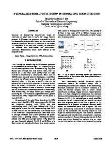
Abstract A voltage scale, Vs that characterizes electro-thermal runaway, is deduced from the heat conduction equation, Vs / 0 , where is the thermal conductivity and 0 is the rate of change of the electrical conductivity with respect to temperature. Vs depends only on material properties and is independent of geometry and the operating voltage. Vs measures the intrinsic tolerance of the material to electro-thermal instability. Numerical values of Vs are consistent with the well-known properties of several common materials. Figure 1. Electro-thermal runaway: a positive feedback.
I. INTRODUCTION It has been estimated that contact problems account for approximately 40 percent of all electrical/electronic failures [1]. Severe heating due to local current constrictions at thin film contacts [2-4] and at bulk contacts [3,5] is also a concern in high power microwave sources, pulsed power systems, field emitters, thin film devices, integrated circuits, and interconnects. In this paper, we investigate one aspect of electro-thermal instabilities, namely, the increase in electrical conductivity as the temperature increases, as is typical of semiconductors. This may lead to thermal runaway, at a fixed voltage, as illustrated in Fig. 1.
II. VOLTAGE SCALE FOR ELECTROTHERMAL RUNAWAY Consider the heat conduction equation,
C
T 2T J E , t
(1)
where C is the heat capacity, is the thermal conductivity, T is the temperature relative to some base value, J is the current density, and E is the electric field. In Eq. (1), the first term on the RHS is the heat diffusion term, and the second term is the heat source term due to ohmic heating. Assume that electrical conductivity σ(T) increases as temperature T increases. By Taylor expansion and ignoring 2nd and higher orders, we have
(T ) 0 0T ,
where σ0 is the initial conductivity of the material, and 0 is the rate of change of the electrical conductivity with respect to temperature. By using Eq. (2), the heat source term in Eq. (1) becomes,
J E (T ) E 2 ( 0 0T ) E 2 ,
(3)
Inserting Eq. (3) into Eq. (1), we have,
C
(2)
T 2T ( 0 0T ) E 2 . t
(4)
Work supported by an AFOSR grant on the Basic Physics of Distributed Plasma Discharges, AFOSR grant FA955009-1-0662, and L-3 Communications Electron Device Division. a
[email protected]
978-1-4673-5168-3/13/$31.00 ©2013 IEEE
Taking the Fourier transform of Equation (4), T ~ e jk x ,
we have, with k k ,
T sT 2 0 E 2 (k ) , C t
(5)
where (k ) is the delta function and
s
0 E k 2
C
IV.
,
E kVs
(6)
(7)
where Vs is the voltage scale which depends only on material properties,
0
.
(8)
Note that Vs is independent of geometry, the operating voltage, and the heat capacity. It measures the intrinsic tolerance of the material to electro-thermal instability. Values of , 0 and Vs are summarized in Table 1 for some common materials. We conclude that SiC is the most resistant to thermal runaway for the same geometry and the same operating voltage, consistent with the wellknown property of this material. Table 1. Voltage scale for electro-thermal runaway. Vs κ σ0’ [Volt] [W/(m-K)] [1/(Ω-m-K)] [10-13] [6-9] Si 142 0.0012-0.7 14.2-348.9 Ge 58 0.0001-0.05 34-761.6 -4 872.9C 127 1.67×10 3903.8 (graphite) 8.33×10⁻⁶ SiC 370 4×10⁻⁷ or 3×10⁴ negative
III.
REFERENCES
2
It follows that T grows exponentially with time if
Vs
scale Vs are consistent with the well-known properties of several common materials. It is important to note that our formulation is quite general and may be applied to other materials, as long as proper approximations in Eq. (2) for the temperature dependent electrical conductivity are used.
SUMMARY
A voltage scale Vs is deduced from the heat conduction equation to characterize electro-thermal runaway. It depends only on material properties and is independent of geometry or the operating voltage. It measures the intrinsic tolerance of the material to electro-thermal instability. Our results based on the calculated voltage
[1] P. G. Slade, ed., Electrical Contacts: Principles and Applications, New York: Marcel Dekker, 1999; P. Stratton, private communications; Review of Federal Programs for Wire System Safety, National Science and Technology Council Final Report, 2000; J. S. Kuzniar and G. A. Slenski, “Wire Integrity Field Survey of USAF Legacy Aircraft”, Defense Technical Information Center, ADP014075, 2001. [2] P. Zhang, Y. Y. Lau, and R. S. Timsit, “On the Spreading Resistance of Thin-Film Contacts”, IEEE Trans. Electron Devices, vol. 59, pp. 1936 – 1940, 2012. [3] P. Zhang, “Effects of Surface Roughness on Electrical Contact, RF Heating and Field Enhancement”, doctoral dissertation, University of Michigan, Ann Arbor (2012). [4] P. Zhang, D. Hung, and Y. Y. Lau, “Current flow in a 3-terminal thin film contact with dissimilar materials and general geometric aspect ratios”, J. Phys. D: Appl. Phys., vol. 46, p. 065502, 2013; Corrigendum, ibid, vol. 46, p. 209501 (2013). [5] P. Zhang and Y. Y. Lau, “Constriction resistance and current crowding in vertical thin film contact”, IEEE J. Electron Dev. Soc., in the press, 2013. [6] mtixtl.com/xtlflyers/SiC.doc [7]http://www.ioffe.ru/SVA/NSM/Semicond/Si/thermal.ht ml [8]http://www.ioffe.ru/SVA/NSM/Semicond/Ge/thermal. html [9] http://www.jyi.org/issue/thermal-conductivitymeasurements-of-graphite-samples/ [10]http://library.thinkquest.org/10784/tempcoeffs_resisti vity.html [11]http://hyperphysics.phyastr.gsu.edu/hbase/Tables/rstiv.html#c1 [12]http://www.microwaves101.com/encyclopedia/silicon carbide.cfm [13]http://cdn.intechopen.com/pdfs/21151/InTechRecent_developments_on_silicon_carbide_thin_films_for _piezoresistive_sensors_applications.pdf