Information and Software Technology 47 (2005) 497–509 www.elsevier.com/locate/infsof
Automatic implementation of constraints in component based applications* Antonio Coronatoa, Antonio d’Aciernob,*, Giuseppe De Pietroc a
DRR-CNR, Via P. Castellino, 111, 80131 Napoli, Italy b ISA-CNR, Via Roma, 52, 83100 Avellino, Italy c ICAR-CNR, Via P. Castellino, 111, 80131 Napoli, Italy Received 29 March 2004; revised 28 September 2004; accepted 30 September 2004 Available online 18 November 2004
Abstract Component-based software architectures have become one of the predominant solutions in the software technologies scenario. As well, constraints have been assuming an ever more relevant role in modeling distributed systems as long as business rules implementation, designby-contract practice, and fault-tolerance requirements are concerned. Nevertheless, component developers are not sufficiently supported by existing tools to implement these features. We address such a deficiency and we propose some implementation patterns to translate constraint models into source code and two automatic tools: the Component Constraint Modeler (CoCoMod) and the Component Constraint Generator (CoCoGen). CoCoMod enables designers to specify both component interfaces and constraints as visual UML models and automatically generates textual models for interfaces and constraints. CoCoGen executes the implementation patters to translate constraint models into source code. A simple case study is presented in order to show an application of the proposed approach. q 2004 Elsevier B.V. All rights reserved. Keywords: Component engineering; Automatic constraints implementation; Component modeling; Development process
1. Motivations In the last decade the nature of software systems has remarkably changed. In particular, the widespread diffusion of computer networks, as well as the constant growth of information systems responsibilities has led to a new way to conceive software systems, no more single, huge, and strongly centralized bundles, but highly distributed architectures. Software distribution has initially been realized by decomposing software systems in modules that implemented specific functions; such highly coupled modules were able to run on distinct computers and adopted the remote procedure call paradigm as communication mechanism. *
We really would like to thank the anonymous referees for their helpful comments and suggestions. * Corresponding author. E-mail addresses:
[email protected] (A. d’Acierno), coronato.a@ inwind.it (A. Coronato),
[email protected] (G. De Pietro). 0950-5849/$ - see front matter q 2004 Elsevier B.V. All rights reserved. doi:10.1016/j.infsof.2004.09.015
More recently software distribution takes place by implementing and releasing cooperating, lowly coupled, software artifacts called components. A (software) component is a software element that can independently be deployed and composed, without modification, to support enterprise business processes [10]. Components, moreover, adhere to the object principle of combining functions and related data into a single unit. A key point for the success of component-based architectures has been the possibility of having easier and more efficient software reuse. The wide diffusion of such architectures has also been pushed up by the emerging of infrastructure middleware technologies like RMI [24], CORBA [23], DCOM [27], and, more recently, Web Services [9], which offer several facilities for developing and deploying cooperating distributed objects over both homogeneous and heterogeneous platforms. Most modeling activities, on the other hand, are accomplished by using the Unified Modeling Language (UML, [18]), which, over the years, has become a de-facto
498
A. Coronato et al. / Information and Software Technology 47 (2005) 497–509
standard. By defining the fidelity of a model as the measure of the correspondence between the model and the final system [14], it can be stated that UML enables designers to produce low-fidelity models to capture high-level system characteristics in the early design phase, as well as highfidelity models to specify low-level system details in the late design phase. As a consequence, UML is an established tool largely used also in modeling complex component-based systems, for which OMG has defined a specific UML profile [19]. However, as long as, say, CORBA components are concerned, when new software components have to be built, once they have been modeled and described, by using UML, and thus at different levels of detail, developers must model component interfaces as Interface Definition Language (IDL, [25]) interfaces, which are then processed by IDL compilers to produce components skeletons. Unfortunately, such skeletons do not keep any track of inter-component relationships and, what is worse, of constraints, although they have been previously specified in UML diagrams. This happens because IDL compilers process IDL models and not UML ones, but IDL does not provide support for modeling neither relationships nor constraints since it was just devised to model interfaces and it does not (and it does not have to) deal with structural features (differently speaking, there is a semantic gap between IDL and UML). Therefore, we can state that current components skeletons fidelity is quite low, where we define the component skeleton fidelity as the measure of how close a component skeleton is to the final component implementation. It is also worth to note that constraints1 have been assuming an ever relevant role in developing new software artifacts. Indeed, the design-by-contract (DBC, [1,28]) practice relies just on the use of some formal constraints for modeling and developing new software systems. This practice has recently been adopted to model component based architectures by Cheesman and Daniels in their modeling process [16], as well as by the Catalysis method [7]. In addition, constraints enable designers to effectively model enterprise business rules, which are generally defined as statements of business practices and policies, assisting in completing requirements. In particular, they are high level functional requirements, which can formally be specified in the late design phases as constraints [4]. Others examples of applications for constraints are presented in [12,13]. In [13], the authors propose a process for implementing collaborations among distributed components; such process uses constraints to model collaborations. In [12], a technique for isolating faults is presented; this technique requires the insertion of contracts, i.e. constraints, in the source code and faults are isolated into the bundle of executed software 1
Herein we use contract and constraint as synonyms even if, as an anonymous referee suggested, contract is elsewhere considered a narrow term. See Section 7 for further details.
instructions grouped by the last verified contract, and the first violated contract. Given the importance of constraints, the semantic gap between UML and IDL has to be filled up by the programmer that, after having compiled skeletons with an IDL compiler, manually implements constraints starting from what has been defined in the design phase and formalized in the UML diagrams (mainly using OCL, the Object Constraints Language [6]). This of course increases developing time and costs, as well as can increase software faults since manually programming activities are increased; a tool able to translate constraints into code could be the solution. In this work we focus on CORBA platforms proposing two tools able to automatically produce enhanced skeletons that already implement constraints like invariants, preconditions, postconditions, and guards. The paper is organized as follows. After discussing about some related papers and projects (Section 2), in Section 3 we describe the Constraint Description Language (CDL) which we defined by taking into account the specific features of component architectures and our final goal of automatic implementation for constraints. The concerns of Section 4 are the development patterns we defined to translate constraints into source code while, in Section 5, we present two tools: the Component Constraint Modeler (CoCoMod) and the Component Constraint Generator (CoCoGen). CoCoMod is a visual UMLbased tool for modeling interfaces and constraints for components. From UML visual models, CoCoMod generates IDL textual models for interfaces and CDL textual models for constraints. CoCoGen is a constraints generator that processes CDL models and then, by executing implementation patterns, realizes enhanced component skeletons that already implement constraints. Next, in Section 6 we present a case study while Section 7 concludes the paper.
2. Related work Bertrand Meyer developed DBC as part of his Eiffel [2] programming language, the only one (as far as we know) that has native support for assertions (used to express contracts). Regardless of its origin, however, DBC is a valuable technique that can dramatically improve software reliability2 for all programming languages (of course including Java and CCC). With the aim of using DBC with, say, Java as programming language several projects have been developed. An approach worth to be mentioned is the one based on iContract [3,29], a preprocessor for the Java language. 2
We adopt the Meyer’s [1] definition of reliability: reliability is the combination of correctness and robustness or, more prosaically, the absence of bugs.
A. Coronato et al. / Information and Software Technology 47 (2005) 497–509
All iContract directives have to be expressed (using an OCL-based syntax) directly in the Java code and they reside in class and method comments (this clearly ensures complete backwards-compatibility with existing Java code, and it is also possible to directly compile the Java code without the iContract assertions). Supported constraints are pre and postconditions, invariants, quantifiers (exists and for all) and implications. In [11] it is presented jContractor, a pure Java implementation of DBC. In such an approach, contracts are written as methods following a simple naming convention; jContractor then provides runtime contract checking by instrumenting the bytecode of classes that define contracts. Using jContractor, it is possible either to add contract-checking code to class files to be executed later, or it can instrument classes at runtime as they are loaded. All contracts are written in standard Java, and since it is purely library based, it requires no preprocessing or modifications to the JVM. Preconditions, postconditions and invariant are supported. In [30] it is proposed a tool that supports the DBC with pre and postconditions for methods, invariants for classes, check statements (used to state an assertion at any part of the program code of the method body), invariants and variants for loops, the usage of for all and exists expressions to express properties that must be valid for all elements of a finite set of assertions or for one element of this set, and rescue-blocks to secure the integrity of the respective instance in the case of a violated exception (e.g. by closing files or freeing memory). Using the JASS approach, constraints must appear in formal comments and have an introducing keyword, which specifies the kind of the assertion. In the most cases the keyword is followed by a list of boolean expressions which describe the allowed states; the boolean expressions can contain variables and method calls. The JASS precompiler will translate such comments into standard JAVA code. A minor comment on these approaches is that guard conditions are not taken into account while the main problem, in our opinion, is that constraints have to be specified directly into the source code at coding time. Instead, the core idea of this paper is that contracts, to be really and widely useful, have to be formalized at design time and have to be language independent, that is designers do not have to concern about the programming language to be used (or, what is worse, to be chosen). Such requirements become even more important when we have to deal with components distributed over a net. Here we (could) have to deal with heterogeneous systems (different components can be implemented with different programming languages); moreover the used middleware for implementing communications could offer potentialities able to verify complex constraints (the relationship service of CORBA first of all). For such a reason, in a previous paper [15], some of the authors proposed a methodology for modeling business rules as constraints and implementing
499
them in component-based applications. In that case, it has been proposed a preliminary tool for generating constraints in components running over Orbix2000 [20], a well-known commercial CORBA platform. In the following, such an idea is expanded and formalized.
3. The constraint description language The modeling language that we defined to formalize constraints is the Constraint Description Language (CDL). This is basically derived from the standard OCL and slightly adapted to component architecture features. The original idea was to adopt the OCL as is but, from one hand, we experienced that only a subset of OCL expressions can automatically be implemented by generation tools. Indeed, being OCL a declarative language, for some kinds of logical expressions it is really hard to define generic implementation patterns. Moreover, OCL expressions that would require inter-component navigations cannot be verified because inter-component relationships should be implemented by the relationship service [8], which is not yet supported by CORBA platforms. From one another hand, we had to provide support for modeling guard conditions. The current version of OCL [19] does not provide direct support for that, whereas the forthcoming version will take them into account [17]. For this reason, we defined a specific construct for guard conditions. We have also found useful to have mechanisms for specifying state changes or forcing the execution of operations once a condition is satisfied. This facility cannot be supported by OCL that is defined to be a side-effect free language. These considerations have suggested the introduction of a new language, the CDL, which has been thought to be as close as possible to OCL; i.e. CDL syntax is almost the same of OCL one, as well as general properties, but CDL has also been specially devised to provide support for the automatic implementation of constraints in component based applications. CDL (as well as OCL) is a formal language that remains easy to read and write because it does not rely on particularly complex mathematical constructs. It is not a programming language; therefore, it is not possible to write program logic. As OCL, it is a typed language, so that each expression has a type and, to be well formed, a CDL expression must conform to the type conformance rules of the language. Finally, as a specification language, all implementation issues are out of scope and cannot be expressed in CDL, but it enables designers to produce textual models, which can easily be processed by automatic tools to generate source code. A brief description of CDL and OCL keywords is reported in Table 1. The keywords supported by OCL and not supported by CDL indicates the characteristics that cannot be automatically implemented by the current version of the tools described in the following sections.
500
A. Coronato et al. / Information and Software Technology 47 (2005) 497–509
Table 1 CDL keywords and OCL keywords Keyword
Description
context inv pre post guard self execute @pre
The class or the operation for the rule Indicates an invariant condition Indicates a precondition Indicates a postcondition Indicates a guard condition Indicates the current instance of a class Requires the execution of an operation Indicates the previous value of a variable Sets the return value of an operation Sets a component attribute to a specific value Forces a rollback action Implement control structures
result set rollback if,then,else, endif not,and,or,xor implies let def in
Define logic operators
OCL W W W W W W W
CDL W W W W W W W W W W
W
W W
W
W
W W W W
Fig. 2. Modeling preconditions in CDL.
the constraint must hold for the invocation of the operation Fig. 2 shows a precondition that must hold before executing Operation_2; if this is not the case we assume that an exception is raised. 3.3. Modeling postconditions
A precondition specifies a constraint that must be attached to an operation, and denotes that the condition of
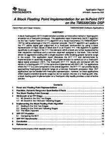
A postcondition specifies a constraint that must be attached to an operation, and denotes that the condition of the constraint must hold after the invocation of the operation. DBC practitioners [16] always couple the postcondition to the precondition. They use them as contracts, the precondition being the contract that the invoking operation must respect, whereas the postcondition is the contract that the invoked operation promises to satisfy after having executed its task. In the case the postcondition is not satisfied, the behavior of the operation is unspecified (i.e. an exception should be raised). Another author [5] suggests to use the postcondition to force the return value of an operation. We believe it could be useful to take into account both interpretations, thus providing support for them. In addition, we extended this concept by also enabling designers to use postconditions for specifying a new state after the execution of the operation. Fig. 3 shows one of these possibilities for a postcondition attached to an operation; the keyword result indicates the return value for Operation_3. It is important to note that both in the case of pre and postconditions, the operation business logic section is partly (sometimes completely) affected. However, the real objective of constraints should be not to specify the method behavior, but to implement business rules, which, just as a consequence, affect the behavior of components’ operations. In any case, designers continue to focus on components’ characteristics and the implementation details are kept hidden by automatic tools.
Fig. 1. An invariant constraint in CDL.
Fig. 3. Modeling postconditions in CDL.
package, endpackage
Used to state implications Defines new entities in a context Defines new entities in a global context Forces an entity to assume values in a specific collection Used to group contexts in packages
W
It is worth to note that constraints are still specified via a declarative approach. This enables designers to model rules by abstracting away from any implementation choice. By this way, designers continue to work without concerning about implementation details. 3.1. Modeling invariant constraints An invariant specifies a constraint that must be attached to a set of attributes or relationships; it indicates that the condition of the constraint must hold over time (the system operates) for the attributes or relationships and their instances As an example, assume that, for a generic component C, an attribute (Attribute_1) must always assume value greater than 0. The CDL syntax used to express such a constraint is shown in Fig. 1. 3.2. Modeling preconditions
A. Coronato et al. / Information and Software Technology 47 (2005) 497–509
Fig. 4. Modeling guards in CDL.
3.4. Modeling guard conditions A guard is a boolean predicate that provides a fine-grained control over the firing of a state transition or an event dispatch. It must be true for the transition or dispatch to be fired and thus it is evaluated any time a state is changed or the event is dispatched. In Fig. 4 it is reported a simple guard condition whose trigger is an attribute (Attribute_3); in that example, the guard forces the execution of an operation (Operation_1) as soon as Attribute_3 becomes false.
4. Implementation patterns In this section we provide some solutions for implementing the constraint types concerned so far; we provide such solutions as implementation patterns According to [1], we assume that, if a contract is violated, an exception is raised; such an exception clearly has to be properly served using resumption (by putting the component back in a valid state) or using organized panic (by reporting the failure to the caller). We do not further investigate this point, even if different strategies could be used to meet designer’s wishes.3 In the following, the implementation patterns are described with respect to the generic component and its constraints as presented in Section 3. For each constraint type, with respect to an example, we report (i) a static model with the component operations that must be added for implementing and verifying the constraint; (ii) a dynamic model that describes activities performed to satisfy the constraint; and (iii) an implementation example in the case of CCC source code. Fig. 5 shows the implementation pattern for invariant constraints that can be simply described as follows: Constraint Context C INV: (self.Attribute_1O0)
501
depending on the invariant condition whether satisfied or not. † Dynamic model B Modify the set_Attribute_1( ) operation in order to invoke the Inv( ) operation to verify the invariant condition. B Also modify the set_Attribute_1( ) operation as follows: Case of condition verified: update the attribute value; Case of condition not verified: do not update the attribute value and rise an exception. Clearly here we have decided to verify the class invariant as soon as the attribute is changed by using the corresponding method. Implicitly, we have assumed that (i) each attribute involved in invariants are private; and (ii) other methods of the class change the attribute again using the appropriate set method. While we think there is no way of implementing invariants on public attributes, the invariant could be checked after each method call. Since an invariant condition clearly could affect more than one attribute, the Inv( ) operation (in that case) must still be implemented, but it must be invoked any time one of the attributes involved in the condition is updated. For preconditions (Fig. 6), we have: Constraint ContextCT Operation_2( ) PRE: ((self.Attribute_3ZZtrue) and (self.Attribute_2 O0)) † Static model B Add the Pre_Operation_2( ) method. This operation must verify the precondition and returns a boolean value depending on whether the condition is satisfied or not. † Dynamic model B Modify the Operation_2( ) operation. This must invoke the Pre_Operation_2( ) operation to verify the precondition. B Also modify the Operation_2( ) operation as follows: Case of condition verified: execute the operation; Case of condition not verified: do not execute the operation and rise an exception. For a postcondition, a case with a set operation is first presented. In this case: Constraint Context CT Operation_3( ) POST: if (self.Attribute_2O0) set Attribute_1Z0
† Static model B Add the Inv( ) method. This operation must verify the invariant condition returning a boolean value 3
Eiffel [2] uses a compilation option to meet programmer’s wishes.
the actions to be performed are: † Static model B Add the Post_Operation_3( ) method. This operation must verify the postcondition. It returns a boolean
502
A. Coronato et al. / Information and Software Technology 47 (2005) 497–509
Fig. 5. The implementation pattern for an invariant: the static model (a), the dynamic model (b) and an implementation example in CCC (c).
Fig. 6. The implementation pattern for a precondition: the static model (a), the dynamic model (b) and an implementation example in CCC (c).
A. Coronato et al. / Information and Software Technology 47 (2005) 497–509
value depending on the condition whether satisfied or not. † Dynamic model B Modify the Operation_3( ) operation. After having performed its task, this operation must invoke the Post_Operation_3( ) operation to verify the postcondition. B Also modify the Operation_3( ) operation as follows: Case of condition verified: set the attribute; Case of condition not verified: rise an exception. Fig. 7 shows the case of postcondition with rollback, a partially implemented functionality. In particular, the rollback is supported in the case no concurrent accesses are allowed to the component. A rollback activity, in the case of concurrent accesses, should rely on the transaction service [26]. Since this CORBA service is not supported in most CORBA platforms, we do not provide yet this facility. Constraint Context CT Operation_3( ) POST: if(not(self.Attribute_2O0)) rollback
† Static model B Add the Post_Operation_3( ) method. This operation must verify the postcondition. It returns a boolean value depending on the condition whether satisfied or not.
503
† Dynamic model B Modify the Operation_3( ) operation to save the current state before executing the operation (by using, say, a provided copy constructor or something else). B Also modify the Operation_3( ) operation so that, after having performed its task, it invokes the Post_Operation_3( ) operation to verify the postcondition. B Last, modify the Operation_3( ) operation as follows: Case of condition verified: return; Case of condition not verified: rollback and rise an exception. Last, we describe the implementation pattern for Guards (Fig. 8): Constraint Context C GUARD: if(self.Attribute_3ZZfalse) self.Operation_1( )
execute
† Static model B Add the Guard( ) method. This operation must verify the guard condition. It returns a boolean value depending on the condition whether satisfied or not. † Dynamic model B Modify the set_Attribute_3( ) operation. After having updated to the new value, this operation must invoke the Guard( ) operation.
Fig. 7. The implementation pattern for a postcondition: the static model (a), the dynamic model (b) and an implementation example in CCC (c).
504
A. Coronato et al. / Information and Software Technology 47 (2005) 497–509
Fig. 8. The implementation pattern for a guard: the static model (a), the dynamic model (b) and an implementation example in CCC (c).
B
The Guard( ) operation behaves as follows: Case of condition verified: invoke Operation_1( ); Case of condition not verified: return.
The guard condition may be related to a complex state by affecting more than one attribute. In that case, any attribute involved in the guard condition acts as a trigger. Therefore, the Guard( ) operation must be executed any time one of these attributes is updated.
5. The supporting tools In the following subsections we describe the tools we propose to support the automatic implementation of constraints in component-based applications. 5.1. The component constraint generator CoCoGen is a generation tool that processes CDL models and then enhances the skeletons of components generated by a regular IDL compiler. The tool is dependent of the target platform, i.e. a specific CORBA platform needs a specific constraint generator, as well as a specific IDL compiler. Currently, the supported platforms are CORBA TAO [22], which is an open project from the Washington University, and Java CORBA ORB [21], which is a free CORBA compliant platform distributed with the J2SE environment.
The tool architecture is shown in Fig. 9. It consists of the following main elements: † Coordinator. This is the main thread that coordinates the processing phases; † Parser. This module is in charge of analyzing CDL models and generating constraints data structures; † Processor. This component implements constraints in the target component skeleton; † Scheduler. This module coordinates the implementation of constraints, which could need proper nesting operations in the component skeletons. It is worth to note that the Processor is the only component which is platform specific. In other words, each CORBA implementation platform requires a specific Processor component. In the current implementation, CoCoGen clearly has two Processor components, one for the TAO platform, the other one for the Java CORBA platform. CoCoGen operates in two phases. During the first phase, the Parser analyzes the input IDL and CDL models and then builds some data structures to be used in the second phase where the Scheduler drives the Implementer in order to implement the constraints. In particular, the Scheduler pops a constraint from data structures, and then requires an implementation to the Implementer. The Implementer executes a specific implementation pattern depending on the constraint type and updates the target component skeleton.
A. Coronato et al. / Information and Software Technology 47 (2005) 497–509
505
Fig. 9. The software architecture of CoCoGen.
5.2. The component constraint modeler CoCoMod is the tool we developed for modeling component interfaces and constraints. It consists of a graphical environment that enables designers to produce UML-based models. From these models, the tool generates both IDL interface models and CDL constraint models. These models are platform independent. After that, from this tool, developers can invoke the execution of CoCoGen to automatically produce enhanced component skeletons for specific CORBA platforms. In Fig. 10 the tools functionalities are shown. IDL models and CDL models generated by CoCoMod are platform independent. Successively, such models are processed by the CoCoGen tool to implement components for the JavaORB platform. In the case of CORBA TAO platform, the difference simply consists in the use of the TAO_IDL compiler instead of the IDLJ one.
and pictures, is associated to each relic. Relics are also periodically verified in order to establish whether to restore them or not. Verifications, as well as restorations, are performed in specialized laboratories. Any time a relic is restored or verified, a verification timeout is set to establish how long to wait before having the next verification. Such a timeout must always range between maximum and minimum values (suppose 6 months and 24 months, respectively) established for relics classes by some generic criteria. Museums can lend/borrow relics to/from other museums in order to organize special events. Relics can be lent only if they are available (not on verification/restoration). Likewise, relics can be verified/restored only if the verification timeout is expired and they have not been lent (they are currently available). In the following, the development activities are described.
6. A simple case study This section presents a simple case study in order to show an application of the proposed approach. We focus on a system that must offer cataloging and exposing functions for relics owned by a museum. Relics are classified by age, epoch, style, and type. A cataloging card, which includes technical descriptions
Fig. 10. High level architecture of the system.
506
A. Coronato et al. / Information and Software Technology 47 (2005) 497–509
6.1. Modeling with CoCoMod First of all, we modeled the system to be realized with CoCoMod There are three components that have been designed (namely Relic, Museum and CatalogingCard). Relic is the component containing relic objects, which are owned by a museum (in turn the Museum component). CatalogingCard stores information about the associated relic. In addition, operations like verification, restoration, and others, are registered in the CatalogingCard. It has also been supposed to have a background procedure that periodically checks the verification timeouts and sets the ToVerify attribute when the timeout has expired. The verification timeout is implemented by the next_verification attribute, which memorizes the number of months to wait for the next verification. Thus, we can assume the following business rules and constraints: † Business Rule 1. Each relic must be periodically verified. B Constraint 1.1. Before having the next verification, one must wait for at least 6 months and no more than 24 months. B Constraint 1.2. A verification can be performed only if the relic is available. † Business Rule 2. Relics can be lent to other museums. B Constraint 2.1. A relic can be lent only if available. We have thus inserted a guard condition that executes the verify operation any time the executing condition gets true for the first business rule. Rule 2 affects the lend method, which can be executed only if the relic is available. Moreover, the lend operation must set the relic state to LENT. Similar constraints must hold for restore and take_back operations. In addition, an invariant constraint has been set over the next_verification attribute in order to assure correct updates.
From such a model, CoCoMod has generated the following IDL model: module CaseStudy { struct Date { short day; short month; short year; }; interface CatalogingCard { attribute long cardID; attribute string description; attribute string picture; attribute boolean toVerify; attribute string relicState; attribute long nextVerification; attribute long lastVerification; void verify( ); void restore( ); void lend( ); void takeBack( ); void showCard( ); }; interface Museum { attribute string name; attribute string address; attribute string city; void planEvent( ); void addRelic( ); }; interface Relic { attribute string name; attribute string type; attribute string style; attribute long age; }; }; and the following CDL file expressing constraints:
package CaseStudy; context CatalogingCardTverify( ): void post: set self.relicState Z “verified” context CatalogingCardTverify( ): void pre: ((self.relicState ZZ “available”) and (self.toVerify ZZ true)) context CatalogingCardTrestore( ): void post: set self.relicState Z “restoring” context CatalogingCardTrestore( ): void pre: (self.relicState ZZ “available”) context CatalogingCardTlend( ): void post: set self.relicState Z “lent”
A. Coronato et al. / Information and Software Technology 47 (2005) 497–509
507
context CatalogingCardTlend( ): void pre: (self.relicState ZZ “available”) context CatalogingCardTtakeBack( ): void post: set self.relicState Z “available” context CatalogingCardTtakeBack( ): void pre: (self.relicState ZZ “lent”) context CatalogingCard inv: ((self.nextVerification OZ6) and (self.nextVerification !Z24)) context CatalogingCard guard: if((self.toVerify ZZ true) and (self.relicState ZZ “available”)) then execute self.verify( ) endif endpackage; From this point on, we will focus only on the CatalogingCard component, which is the one affected by constraints.
platform. As a consequence, the IDL compiler is the TAO IDL tool. 6.3. Generating component constraints with CoCoGen
6.2. Compiling IDL interfaces This activity realizes preliminary skeletons of components In this case, we chose TAO as the target
With this activity, the generated component skeletons are modified by the CoCoGen tool Consider constraint 1.1 that represents a invariant on the next_verification attribute. The TAO IDL compiler produced:
void CaseStudy_CatalogingCard_iT nextVerification(CORBATLong nextVerification) ACE_THROW_SPEC((CORBATSystemException)) { // Add your implementation here } while the same piece of code has been enhanced by CoCoGen as follows: bool CaseStudy_CatalogingCard_iT inv_nextVerification(CORBATLong nextVerification) { if ((nextVerification OZ6) && (nextVerification !Z24)) return true; else return false; } void CaseStudy_CatalogingCard_iT nextVerification (CORBATLong nextVerification) ACE_THROW_SPEC((CORBATSystemException)) { if (inv_nextVerification(nextVerification)) { // Add your implementation here } else throw Exception(“INV DOES NOT HOLD”); } Constraint 1.2 is a precondition on the verify ( )method; TAO IDL produced: void CaseStudy_CatalogingCard_iTverify( ) ACE_THROW_SPEC((CORBATSystemException)) { // Add your implementation here }
508
A. Coronato et al. / Information and Software Technology 47 (2005) 497–509
while the enhanced code is: bool CaseStudy_CatalogingCard_iTpre_verify ( ) { if ((this.relicState,”available”) && (this.toVerify ZZ true)) return true; else return false; } void CaseStudy_CatalogingCard_iTverify ( ) ACE_THROW_SPEC ((CORBATSystemException)) { if (pre_verify ( )) { // Add your implementation here } else throw Exception(“PRE DOES NOT HOLD”); } Last we show the automatic implementation of the guard; since the condition affects two attributes, CoCoGen modified as follows the corresponding set methods: void CaseStudy_CatalogingCard_iT relicState(const char *relicState) ACE_THROW_SPEC((CORBATSystemException)) { // Add your implementation here guard1( ); } void CaseStudy_CatalogingCard_iT toVerify (CORBATBoolean toVerify) ACE_THROW_SPEC((CORBATSystemException)) { // Add your implementation here guard1( ); } Then, it adds the code implementing the guard: void CaseStudy_CatalogingCard_iTguard1( ) { if ((this.toVerify ZZ true) && (this.relicState ZZ “available”)) { this.verify( ); } }
Source code is thus added according to the development patterns. The skeletons of components so far generated are ready to be filled with the business logic. This activity must be manually performed by programmers, who now do not have to care anymore about the implementation of constraints that has been performed by CoCoGen. 7. Conclusions Constraints can no more be neglected while modeling and building component applications. We can also state
that current components skeletons fidelity is quite low, where we define the component skeleton fidelity as the measure of how close a component skeleton is to the final component implementation. The possibility of having automatic tools able to produce component skeletons with an higher degree of fidelity would have valuable effects in terms of development time, development costs, software correctness, and so on. One way to improve the component skeleton fidelity is given by providing tools for automatically implementing component constraints.
A. Coronato et al. / Information and Software Technology 47 (2005) 497–509
In this paper we proposed CoCoGen, a tool for automatically generating constraints-related code; with such an aim, we introduced CDL, a well suited OCL based language for declaring constraints, and we formalized implementation patterns for invariants, preconditions, postconditions and guards. Our tool has been integrated in an UML compliant visual environment (CoCoMod) that we built to enable designers to visually define components interfaces and constraints and to generate (for two major CORBA platforms) skeletons that already implement constraints. Our approach differs from previous ones for the following reasons. The main difference is that we consider constraints under the responsibility of the designer and not of the programmer. As IDL files are automatically generated from UML models and as skeletons are automatically generated by IDL compilers, we guess that constraints, formalized in UML models, have to be automatically implemented. Moreover, we do not define any new programming language and our supporting tools generate standard Java code (for the Java CORBA ORB platform) and standard CCC code (for the TAO platform). As a consequence, designers do not have to deal neither with specific languages (as in the case of Eiffel) nor with specific libraries (as in the case, say, of jContractor). Last, all previous approaches are strictly related to the DBC method. Although our approach includes the DBC one, we consider a larger set of constraints with a more general semantic. In particular, and with respect to preand postconditions, our approach extends the basic semantic enabling designers to specify postconditions that set attributes (i. e. the system is forced in a specific state) or to verify conditions (in that case it is possible to rise an exception and/or to rollback the operation). Moreover we support guards, i. e. actions that have to be performed once the system gets a specific state. For these reasons, we prefer (and used) the term constraint instead of contract. Regarding our work in progress, some enhancements are being considered. First, we are extending CoCoMod with a graphic metaphor for modeling constraints, so that CDL will become an internal language and will not be used by software architects and developers. We are also considering other CORBA platforms together with the possibility of extending CoCoGen to other middleware platforms, such as RMI.
References [1] B. Meyer, Applying design by contract, IEEE Computer, October (1992) 40–51.
509
[2] B. Meyer, Object Oriented Software Construction, 2nd ed., Prentice Hall, Englewood Cliffs, NJ, 1997. [3] R. Kramer, iContract—the Java Design by Contract tool, in: Proceedings of International Conference of Object Oriented Language and Systems (TOOLS 26, USA’98), IEEE Computer Society Press, 1998. [4] R.G. Ross, Business Rule Concept, Business Rule Solutions, 1998. [5] J.J. Odell, Advanced Object-Oriented Analysis & Design Using UML, Cambridge University Press, Cambridge, 1998. [6] J. Warmer, A. Kleppe, The Object Constraint Language: Precise Modeling with UML, Addison-Wesley, New York, 1999. [7] D.F. D’Souza, A.C. Wills, Objects, Components, and Framwiorks with UML: The Catalysis Approach, Addison-Wesley, New York, 1999. [8] OMG, Relationship Service Specification version 1.0, April 2000, available at http://www.omg.org [9] W.L. Oellermann, Architecting Web Services, Apress, 2001. [10] G.T. Heineman, W.T. Councill, Component-based Software Engineering, Addison-Wesley, New York, 2001. [11] P. Abercrombie, M. Karaorman, jContractor: Bytecode instrumentation techniques for implementing design by contract in Java, in: Proceedings of Second Workshop on Runtime Verification, RV 02. Copenhagen, Denmark, July (2002) 26. [12] L.C. Briand, Y. Labiche, H. Sun, Investigating the use of analysis contracts to support fault isolation in object oriented code, ACM SIGSOFT Software Engineering Notes, Proceedings of the International Symposium on Software Testing and Analysis 27 (4) (2002) 4. [13] E. Cariu, A. Beugnard, J.M. Jezequel, An Architecture and a Process for Implementing Distributed Collaborations, in: Proceedings of the Sixth International Enterprise Distributed Object Computing conference (EDOC’02), IEEE Computer Society Press, Los Alamitos, CA, 2002. [14] N. Medidovic, D.S. Rosenblum, D.F. Redmiles, J.E. Robbins, Modeling software architectures in the unified modeling language, ACM Transactions on Software Engineering and Methodology 1 (1) (2002) 2–57. [15] A. Coronato, M. Cinquegrani, G. De Pietro, Adding Business Rules and Constraints in Component Based Applications, in: Proceedings of the International Symposium on Distributed Objects and Applications (DOA 2002), Irvive, CA, USA—LNCS 2519, 2002. [16] J. Cheesman, J. Daniels, UML Components—A Simple Process for Specifying Component-Based Software, Addison-Wesley, New York, 2003. [17] OMG, Response to the UML 2.0 OCL RfP (ad/2000-09-03), Revised Submission, Version 1.6, January 6, 2003. [18] OMG, UML Profile for Enterprise Distributed Object Computing Specifications, available at www.omg.org [19] OMG, Unified Modeling Language Specifications, v1.5, chapter 6, available at www.omg.org [20] IONA, ORBIX 2000 Tutorial, available at http://www.iona.com/docs [21] Sun Microsystems, CORBA Technology and the Java2 Platform, Standard Edition, available at http://java.sun.com/j2se/ [22] http://www.cs.wustl.edu/schmidt/TAO.html [23] OMG, Common Object Request Broker Architecture: Core Specification, version 3.0.3, March 2004, available at http://www.omg.org [24] Sun Microsystems, Java tutorial, available at http://java.sun.com/ developer/onlineTraining/ [25] ISO/IEC 14750 standard. [26] OMG, Transaction Service Specification version 1.4, September 2003, available at http://www.omg.org [27] Microsoft DCOM, available at http://msdn.microsoft.com [28] http://www2.inf.ethz.ch/personal/meyer/ [29] http://www.javaworld.com/javaworld/jw-02-2001/jw-0216-cooltools. html [30] http://csd.informatik.uni-oldenburg.de/jass