Cyclic Delay Diversity with Space-Frequency Coding for OFDM Systems Ayon Quayum, Mursalin Habib
M. Nazrul Islam
Fakhrul Alam
Technical Division, GrameenPhone Ltd. Gulshan-2, Dhaka, Bangladesh
[email protected] [email protected]
Dept. of Electrical and Electronic Engineering Bangladesh University of Engineering and Technology, Dhaka-1000, Bangladesh
[email protected]
IIMS, Massey University Private Bag 102 904, NSMC Albany, Auckland, New Zealand
[email protected]
Abstract - Space-Frequency Coding (SFC) is a transmit diversity scheme to achieve full spatial diversity. But it does not exploit frequency selectivity of the channel. Cyclic Delay Diversity (CDD) is a simple technique to increase the frequency selectivity of the cha`nnel experienced by the receiver and thus randomize the error bursts. The increased frequency selectivity can be exploited by using Forward Error Correction (FEC) code to improve performance. In this paper we propose a novel technique to combine SFC with CDD for an Orthogonal Frequency Division Multiplexing (OFDM) system. In the proposed scheme the transmit signal is coded into orthogonal signals for the first n transmitting antennas in frequency domain. Normalized summation of the signals from n antennas is then cyclically shifted in time and transmitted using the next m antennas. We present simulation results to show that for different environment and diversity order different values of n and m will achieve optimum performance.
I.
INTRODUCTION
In recent years Orthogonal Frequency Division Multiplexing (OFDM) based transmission schemes have gained much popularity and are being used in different standards such as IEEE 802.11 [1] for Local Area Network (LAN), IEEE 802.16 [2] for Metropolitan Area Network (MAN) etc. With the widespread use of OFDM systems the demand for better performance is ever increasing. One way to provide better throughput, improved quality and optimum use of bandwidth is to employ spatial diversity techniques [3]. Different diversity techniques have been proposed and investigated for OFDM system in the literature. A comprehensive study on spatial diversity was presented in [3]. Space-Frequency Coding (SFC) was suggested in [4] and was further investigated in [5], [6]. Space-Time Block Coding (STBC) was proposed in [4] and developed for orthogonal design in [7]. Further work was done with Space Time Coding (STC) for OFDM in [8], [9]. Receiver diversity techniques for OFDM system were discussed in [10]. Another kind of diversity termed Delay Diversity (DD) [8] and Cyclic Delay Diversity (CDD) [11] was developed to exploit frequency selectivity of the channel. In [12] CDD was discussed in the context of an OFDM system. A comparison between STBC and CDD was presented in [13] and showed that in most cases STBC outperforms CDD. But the main advantage in CDD remains in its structural simplicity and much lower complexity compared to STBC. In [14] a scheme
was proposed where the signal is cyclically shifted both in frequency domain and in time domain. In this paper we propose a new diversity technique combining SFC and CDD to exploit both spatial diversity and frequency selectivity of the channel at the same time. We use the first n antennas in the transmitter for SFC signals. The next m antennas transmit cyclically delayed signals so that they provide CDD for each of the first n antennas. The rest of the paper is organized as follows. In section II the existing scheme of SFC and CDD are discussed. In section III the new diversity scheme is explained. In section IV we present simulation results to show the performance of the new scheme in different environments. In section V we draw some conclusions. II. SFC AND CDD A. Space Frequency Coding (SFC) SFC is a form of spatial diversity technique where the signals are coded into multiple sets of orthogonal signals in the frequency domain for the transmitting antennas. The signals are then sent simultaneously from the transmit antenna array and superimposed in the receiving antenna. After receiving consecutive signals from channels with different frequency or from the same channel in different time slots they are combined to reconstruct the original signals. SFC can readily be implemented in OFDM system since the signals are transmitted using different sub carriers and originally mapped to construct frequency domain symbols. Different coding schemes can be employed for SFC. Two popular schemes are Space Frequency Trellis Code (SFTC) [15] and Space Frequency Block Code (SFBC) [16]. In [4] a scheme known as Alamouti Scheme is suggested. This is a simplified version of STBC for two transmit antenna system. This scheme can easily be adopted for SFC. In this paper we will use Alamouti scheme for SFC during further discussion. The proposed scheme can easily be extended for SFTC, STBC or any other orthogonal coding scheme without further modification. In Alamouti scheme the two consecutive signals are coded for two transmit antenna. Let the two consecutive signals in frequency domain be X1(k ) and X 2 (k ) . They are coded according to Table1.
TABLE I ALAMOUTI SCHEMES FOR SFC OFDM Symbol Antenna 1
Antenna 2
i Symbol (Subcarrier fC 1 )
X 1 (k )
X 2 (k )
(i + 1) Symbol (Subcarrier fC 1 )
∗ 2
X 1 (k )
th
th
∗
−X (k )
1 m
HCDD ( f ) =
Thus received signals in each subcarrier for two consecutive OFDM symbols form a space frequency code which can be decoded using their weighted sum. In order to calculate the weights we require channel state information which can be estimated with the aid of predefined training sequence. While Alamouti scheme can achieve full spatial diversity it lacks any inherent property to utilize frequency selectivity of the channel. As many existing and proposed OFDM systems experience frequency selective channels (even though the individual sub-carriers experience flat channels) it is imperative that a diversity scheme is able to operate in such an environment. This makes it important to implement other scheme with SFC.
m
∑ H i (f )e
− j 2π f
τi N
.
(3)
i =1
Judiciously selected delays will sufficiently randomize the channel response and redistribute the errors throughout the subcarriers [12]. So the FEC has better chance to correct the errors. Another point to be considered in CDD is how to choose the delays. It was demonstrated in [11] that the optimum delay time at the ith antenna can be found as. τi = (i − 1)
N m
(4)
Where m is the total number of transmit antenna for CDD system and N is the number of sub-carriers while i indicates the index of any single antenna. In this paper we employ Equation 4 for selecting cyclic delays.
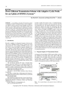
B. Cyclic Delay Diversity (CDD) CDD is a diversity technique that can be used either at the transmitter or the receiver [11]. In CDD the effective portion of OFDM symbols, i.e. without cyclic prefix, are cyclically shifted in time. So the signals from different antenna elements act as virtual echoes of the original signal. This introduces large delay spread in the channel and results in small coherence bandwidth. Consequently the bit errors become more randomized. Fig. 1 shows the error distribution per subcarrier. We can observe that the probability of occurrence of long error burst decreases with CDD. This fact can be well utilized using FEC. As the delays are inserted in time domain they contribute different phase angles in different subcarriers in frequency domain after FFT. So the channel response changes to a more randomized form. For a CDD system with m transmit antenna the total transmitted signal is given by
xCDD (t ) =
1 m
m
∑ x ( t − τi ) .
(1)
i =1
Here x (t ) represents the original signal and τi is the cyclic delay at the ith transmitter antenna. The frequency domain representation of the signal with cyclically delayed OFDM − j 2π f
τ
N where N is the number of symbol is given by X ( f )e FFT point or sub-carrier. For m antenna the total signal in receiver is
YCDD (f ) =
1 m
m
∑ X (f )e
− j 2π f
τi NH
i (f )
+ NT
(2)
i =1
where the channel response is given by H i ( f ) and thermal noise by NT . We can define the modified channel response as
Figure 1: Percentile Error per sub-carrier. Cyclic Delays are 0, 16, 32, and 48. FFT = 64 point. SNR = 8 dB.
III. COMBINING SCHEME FOR SFC AND CDD A. Transmitter The Transmitter is implemented with (n + m ) transmitting antennas. The first n antennas are used for SFC and next m antennas are used for CDD. The transmission scheme is depicted in fig. 2. After the signals are coded and interleaved they are mapped according to the modulation scheme. Then the signals go through space frequency coding process. After SFC, the signal is fed to n IFFT blocks corresponding to n transmit antenna elements. The outputs of the IFFT blocks make up the effective parts of the OFDM symbols. Cyclic Prefix (CP) is added to the OFDM symbols to prevent Inter Symbol Interference (ISI). Then these symbols are used as the inputs for the first n transmit antennas. The transmitted signals form SFC and provide spatial diversity for the system. All signals are normalized to meet the power requirement.
The signals from the n IFFT blocks are summed and copied into m parallel data streams to be used in CDD. Each signal is cyclically delayed by a particular delay time for each antenna. These delayed signals are prefixed by cyclic extensions and transmitted from the next m antennas. Let the orthogonal signals for first n antennas after SFC block be represented by the vector T XSFC ( f ) = ⎡⎢ X1 ( f ) X 2 ( f ) … Xn ( f ) ⎤⎥ . (5) ⎣ ⎦ Here Xi ( f ) represents signals for i th antenna. After IFFT block the signal vector becomes T x SFC ( t ) = ⎡⎢ x1 ( t ) x 2 ( t ) … x n ( t ) ⎤⎥ . (6) ⎣ ⎦ To compose the signals for CDD all the signals from the first n antennas are summed. The summation is then cyclically shifted. So the signal vector for the next m antenna becomes T xCDD ( t ) = ⎡⎢ x∑ ( t − τ1 ) x∑ ( t − τ2 ) … x∑ ( t − τn ) ⎤⎥ (7) ⎣ ⎦ Here x ∑ ( t ) is defined as x ∑ ( t ) = x1 ( t ) + x 2 (t ) + … + x n (t ) (8)
Now the total signals from ( n + m ) antennas are transmitted at the same instant. So they are superimposed. After normalization the total transmitted signal is given by m n ⎡ n ⎤ 1 ⎢ ∑ xi ( t ) + ∑∑ xi (t − τ j ) ⎥ (9) xTotal ( t ) = ⎥ n + mn ⎢⎣ i =1 j =1 i =1 ⎦ m +1 1 xTotal ( t ) = x1 ( t − τk ) + ... m + nm k∑ =1 (10) m +1 1 xn ( t − τk ) ... + m + nm k∑ =1 In (10) τ1 = 0 and represent the signals of first n antennas. Equation (10) shows that the new system can be considered as the summation of n individual CDD systems where each CDD system employs ( m + 1 ) antennas. In (10) the n terms in the summation represent n SFC signals (with cyclically delayed versions) which are orthogonal in frequency domain.
Figure 2: The proposed transmit diversity scheme
B. Receiver The Receiver is relatively simple as only regular decoding of the SFC is needed. The receiver is depicted in Fig. 3. After the removal of the cyclic prefix, the received signal is passed through the FFT block which converts the signal to frequency domain. The pre SFC signal is then retrieved by using SFC
Decoding block which provides data stream. The SFC Decoding block needs channel state information. This can be provided by employing a channel estimation algorithm. Then the signal is de-mapped. After de-mapping the signal is deinterleaved and decoded to retrieve the original data.
Figure 3: The receiver
IV. SIMULATION RESULTS
The simulation is performed according to the system described in section III. For the required SFC in our scheme, we used Alamouti Scheme. In section II the SFC technique was described in detail. For CDD the cyclic delays were chosen according to (4). Other system parameters are described in Table 2. TABLE II SIMULATION PARAMETERS Modulation 16 QAM FFT Length 64 Sampling Rate 40 MHz OFDM Symbol Duration 4 us Training Symbol 12 Detection MMSE Cyclic Prefix 1 us Coding (133, 171), Convolutional Code, ½ Rate Channel fractional power [0.19 0.38 0.24 0.09 0.06 0.04] Channel Path Delay Profile [0.00 0.02 0.05 0.16 0.23 0.50] us Doppler Spread 20 Hz Channel Estimation Perfect
reduces to a simple SFC system. Other two systems show the performance for different values for m . In the second system the value of m is 1 and in third system the value of m is 3. Now each system contains (m + 1) antenna CDD system for each antenna used in SFC. So they effectively have 2 and 4 antenna CDD schemes respectively. Due to this fact the performance for m = 2 is superior compared to that of m = 1. More antenna elements for CDD provide better randomization of error which means more help to the error correction scheme. The performance improves rapidly from m = 0 to m = 1. While the improvement is less as m becomes 2. This is because when m is 0, frequency selectivity of the channel is not utilized. While second and third both systems capitalizes on frequency selectivity of the channel.
Fig. 4 shows a comparison of the proposed technique with Cyclic Delay Diversity (CDD). The proposed scheme outperforms CDD system when the total transmit antenna is 4 in the system. In fig. 4 a system of SFC CDD combining scheme is shown where n=3 and m=1. This system has better performance than the system employing CDD only. The reason is that in SFC CDD combining scheme it is possible to achieve full spatial diversity with three antennas using SFC and utilizing the frequency selectivity of the channel with the fourth antenna.
Figure 5: Effect of change in system parameter m in proposed SFC CDD Combining Scheme. n = 2. m = 0, 1 and 3.
V. CONCLUSION
Figure 4: Comparison with Cyclic Delay Diversity (CDD), ½ rates, 4 antenna with proposed SFC CDD Combining Scheme 4 antenna. n=3, m=1.
Fig. 5 shows the effect of increasing the number of antenna in new diversity scheme. The new combining scheme uses (n + m ) transmit antenna as described in section III. Here n indicates the number of antenna used for SFC and m is the number of antenna used for CDD. In the first system the value of n is 2 and the value of m is zero. So the system
In this paper we proposed a new diversity scheme which combines SFC and CDD. As the CDD system does not need any special decoding, the proposed system need only SFC decoder in the receiver. It can be easily shown that CDD and SFC are two extreme cases of the new combining scheme. When n is zero the system reduces to CDD system and with m is zero the system becomes SFC system. The system is developed for OFDM but the technique can be very easily extended to MC-CDMA or any other multi carrier system. In view of the increase in performance attained by the proposed scheme, it may be worthwhile to further investigate their application for use in multi-carrier systems. REFERENCES [1]
IEEE 802.11-1999, Wireless LAN Medium Access Control (MAC) and Physical Layer (PHY) specifications, 1999.
[2]
[3]
[4]
[5]
[6]
[7]
[8]
[9]
IEEE 802.16-2004, IEEE Standard for Local and metropolitan area networks; Part 16: Air Interface for Fixed Broadband Wireless Access” 2004. Diggavi S. N., Al-Dhahir N., Stamoulis A., and Calderbank A. R., Great expectations: the value of spatial diversity in wireless networks, Proceedings of the IEEE Volume 92, Issue 2, Feb 2004 Page(s):219 - 270 H. Alamouti S. M., A simple transmit diversity technique for wireless communications, Selected Areas in Communications, IEEE Journal on Volume 16, Issue 8, Oct. 1998 Page(s):1451 - 1458 Yi Gong, and Letaief K. B., An efficient space-frequency coded OFDM system for broadband wireless communications, Communications, IEEE Transactions on Volume 51, Issue 12, Dec. 2003 Page(s):2019 – 2029 Lee K. F., and Williams D. B., A space-frequency transmitter diversity technique for OFDM systems, Global Telecommunications Conference, 2000. LOBECOM '00. IEEE Volume 3, 27 Nov.-1 Dec. 2000 Page(s):1473 - 1477 vol.3 Tarokh V., Jafarkhani H., and Calderbank A.R., Space-time block codes from orthogonal designs, Information Theory, IEEE Transactions on Volume 45, Issue 5, July 1999 Page(s):1456 - 1467 Li Y., Chuang J., and Sollenberger N. R., Transmitter diversity for OFDM systems and its impacts on high-rate wireless networks, Communications, 1999. ICC 99. 1999 IEEE International Conference on Volume 1, 6-10 June 1999 Page(s):534 - 538 vol.1 Zhiqiang Liu, Yan Xin, and Giannakis G.B., Space-time-frequency coded OFDM over frequency-selective fading channels, Signal Processing, IEEE Transactions on Volume 50, Issue 10, Oct. 2002 Page(s):2465 – 2476
[10] Sugbong Kang, and Lehnert J.S., Receiver diversity scheme for OFDM systems, Electronics Letters Volume 39, Issue 18, 4 Sept. 2003 Page(s):1359 – 1361 [11] K. Witrisal, Y.H. Kim, R. Prasad & L.P. Ligthart, Antenna Diversity for OFDM using Cyclic Delays, In proc. IEEE 8th Symposium on Communications and Vehicular Technology in the Benelux, SCVT2001, October 2001. [12] A. Huebner, M. Bossert, F. Schuehlein, H. Haas, and E. Costa, On Cyclic Delay Diversity in OFDM Based Transmission Schemes, 7th International OFDM-Workshop (InOWo), Hamburg, Germany, 2002. [13] A. Dammann, R. Raulefs, G. Auer, and G. Bauch, Comparison of space-time block coding and cyclic delay diversity for a broadband mobile radio air interface, In Proceedings 6th International Symposium on Wireless Personal Multimedia Communications (WPMC 2003), Yokosuka, Japan, volume 2, pages 411-415, Oct. 2003 [14] Huebner A., Schuehlein F., Bossert M., Costa E., and Haas H., A simple space-frequency coding scheme with cyclic delay diversity for OFDM, Personal Mobile Communications Conference, 2003. 5th European (Conf. Publ. No. 492) 22-25 April 2003 Page(s):106 – 110 [15] Zihua Guo, Wenwu Zhu, and Letaief K.B., Space-frequency trellis coding for MIMO OFDM systems, Vehicular Technology Conference, 2003. VTC 2003-Spring. The 57th IEEE Semi annual Volume 1, 2225 April 2003 Page(s):557 - 561 vol.1 [16] Dehghani M. J., Aravind R., Jam S., and Prabhu M. M., Spacefrequency block coding in OFDM systems, TENCON 2004. 2004 IEEE Region 10 Conference Volume A, 21-24 Nov. 2004 Page(s):543 – 546