Cat C1.1 Diesel Engine Service and Workshop Manual Displacement 1.13 L (69.0 in3) Compression Ratio: 23:1 *
CYLINDER HEAD
ENGINE
Unit Part
Unit for values without unit in the column of inspection item is mm.
Standard Dimension
Inspection Items
Standard Value
To be Repaired
Compression pressure of cylinder MPa (kgf/cm2)
More than 2.94 (More than 30)
Less than 2.45 (Less than 25)
Distortion of face of cylinder head
Less than 0.05
More than 0.12
0.85 – 1.15
1.8
1.7 – 2.1
More than 2.5
Width of valve seat (intake/exhaust)
CYLINDER BLOCK
Distortion of upper face of cylinder block
PISTON
∅77
Clearance to cylinder Inside diameter of piston pin hole
∅21
Piston pin hole-to-pin clearance PISTON PIN
Remarks Engine 200 rpm
Valve sheet angle 45°
∅21
Outer diameter of pin Small end bush-to-pin clearance Piston ring gap:
Piston ring groove-to-ring clearance
∅77.99 – 77.005
∅77.2
Less than 0.05
0.12
0.25
∅20.998 – 21.002
21.016
-0.004 - +0.004
0.02
∅20.998 – 21.002
∅20.98
0.008 – 0.023
0.08
No.2 ring
0.12 – 0.24
Oil ring
0.2 – 0.35
No.1 ring
0.06 – 0.1
No.2 ring
0.05 – 0.09 0.02 – 0.06
No.1 ring
2
1.97 – 1.99
No.2 ring
1.5
1.47 – 1.49
4
3.97 – 3.99
Heavy Equipment Restoration Parts LLC Phone: 269 673 1638 email:
[email protected]
Oversize Piston 0.50 MM
∅0.0525 – 0.0865
0.15 – 0.27
Oil ring
Over size (0.5)
∅77.9225 – 77.9375
No.1 ring
Oil ring Ring width
Coat threads with molybdenum bisulfulde based grease.
49 ~ 52 (5.0 – 5.3)
∅77
Bore
Skirt diameter (longer diameter)
PISTON RING
Allowable Limit
T220
Tightening torque of cylinder head N⋅m (kgf⋅m)
MAIN MOVING SYSTEM
Indirect Injected
At 20°C
Oil clearance
1.0
0.25 0.15 Oversize Piston Rings 0.50 MM
Cat C1.1 Diesel Engine Service and Workshop Manual Part
Standard Dimension
Inspection Items
Allowable Limit
Standard Value
To be Repaired
Twist between small and large end holes (per 100 mm)
Less than 0.08
More than 0.2
Straightness at 100 mm between small and large end hole
Less than 0.05
More than 0.15
Front-to-rear clearance between connecting rod and crank pin
0.1 – 0.3
0.7
0.035 – 0.083
0.2
Connecting rod metal-to-crank pin clearance Connecting rod bearing (inner diameter × width)
Remarks
Oil clearance
∅37 × 17.5
Connecting rod bolt torque
29 ~ 34 (3.0 – 3.5)
N⋅m (kgf⋅m)
Weight difference with piston
(g)
Less than 10
Crush height of small end bush
0.034 – 0.079
Diameter of main journal
∅47.964 – 47.965
Diameter of crank pin
∅40.964 – 40.975
Roughness, main journal and crank pin
Under size (0.25, 0.50)
Under size (0.25, 0.5)
1.6Z
Crankshaft deflection
CRANKSHAFT
MAIN MOVING SYSTEM
CONNECTING ROD
Unit
Less than 0.03
Axial play of crankshaft No.4 bearing holder thickness
More than 0.06
0.05 – 0.3
0.5
21.85 – 21.95
21.55 Under size (0.25, 0.5)
∅47.964 – 47.965
Diameter of bush (journal metal) Clearance between crankshaft and journal metal (bush)
0.039 – 0.106
0.2
Oil clearance Under size (0.25, 0.5)
CAMSHAFT
0.2
Oil clearance Upper No. 2 and 3.
0.029 – 0.082
0.2
Oil clearance Lower No.4
For intake/exhaust
26.565 – 26.62
26.2
For injection pump
33.94 – 34.06
33.8
T221 Backlash of cam gear
VALVE
VALVE SYSTEM
Clearance between crankshaft journal and center bearing
0.039 – 0.092
0.08
0.25
Diameter of intake valve stem
6.955 – 6.97
6.89
Diameter of exhaust valve stem
6.94 – 6.955
6.84
0.03 – 0.06
More than 0.2
0.045 – 0.075
More than 0.25
0.775 – 1.075
0.5
Clearance between valve stem and valve guide
Inlet Exhaust
1.0 T222
Cat C1.1 Diesel Engine Service and Workshop Manual Unit Part
Standard Dimension
Inspection Items Valve clearance (Intake/exhaust)
VALVE
VALVE SYSTEM
Spring strength
Valve spring
Inlet valve timing
PUSH ROD ROCKER ARM
Open-Before T.D.C
13°
Close-After B.D.C.
43°
Open-Before B.D.C.
43°
Close-After T.D.C.
13°
Overall length
157
Outer diameter
∅6.3 ∅11.66
Wear, rocker arm shaft Clearance between rocker arm and shaft
OIL PUMP
Oil pressure switch operating pressure kPa (kgf/cm2)
INJECTION PUMP
LUBRICATION SYSTEM
Free height
To be Repaired
0.2
0.5
Allowable Limit
Remarks When cooling temperature
8.1
Less than 7
35
33.5
Less than 1.2
2.0
At 30.4 mm compressed length
T223
Exhaust valve timing
FUEL SYSTEM
(kgf)
Standard Value
29.4 (0.3)
Lubrication oil capacity
(ℓ)
∅11.65 – 11.668
∅11.57
0.032 – 0.068
0.2
19.6 – 39.2 (0.2 – 0.4)
With filter change 3.3 ℓ
3.0
Tip clearance (rotor-to-vane)
0.1 – 0.15
0.25
Side clearance (rotor-to-cover)
0.1 – 0.15
0.2
Type
094500-6340
Injection timing
Before T.D.C. Piston movement before T.D.C.
Oil clearance
245 – 343 (2.5 – 3.5)
kPa (kgf/cm2)
Relief pressure
156.8 – 157.2
DENSO
23 - 25° 4.217 – 4.96
Heavy Equipment Restoration Parts LLC Phone: 269 673 1638 email:
[email protected]
Cat C1.1 Diesel Engine Service and Workshop Manual
COOLING
COOLING SYSTEM
INJECTION NOZZLE
Unit Part
Inspection Items
Standard Dimension
Standard Value
11.76 (120)
11.27 – 12.25 (115 – 125)
Type Injection pressure
MPa (kgf/cm2)
Angle of injection direction Cooling method
kgf/cm
Coolant capacity
(ℓ)
3.5
(°C)
82
Thermostat full-open temperature (°C)
95
Thermostat open temperature
DENSO
Water colded, forced circulation
80 – 84
M30 128000 – 0101
No. of teeth of pinion gear STARTER MOTOR
Remarks
4° 2
V belt
Shifting method of pinion
Magnetic shift type
Wear of commutator diameter
30
29
Stepped wear of commutator
0.05
Bending allowance of armature shaft
0.05
Spring force of brush
DENSO
9
Length of brush
ALTER MATOR
Allowable Limit
093500 – 3320
Type
ELECTRICAL SYSTEM
To be Repaired
N (kgf)
Type
0.2 More than 0.08
13.5
9
16.7 (1.7)
Less than 11.76 (1.2) 100211 – 1680
DENSO
Outside diameter of slip ring
14.4
14.0
Length of brush
10.5
4.5
Pulley tightening torque N⋅m (kgf⋅m)
Heavy Equipment Restoration Parts LLC Phone: 269 673 1638 email:
[email protected]
58.3 – 78.8 (5.95 – 8.05)
Cat C1.1 Diesel Engine Service and Workshop Manual
2-3
Disassembly, Inspection and Reassembly
1. DISASSEMBLY
T102
Disassembly Order
Parts Name
1
Alternator
2
Starting motor
3
Oil filter
4
Relief valve
5
Oil level gauge · Gauge guide
6
Engine stop solenoid · Seal washer
7
Injection pipe
8
Injection pump NOTE: 1. Remove the injection pipes and engine stop solenoid before remove the injection pump. 2. Raise the injection pump and remove the governor link from the control rack. 3. Injection timing has been adjusted by the shims between injection pump and cylinder block. Take note of their thickness and number when removing the injection pump.
Cat C1.1 Diesel Engine Service and Workshop Manual
T103
Order
Parts Name
9
Return pipe
10
Injection nozzle · gasket
11
Oil pipe · Eye bolt · Seal washer
12
Glow plug · Connector
13
Thermo-sensor
14
Oil pressure switch
15
Head cover
16
Rocker arm assembly NOTE: Draw out the roll pin (A) from the No. 1 rocker arm bracket, and remove the rocker arm shaft.
17
Push rod
18
Cylinder head · Head gasket NOTE: 1. If necessary, remove the intake valves and exhaust valves with covered shop towel for prevent jump out the parts by spring.
19
Tappet NOTE: Store carefully to ensure they are refitted to the same place.
Cat C1.1 Diesel Engine Service and Workshop Manual
T104
Order
Parts Name
20
Fan holder · Fan pulley · V-belt · Cooling fan
21
Water pump assembly · Thermostat · Gasket
22
Hydraulic oil pump · Power steering oil pump
23
Crankshaft pulley
24
Timing gear case assembly NOTE: Remove the engine stop solenoid and injection pump assembly at first.
25
Idle gear · Oil pump assembly
26
Cam shaft assembly · Tachometer assembly NOTE: Remove the bolts and plate at first, and remove the cam shaft assembly and tachometer assembly.
27
Front plate · Gasket
Heavy Equipment Restoration Parts LLC Phone: 269 673 1638 email:
[email protected]
Cat C1.1 Diesel Engine Service and Workshop Manual
T105
Order
Parts Name
28
Oil pan · Gasket · Suction filter · Suction pipe
29
Fly wheel
30
Rear plate
31
Oil seal
32
Piston and connecting rod assembly NOTE: 1. Before extracting piston, remove the carbon deposit from the TDC in the cylinder. 2. Place the connecting rod, cap and bearing removed in order of the cylinders.
33
Crank shaft and bearing holder assembly NOTE: Remove the four bolts, and draw out the crank shaft and bearing holder assembly as a set.
Heavy Equipment Restoration Parts LLC Phone: 269 673 1638 email:
[email protected]
Cat C1.1 Diesel Engine Service and Workshop Manual 2.
DISASSEMBLY AND INSPECTION OF ENGINE MAIN PARTS * Cautions before start 1) 2) 3) 4)
Check the cylinder block and cylinder head for wear, leakage and damage. Remove deposit in oil holes of each part with air and check for clogging. Wash each part well to remove dust, contaminated oil, carbon, and other foreign matter. Remove carbon deposite on the piston, cylinder head, valves, etc. carefully not to damage parts. (Great care is necessary specifically for aluminum alloy parts.) 5) Valves, pistons, connecting rods, metals and other parts which are to be combined as specified should be attached match marks beforehand to prevent confusion.
1) Rocker arm ass’y Disassembly (1) Remove the bolts at both ends of the rocker arm shaft and take out the rocker arm, rocker arm bracket, spring and shim. (2) Extract the spring pin which has been driven into the No. 1 cylinder rocker arm bracket and take out the rocker arm, spring and bracket. 1. Rocker arm bracket 2. Rocker arm
T106
Inspection and service (1) Using a micrometer, check outside diameter of the rocker arm shaft. If the shaft is worn exceeding service limit, replace it with new one. Wear of rocker arm shaft ø Standard assembling value
Service limit
11.65 – 11.668
Less than 11.57
T107
(2) Measure the inside diameter of the rocker arm. Calculate the clearance between the rocker arm and rocker arm shaft. If the clearance is excessive, replace the part. Clearance between rocker arm and rocker arm shaft (mm) Standard assembling value
Service limit
0.032 – 0.068
More than 0.2
Heavy Equipment Restoration Parts LLC T108 Phone: 269 673 1638 email:
[email protected]
Cat C1.1 Diesel Engine Service and Workshop Manual 2) Cylinder head ass’y Disassembly (1) Using a valve spring replacer, compress the valve spring to remove the valve cotter, retainer, spring and valve. (2) Remove the valve guide seal. 1. Valve guide seal 2. Spring 3. Retainer
4. Valve 5. Valve cotter
T109
Inspection and service (1) Distortion of cylinder head bottom surface Apply a straight edge to the bottom surface of the cylinder head, and insert a thickness gauge at 6 points from A to F in the right figure and measure distortion. If the distortion exceeds the repair value, correct with surface grinder or the like. Distortion at cylinder head bottom surface (mm) Standard assembling value
Repair value
Less than 0.05
More than 0.12
T110
(2) Valve guide and valve stem ➀ Check the head and stem of each valve and replace if burnout, wear or deformation is remarkable.
Wear of valve stem (mm) Intake valve
Exhaust valve
Standard assembling value
Service limit
Standard assembling value
Service limit
6.955 – 6.97
6.89
6.94 – 6.955
6.84
➁ Measure the outside diameter at the position I, II, and III on the valve stem with a micrometer and replace if the result is less than the service limit. T111 ➂ Replace a valve if its head thickness is less than service limit.
Valve head thickness (mm) Standard assembling value
Service limit
0.775 – 1.075
Less than 0.5
Heavy Equipment Restoration Parts LLC Phone: 269 673 1638 email:
[email protected]
T112
Cat C1.1 Diesel Engine Service and Workshop Manual ➃ Replace the valve if the clearance between the stem and guide exceeds the service limit.
Clearance between valve stem and valve guide (mm) Intake valve
Exhaust valve
Standard assembling value
Service limit
Standard assembling value
Service limit
0.03 – 0.06
More than 0.2
0.045 – 0.075
Mora than 0.25
T113 (3) Valve seat ➀ Since the valve seat is corrected according to the valve guide, be sure to check the valve guide for wear condition first before correcting the seat.
Valve seat contact width (mm) Standard assembling value
Repair value
1.7 – 2.1
More than 2.5
➁ Correct the seat to the standard assembling values of the contact width and recess using seat cutters of 15°, 45° and 75°.
T114 Valve seat recess (mm) ➂ When the seat recess exceeds the service limit, replace the cylinder head.
Standard assembling value
Service limit
0.85 – 1.15
More than 1.8
Heavy Equipment Restoration Parts LLC Phone: 269 673 1638 email:
[email protected]
T115
Cat C1.1 Diesel Engine Service and Workshop Manual ➃ Coat the valve seat surface with compound and lap the contact surface turning the valve. ➄ Check that the valve contact surface is within the standard value and the contact position is even. ➅ When the cylinder head is replaced with new one, adjust the seat contact width and seat recess to the specified values with a seat cutter before lapping.
T116
(4) Valve spring ➀ Check the valve spring visually for damage. ➁ Measure the squareness of the spring using a square on a surface plate and replace if the service limit is exceeded. ➂ Check the free length and spring force with a spring tester and replace if the service limit is exceeded.
Standard assembling value
Service limit
Squareness (mm)
1.2
More than 2
Free length (mm)
35
Less than 33.5
72.9 N (8.1 kgf)
68.6 N (Less than 7 kgf)
Spring force (when compressed to 30.4 mm)
(5) Inner face of combustion chamber Pull out the cap and insert from the cylinder head. Check and clean the combustion chamber.
T117
NOTE: 1. Do not remove the insert. T118
Reassembly Reassemble components in the reverse order to disassembly taking care to the following point. When assembling the valve spring, retainer and cotter, take deep care not to damage the valve guide seal.
3) Cylinder block
Distortion on cylinder block top surface (mm)
Inspection and service
Standard assembling value
Repair value
Less than 0.05
More than 0.12
(1) Check for crack, damage and distortion on the top of the block in the same way as in the cylinder head. (2) Measurement of cylinder bore ➀ There should be no scratch, rust, corrosion, etc. on the cylinder bore when checked visually. ➁ Measure the cylinder bore at the top, center and bottom respectively in the crankshaft direction (A) and the direction at right angle to it (B). If the repair value is exceeded, finish to an oversize by boring. ➂ The above-described bore top corresponding to the top ring position at the piston TDC about 10 mm below the cylinder block top surface, and the bottom corresponds to the oil ring position at the BDC about 100 mm below the cylinder block top surface. ➃ Use a cylinder gauge (inside dial gauge) for the measurement. Apply the gauge correctly at right angle to the bore wall surface. ➄ Cylinder honing shall be conducted by boring according to the following specifications. Horning specifications (2-step honing according to Dia specifications) ● Grinding stone: Rough finishing: Tokyo Dia SD120/140 N100M (bronze type) Finishing: GC600JB ● Grinding stone size: 100L × 4W ● Speed: 162 rpm ● Axial feeding speed: 13 m/min Rough finishing: ● Gauge pressure: 15kgf/cm2 Finishing: 5 kgf/cm2 ● Finishing stroke: 9 ● Honing allowance: 0.04 mm (diameter) ● Cross hatch overall angle: 40° ● Surface roughness: 2 – 4 µ
T119
(Unit: mm)
Model C1.1
Standard assembling value
Standard assembling value ∅77 - ∅77.019
1st boring 0.5
∅77.5 – ∅77.519
Heavy Equipment Restoration Parts LLC Phone: 269 673 1638 email:
[email protected]
Cat C1.1 Diesel Engine Service and Workshop Manual 4) Piston and piston ring Disassembly (1) Remove the piston ring using a piston ring tool. (2) Remove the snap ring and extract the piston pin. 1. 2.
Piston ring Piston pin T120
Inspection Clearance between cylinder and piston (mm) (1) Piston
Model
➀ Check the piston for crack, streak and burnout on the outside surface and replace if remarkable. ➁ Measure the longer diameter at 10 mm above the lower end of the piston skirt and bore of the cylinder in the thrust direction, calculate the clearance, and replace if the repair value is exceeded. ➂ When the cylinder is substituted with an oversize one, use a piston of an oversize.
· · C1.1
Standard assembling value
Service limit
0.0425 – 0.0765
More than 0.25
Skirt bottom Diameter
C1.1
S.T.D. Piston
76.9325-76.9475
O.S. 0.5 Piston
77.4325-77.4475
T121
➃ Measure the piston pin hole diameter and piston pin outside diameter and replace if the clearance exceeds the service limit.
Heavy Equipment Restoration Parts LLC Phone: 269 673 1638 email:
[email protected]
T122 Clearance between piston pin hole and piston pin (mm) Model
Standard assembling value
Service limit
C1.1
-0.004 ~ +0.004
More than 0.02
(2) Piston ring ➀ Replace worn out or damaged piston ring, if any. ➁ Insert a ring at a right angle to the least worn out skirt of a cylinder, measure the clearance of ring end gap with a thickness gauge and replace if the end gap exceeds the service limit.
Piston ring end gap (mm) Standard assembling value
Service limit
Top ring
0.2 – 0.35
1.0
Second ring
0.15 – 0.20
1.0
Oil ring
0.15 – 0.35
1.0
C1.1
➂ Measure the clearance between the piston ring grove and ring and replace if the service limit is exceeded.
T123 Clearance between piston ring groove and ring (mm) Standard assembling value
Service limit
Top ring
0.06 – 0.1
More than 0.25
Second ring
0.05 – 0.09
More than 0.25
Oil ring
0.02 – 0.06
More than 0.15
➃ When the cylinder is replaced with an over size one, use a piston ring set of over size accordingly. Piston kit composed of piston and piston rings are available.
➄ Piston ring installing procedure Install the piston ring to the piston as shown in the right figure. (3) Piston pin Measure the outside diameter of the piston pin and replace if the service limit is exceeded.
Heavy Equipment Restoration Parts LLC Phone: 269 673 1638 email:
[email protected]
T124 Piston pin outside dia. (ø) Standard assembling value
Service limit
20.998 – 21.002
Less than 20.98
Cat C1.1 Diesel Engine Service and Workshop Manual 5) Connecting rod Inspection (1) Check for torsion, parallelism and damage. Measure the torsion and parallelism using a connecting rod aligner and correct or replace if the repair value is exceeded. 1. 2. 3. 4. 5.
Gauge Piston pin Torsion Flat part of aligner Pin
Torsion and parallelism of connecting rod (mm) Standard assembling value
Repair value
Torsion (per 100 mm)
Less than 0.08
More than 0.2
Parallelism (per 100 mm)
Less than 0.05
More than 0.15
T125 (2) Measure the bore of the connecting rod small end bush and replace if the clearance to the piston pin exceeds the service limit.
(3) Install the connecting rod to the crankshaft, measure the axial play and replace the connecting rod if the service limit is exceeded.
Heavy Equipment Restoration Parts LLC Phone: 269 673 1638 email:
[email protected]
Clearance between bush and piston pin (mm) Standard assembling value
Service limit
0.008 – 0.023
More than 0.08
Axial play of connecting rod and crank pin (mm) Standard assembling value
Service limit
0.1 – 0.3
More than 0.7
6) Connecting rod metal Inspection (1) Check the metal and if peeling, melting, uneven wear, improper contact or other damage is noticed, replace the metal. (2) Measure the oil clearance of the crank pin and metal using plasti-gauge. ➀ Remove oil dust or other foreign matter sticked to the metal and crank pin. ➁ Cut plasti-gauge to the length same as the metal width and place it on the crank pin in parallel with the crankshaft avoiding the oil hole. ➂ Install the connecting rod metal and connecting rod cap and tighten with the specified tightening torque. Tightening torque
Clearance between crank pin and connecting rod metal (oil clearance) (mm) Standard assembling value
Service limit
0.035 – 0.083
More than 0.2
29 – 34 N·m (23.6 Ft Lbs
NOTE: Never turn the connecting rod at this time. T126 ➃ Remove the connecting rod cap and measure the plasti-gauge width with the scale printed on the gauge envelope. NOTE: Measure the widest part of the plasti-gauge. (3) If the oil clearance exceeds the service limit according to the result of the measurement, replace the metal or grind the crank pin and replace with a metal of undersize.
T127
Metal size
Crankshaft pin outside dia. Finishing dimension (∅)
S.T.D.
40.964 - 40.975
U.S. 0.25
40.714 - 40.725
U.S. 0.50
40.464 - 40.475
NOTE: 1. When the crank shaft pin outside is ground, check the oil clearance before installing it. 2. Grind the crank pin precisely referring to the paragraph of the crank shaft about the finishing accuracy and oil holes.
Reassembly (piston and connecting rod) (1) Heat the piston to about 100°C with a piston heater or the like and install it aligning the SHIBAURA mark in the piston and match mark at (A) of the connecting rod. (2) Care should be taken to the figure match mark at (A) of the connecting rod. (3) Install the piston ring to the piston facing the stamp at the end surface of the ring end gap upward. (4) When the connecting rod or piston and piston pin are replaced, weight variation among cylinders with the rod, piston and piston ring installed should be within 10 g.
Heavy Equipment Restoration Parts LLC Phone: 269 673 1638 email:
[email protected]
T128
7) Disassembly, inspection and reassembly of bearing holder Disassembly and inspection Center bearing (1) Remove the bearing holder, and replace the metal if peeling, melting, uneven wear, or improper contact is noticed. (2) Measure the oil clearance of the crankshaft center journal and metal using a plasti-gauge. (3) If the oil clearance exceeds the service limit according to the result of the measurement, replace the metal or grind the crankshaft center journal according to paragraph 9) and replace with a metal of undersize. Clearance between crankshaft center journal and metal (oil clearance) (mm) Standard Service limit Model assembling value C1.1
0.039 – 0.092
More than 0.2
Rear bearing holder Check the bearing holder and replace if wear, improper contact, seizure, or other damage is noticed, or thickness exceeds the service limit. Rear bearing holder thickness (mm) Standard Model Service limit assembling value C1.1
21.85 – 21.95
C1.1 Metal size
Crankshaft center journal finishing dimension (ø)
STD.
47.964 – 47.965
U.S. 0.25
47.714 – 47.715
U.S. 0.50
47.464 – 47.465
21.55
T129
Reassembly (bearing holder, center bearing, thrust washer) (1) Install the bearing holder with identification cutting mark at the center and the bearing holder with thrust washer to the flywheel side, facing the chamfered side frontward. (2) Install the thrust washer facing the oil groove to the crankshaft thrust surface. Bearing holder tightening torque (Made of aluminium die cast only)
20 – 25 N·m (2.0 – 2.5 kgf·m)
(3) Install the metal with oil groove to the upper side and the one without oil groove to the lower side. NOTE: Be sure to confirm that the oil holes of the bearing holder and block are aligned.
Heavy Equipment Restoration Parts LLC Phone: 269 673 1638 email:
[email protected]
T130
8) Crankshaft bearing (bush) Inspection (1) Check the bearing (bush) and replace if peeling, melting, uneven wear, improper contact, or other damage is notice. (2) Measure the oil clearance of the bearing (bush) and crankshaft journal using a cylinder gauge and micrometer. (3) If the oil clearance exceeds the service limit according to the result of measurement, replace the bearing (bush) or grind the crankshaft journal according to paragraph 9) and replace with a bearing (bush) of undersize.
T131
T132
Clearance between crankshaft journal and bearing (bush) (oil clearance) (mm) Model C1.1
Standard assembling value
Service limit
0.039 – 0.106
More than 0.2
Model
C1.1
NOTE: 1. Measure the dimensions in the A and B directions at the position 1 and 2 in the right figure avoiding the oil hole of the bearing (bush) and calculate difference from the maximum value of the crankshaft journal (oil clearance). 2. When replacing the bush, push it up using a press or the like. At this time, align the oil holes and push it up until the bush end surface becomes level with the outside machined surface of the cylinder block (see the arrow mark in the right figure). 3. When the crankshaft journal is ground, confirm the oil clearance before reinstalling it.
One piece main bushing
Crankshaft journal outside dia. Finishing dimension (∅)
STD.
47.964 – 47.965
U.S. 0.25
47.714 – 47.715
U.S. 0.50
47.464 – 47.465
T133
Heavy Equipment Restoration Parts LLC Phone: 269 673 1638 email:
[email protected]
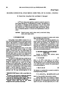
9) Crankshaft Inspection (1) To measure run-out of the crankshaft, support the crankshaft using a V block as shown in the right figure, apply a dial gauge to the crankshaft center journal, read the indication on the dial gauge rotating the shaft one turn gently. If the service limit is exceeded, correct or replace.
Crankshaft run-out (mm) Standard assembling value
Service limit
Less than 0.03
More than 0.06
(2) Check the crankshaft oil seal for damage or wear on the contact surface and oil hole clogging.
(3) Check the crankshaft journal and pin for damage, irregular wear (ellipticity, conicalness), and shaft diameter and grind the journal and pin if the service limit or repair value is exceeded and replace the bearing (bush) and connecting rod metal respectively with one of undersize. Measure the dimensions of the journal and pin in the AA and BB directions at the position 1 and 2 avoiding the oil holes.
T134
NOTE: Finishing accuracy when grinding the crankshaft to undersize shall be as follows. Ⓐ Ⓑ Ⓒ
R at pin and journal: Finishing accuracy: R around oil hole At max. part: At min. part:
T135
3R ± 0.2 1.6 Z(▽▽▼)
Irregular wear limit of crankshaft journal and pin (mm)
2R 0.5R
More than 0.05 Shaft dia. At Main crankshaft journal
Finish using #400 sand paper.
Outside dia. Finishing dimension STD. 47.964 – 47.965 U.S. 0.25 47.714 – 47.715 U.S. 0.50 47.464 – 45.465 Shaft dia. At crankshaft pin (∅)
T136
STD. U.S. 0.25 U.S. 0.50
Outside dia. Finishing dimension 40.964 – 40.975 40.714 – 40.725 40.464 – 40.475
Heavy Equipment Restoration Parts LLC Phone: 269 673 1638 email:
[email protected]
10) Flywheel and ring gear Inspection Check the ring gear and replace if damage or remarkable wear is noticed. When the wear is limited to a small area, remove the, ring gear, turn it about 90 degrees and shrinkage-fit to reuse it. To shrinkage-fit the ring gear, heat it to 120 – 150°C to allow it to expand.
T137
11) Cam shaft ass’y Inspection (1) Check the journal and cam for wear and damage and replace if the service limit is exceeded. (2) Correct insignificant uneven wear or scars on the cam surface using oil stone or the like. A. Height of intake/exhaust valve cams (mm) Standard assembling value
Service limit
26.56 – 26.63
Less than 26.1
B. Height of injection pump cams (mm) Standard assembling value
Service limit
33.94 – 34.06
Less than 33.8
T138
12) Timing gear Inspection (1) If pitting or remarkable wear is observed on the tooth face of gears, replace the gear. (2) Measure the backlash of gears and replace if the service limit is exceeded. Timing gear backlash (mm) Standard assembling value
Service limit
0.08
More than 0.25
T139
13) Oil flow
T140
14) Oil pump Disassembly Removal from engine (1) Remove the snap ring. (2) Take out the colar, spring and shim. (3) Take out the idle gear, vane, and oil pump cover together. (4) Extract the rotor and thrust washer. (5) Extract the oil pump cover from the idle gear. 1. 2. 3. 4.
Colar Shim Rotor Thrust washer
5. 6. 7. 8.
T141
Idle gear ass’y Oil pump cover Spring Snap ring
Inspection and reassembly (1) Check the oil pump cover, rotor and vane and replace if worn out or damaged remarkably. (2) Check the clearance between the rotor and vane and replace if the service limit (0.25 mm) is exceeded. (3) Reassemble in the order reverse to disassembly. ➀ Install the crankshaft gear and idle gear aligning the match mark. ➁ Adjust the side clearance of the rotor and vane to 0.1 – 0.15 mm. (See the assembling order 12, T162.)
T142
15) Oil filter Structure and Functions (1) The cartridge type oil filter is excellent in filtering performance. (2) Since it is of the full-flow type, when the filter is clogged, the safety valve is opened to allow the oil to flow, preventing seizure or other troubles. (3) The oil fed under pressure with the oil pump enters Ⓐ is filtered by the element, and supplied to each part from Ⓑ. When the element is clogged, the oil is supplied to each part without passing through the element. Replacement (1) Replace the oil filter every 200 hours of operation. (2) Coat the filter mounting surface with oil and tighten the filter by hand. (3) Do not reuse the filter if it is removed once.
T143
16) Water pump assembly and thermostat Disassembly (1) Remove the set plate gasket. (2) Remove the thermostat spring. 1. Water pump ass’y 2. Gasket 3. Set plate 4. Thermostat 5. Spring 6. Gasket NOTE: The pump main body is aluminum die cast and should be replaced as ass’y if subjected to water leakage or other troubles.
Specification and inspection
T144
Thermostat (1) Replace if the valve is opened even only slightly at normal temperature. (2) Immerse the thermostat in water, increase the water temperature gradually and check the valve opening temperature and valve lift. NOTE: 3 to 5 minutes are required until the valve is operated.
Model Type
C1.1 Wax pellet
Opening temperature
73° - 77°C
Full-opening temperature
87°C
Valve lift (at water temperature 82°C)
6.0 mm
T145
Reassembly Reassemble the components in the reverse order to disassembly.
17) Radiator Specifications and structure Structure Specifications (1) The radiator is provided with the plate fin having superior anti-vibration characteristics. (2) The radiator cap is of the pressure type (sealing type) for higher cooling efficiency. When the cooling water is heated to high temperature (high pressure), the pressure valve is pushed and opened to release excessive pressure from the overflow pipe (shown by white arrow mark). When the cooling water temperature reduces and the inside pressure becomes lower than the atmospheric pressure, the negative pressure valve is opened to protect the radiator from being crushed under the atmospheric pressure (shown by black arrow mark).
Fin type
Corrugated
Cooling water volume Pressure pressure
valve
starting
Negative pressure valve starting pressure Heat radiation volume
3.5 ℓ 68.6 – 88.2 kPa (0.7 – 0.9 kgf/cm2) – 4.9 kPa (0.04 – 0.05 kgf/cm2) 15,000 kcal/h
T146
Inspection (1) Check the radiator pipe for water leakage and repair or replace if unsatisfactory. (2) Check the radiator fin and remove dust, mud, or other foreign matter clogging in the air passage, if any. (3) Check the pressure valve and negative pressure valve of the radiator cap for valve opening pressure and sealing condition. Replace of defective. (4) Check the radiator hose and replace if damaged or aged. (5) If the net is clogged, remove and clean.
18) Fuel filter Fuel passage Fuel passage The fuel flows as shown in the figure from the tank, pressurized by the injection pump to high pressure, and fed to the nozzle and injected to the combustion chamber. The fuel after lubricating the nozzle needle is returned to the tank through the overflow pipe. 1. Tank 2. Fuel filter
3. Injection pump 4. Nozzle and holder
T147
Inspection If water, dust, or other foreign matter is observed in the transparent plastic case, clean and replace the filter if necessary.
Disassembly and reassembly (1) Remove the filter turning the filter ring nut counterclockwise. NOTE: Take care to the O-ring fitted between the ring nut and main body, coat with grease before tightening. (2) Coat the area of the element to be mounted to the main body with grease and install the element by hand.
19) Governor Structure and functions (1) Governor This governor is a mechanical all-speed governor. It is installed in the gear case. The fly weight ass’y is installed to the cam shaft and its movement is transmitted to the control rack of the injection pump through the slider control lever link. The spring which controls the movement of the fly weight is hitched to the arm COMPL and tension lever. The spring tension is changed by changing the governor lever so as to control the engine speed.
with torque control spring to realize bigger torque. A start spring is placed between the gear case and link. This spring automatically functions to increase injection amount of fuel at the time of engine start. The smoke set had been adjusted at the factory.
(2) Maximum speed set bolt A bolt is mounted on the cylinder block. This bolt limits the movement of the arm COMPL (unloaded maximum rpm). This bolt has been adjusted and sealed at the factory. (3) Smoke set, start spring These are built into the cylinder block, to regulate fuel injection amount at high speed range. Regulation of fuel injection amount at middle speed range is made
T148
20) Injection pump Specification
Disassembly, Inspection and Reassembly (1) Disassembly, inspection, and reassembly of injection pump. If the trouble has been verified to be in the injection pump, do not disassemble other than at shop specializing in this operation.
21) Nozzle and holder Specifications Part code
Ass’y No.
Nozzle type
Throttle type
Needle valve dia.
∅6
Pintle dia.
∅1
Valve opening pressure
11.27 – 12.25 MPa (115 – 125 kg/cm2)
Nozzle holder
Adjustment pressure
12.25 – 12.74 MPa (125 – 130 kg/cm2)
Nozzle
Injection angle
4°
Structure and functions The nozzle is finished super-precisely to inject the fuel which is fed from the injection pump under pressure to the combustion room in good condition. Components as shown in the right figure are incorporated. The fuel is fed under pressure from the oil hole of the nozzle holder main body to the nozzle body. When the pressure exceeds the specified value, it pushes the spring, injected from the nozzle, and at the same time lubricates and cools the nozzle and nozzle body. The oil leaking at this time is returned to the tank by the return pipe.
T149
Heavy Equipment Restoration Parts LLC email:
[email protected] Phone: 269 673 1638 T150
Disassembly and inspection (1) Place the nozzle holder (body) in a vice and disassemble turning the nozzle nut. NOTE: Take care not to allow the needle valve to drop when removing the nozzle. (2) Wash the nozzle and needle valve and check for seizure and sticking of the nozzle and fuel leakage on the seat surface. Correct fuel leakage of the seat by lapping. (3) Check the distance piece upper and lower contact areas and correct to be sticked closely. (4) Check the push rod for wear on the nozzle needle valve contact surface and check the spring seat for crack.
Reassembly and adjustment (1) When assembling a new nozzle ass’y, heat light oil to 50 - 60°C and remove the rust preventive oil in it. Slide the body and needle valve to ensure that they slide lightly. (2) Invert the body, place the shim, spring, rod, piece and nozzle on it in this order, cover the nozzle nut and tighten. (3) After assembly, check for the nozzle injection pressure. 1. Adjust by the adjusting washer (shim) so that the injection is started at 11.76 MPa (120 kgf/cm2) using a nozzle tester. 2. The pressure increases or decreases about 0.98 MPa (10 kgf/cm2) by a washer of 0.1 mm.
Heavy Equipment Restoration Parts LLC Phone: 269 673 1638 email:
[email protected]
T151 (4) Injection condition 1. Small drops should not be mixed in the spray. 2. The oil should be injected describing a cone by straight lines toward the center line of the nozzle. 3. Place white paper at about 30 cm from the nozzle and confirm that the spray is approximately circular when injected. 4. Keep the oil pressure lower by 1.96 MPa (20 kgf/cm2) than the specified value 11.76 MPa (120 kgf/cm2) and check that the test oil does not drop form the nozzle end.
22) Air Cleaner Structure and functions (1) The air cleaner is connected to the cylinder with the air cleaner hose. (2) The air cleaner is of the cyclone type incorporating filter element and removes dust from the intake air.
Inspection and replacement (1) Take out the element every 100 – 200 hours and blow compressed air (less than 0.686 MPa, 7 kg/cm2) from the inside and clean. (Clean the dust deposit on the dust pan also.) (2) If soot or oil has sticked to the element, immerse it in neutral detergent for about 15 minutes and then wash by shaking several times. Rinse in clean water sufficiently and dry naturally. (3) When the air cleaner is used in dusty place, clean it earlier. (4) After cleaning 6 times or once every year, replace the element with new one. (5) After completion of cleaning, apply light from the inside of the element and it should be replaced with new one if breakage, pin hole, and especially thinner part is observed or if the gasket is broken. (6) Do not use the element before drying completely.
T152
3. ★ 1. 2. 3. 4.
ENGINE REASSEMBLY Cautions before assembly Wash parts to be installed. (Especially wash oil passage bearing, piston and cylinder bore carefully.) Coat the sliding and rotating parts of the cylinder bore, piston, bearing and other parts with new oil before installing. Replace the gaskets with new ones. If necessary, use liquid packing to prevent oil leakage. Do not tighten bolts and nuts for aluminum alloy parts excessively. Tighten them with specified torque.
Reassembly 1. Relief valve assembly with O-ring. Relief valve tightening torque 59 – 69 N·m (6 – 7 kgf·m)
2. Crank shaft and bearing holder assembly. Cylinder block to bearing holder tightening torque 25 – 29 N·m (2.5 – 3.0 kgf·m)
NOTE: 1. Take care not to damage the bush in the cylinder block by the crank shaft gear when install the crank shaft and bearing holder assembly 2. Install the two hexagon socket head bolts for the fly wheel side bearing holder. 3. Measure the end play of crank shaft. Crankshaft end play Standard value
0.05 ~ 0.3 mm
Service limit
0.5 mm
T153
T154
Heavy Equipment Restoration Parts LLC Phone: 269 673 1638 email:
[email protected]
3. Oil seal 4. Rear plate NOTE: Apply the liquid gasket to around the M 10 screw holes for rear plate. Rear plate tightening torque: 46 ~ 54 N·m (4.7 ~ 55 kgf·m)
5. Fly wheel Align the hole to the roll pin on the crankshaft. Fly wheel tightening torque 69 – 78 N·m (7.0 ~ 8.0 kgf·m) T155 6. Piston and connecting rod assembly ➀ Coat the metal surface, piston and piston ring with engine oil. ➁ Turn the ring to allow the oil to ensure the ring groove sufficiently, and set the ring end gaps at 120° respectively avoiding piston pin direction and the direction at a right angle to the piston pin. ➂ Insert the ring facing the connecting rod figure match mark toward the injection pump side, using ring pliers. NOTE: Place the smallest connecting rod figure match mark to the front side so that the figures increase gradually. ➃ Tighten the connecting rod cap with the specified torque and check for the axial play. Connecting rod tightening torque T156
29 ~ 34 N·m (3.0 ~ 3.5 kgf·m) NOTE: 1. After tightening, confirm that the crankshaft moves lightly. 2. The connecting rod should move 0.1 – 0.3 mm in the axial direction. 7. Suction pipe and Suction filter ➀ Fit an O-ring to the suction pipe and insert the suction pipe to the cylinder block. ➁ Place the suction pipe end into the suction filter and fix the suction filter. Suction filter tightening torque 9 ~3 N·m (0.9 ~ 1.3 kgf·m)
T157
8 Oil pan Start tightening the bolts of the oil pan from the center, then tighten the opposing bolt on opposite side on the diagonal and specified torque. Oil pan tightening torque 10 – 12.7 N·m (1.0 – 1.3 kgf·m)
9 Oil level gauge and Gauge guide
T158
Install the oil level gauge and gauge guide using 2 O-rings. 10 Front plate Install the front plate together with the gasket. 11 Cam shaft ass’y · Tachometer shaft · Plate ➀ Install the tachometer shaft. ➁ Install the cam shaft ass’y (taking care to the bearing). ➂ Fix the tachometer shaft and cam shaft ass’y with the plate. Plate tightening torque 9 ~ 13 N·m (0.9 ~ 1.3 kgf·m) T159 NOTE: Install the timing gear case taking care so that the slider is not dislocated from the guide pin. 12 Idle gear · Oil pump ass’y ➀ Install a thrust washer to the idle gear shaft. ➁ Install the idle gear ass’y. ➂ Align the match marks of the idle gear, crankshaft gear and cam shaft gear and install idle gear ass’y to the idle gear shaft. ➃ Install the rotor. ➄ Install the oil pump cover, shim, spring and collar and fix with a E shape clip.
Heavy Equipment Restoration Parts LLC Phone: 269 673 1638 email:
[email protected] T160
NOTE: 1. Coat the rotor and vane both sides with grease before installing them. 2. Never turn the crankshaft until the timing gear case is installed. 3. Turn the oil pump cover clockwise and counterclockwise, fix the hole at the center of the spring pin inserting hole moving distance, and then install the gear case.
➅ Adjust the shims so that the oil pump, rotor and vane side clearance is 0.1 – 0.15 mm.
13 Timing gear case
T161
T162
➀ Untighten the lock nut and remove the low idle set bolt. ➁ Install the start spring between the timing gear case and governor link. ➂ Inserting the link into the cylinder block hole while turn the governor lever to clockwise and hold it, and then install the timing gear case. ➃ Reinstall the low idle set bolt and secure the lock nut.
T163
14 Crankshaft pulley Install the key and assemble the crankshaft pulley and crankshaft. Crankshaft pulley tightening torque 118 ~ 127 N·m (12 ~ 13 kgf·m)
T164
15 Injection pump assembly ➀ Fit the shim which has been removed at the time of disassembly, connect the control rack of the injection pump and link, and fix with the snap pin. ➁ Tighten the injection pump with bolts and nut. Injection pump tightening torque 5 ~ 7 N·m (0.5 ~ 0.7 kgf·m)
T165 16 Injection timing adjustment Usually the injection timing is adjusted properly by the step of the order 15. When the injection pump, cam shaft assembly or cylinder block is replaced, adjust the injection timing in the following procedure. ➀ Install the injection pump inserting a shim of 0.5 mm in thickness according to the procedure of order 15. ➁ Remove the delivery valve holder on the injection pump front side (radiator side). ➂ Extract the delivery valve and spring and reinstall the delivery valve holder. ➃ Move the governor lever in the fuel increasing direction and flow the fuel near 25° before compression TDC of the No. 1 piston (front side) and then the fuel flows out of the delivery valve holder. ➄ Turn the crankshaft gently clockwise from the condition of above (4), and then the fuel flowing out of the delivery holder stops. Read the piston position before TDC at this time. If it is late more than 23° decrease the shim thickness and if earlier more than 25° increase the shim thickness.
Heavy Equipment Restoration Parts LLC Phone: 269 673 1638 email:
[email protected]
T166
Engine Model Injection timing (before TDC) Piston displacement (before TDC)
C1.1 23 ~ 25° 4.217 ~ 4.96 mm
Cat C1.1 Diesel Engine Service and Workshop Manual Engine Model C1.1 Piston displacement to crankshaft angle (before TDC)
NOTE: 1. When shim is not required, coat required packing before installing. 2. The injection timing varies about 2° with 0.3 mm of shims. 3. Mix assemble a shim (0.5 mm) without beading when you need adjusting shims more than 1.0 mm. 4. Thickness is stamped on the shims.
(°)
Displacement
(°)
Displacement
20
3.206
25
4.963
21
3.529
26
5.356
22
3.866
27
5.763
23
4.217
28
6.184
24
4.583
Injection timing adjusting shim
➅ Install the delivery valve and spring in the injection pump.
Thickness (mm)
Part code
0.2
131437310
0.3
131437320
0.4
131437330
0.5
131437340
*0.5
*131437630 (* without beading)
Delivery holder tightening torque 39 ~ 44 N·m (4.0 ~ 4.5 kgf·m)
T167
17 Oil filter Coat the mounting surface with a small quantity of oil and tighten by hand. 18 Engine stop solenoid Tighten the engine stop solenoid lightly by pliers.
Heavy Equipment Restoration Parts LLC Phone: 269 673 1638 email:
[email protected]
19 Tappet Coat the oil to tappets and install.
60
20 Cylinder head ➀ Position each of the pistons at top dead center and, using a dial indicator, determine the distance each piston projection above the face of the block. NOTE: Measure each of the pistons while holding a slight down pressure on the piston. Use the dimension taken from the cylinder which has the greatest projection and select a head gasket as indicated in the following chart. T168 NOTE: The variation in the amount of protrusion among all pistons must be within 0.1 mm. Measured value (mm)
C1.1
Tightened Thickness
More than 0.55 – under 0.65
t = 1.2
More than 0.65 – less than 0.75
t = 1.3
NOTE: Lowest for digits of code numbers are stamped on the head gasket. Install head gasket with code numbers at top.
➁ Tighten the cylinder head in several steps in the order as shown in the right figure and tighten with the specified torque finally. Cylinder head tightening torque 49 ~ 52 N·m (5.0 ~ 5.3 kgf·m) NOTE: 1. Take care to the spring pin which positions the cylinder head ass’y. 2. Coat the thread with grease containing disulfide molybdenum.
T170
Heavy Equipment Restoration Parts LLC email:
[email protected] Phone: 269 673 1638
21 Oil pipe Eye bolt tightening torque 10 ~ 13 N·m (1.0 ~ 1.3 kgf·m)
T171
22 Push rod Rocker arm ass’y Install the push rod and rocker arm ass’y Rocker arm ass’y tightening torque 20 ~ 25 N·m (2.0 ~ 2.5 kgf·m)
23 Valve clearance adjustment
T172
Untighten the nut of the intake and exhaust valves and adjust to 0.2 mm with adjust screw. NOTE: 1. Adjust the valve clearance while cold. 2. Set the No. 1 cylinder at the compression TDC, adjust the valve clearance of the No. 1 intake and exhaust valves, and No. 2 exhaust valve, turn the crankshaft 240° counterclockwise when viewed from the front side, and adjust the No. 2 intake, and No. 3 intake and exhaust valves. 24 Head cover Evenly tighten the cylinder head cover, taking care on the packing.
T173
Head cover tightening torque 10 ~ 12 N·m (1.0 ~ 1.2 kgf·m)
Heavy Equipment Restoration Parts LLC email:
[email protected] Phone: 269 673 1638
25 Water pump ass’y · Radiator hose 1. 2. 3.
Water pump ass’y Radiator hose (upper) Radiator hose (lower)
26 Glow plug · Connector T174
Glow plug tightening torque
8 – 15 N·m (0.8 – 1.5 kgf·m)
27 Oil pressure switch Oil pressure switch tightening torque 15 ~ 20 N·m (1.5 ~ 2.0 kgf·m)
28 Nozzle and holder ass’y Tighten the cap and gasket positively, tighten with specified torque using a nozzle holder socket, and install the return pipe. Nozzle and holder tightening torque
59 – 68.6 N·m (6.0 – 7.0 kgf·m)
29 Return pipe COMPL · Injection pipe Injection pipe After installing the return pipe, install the injection pipe. Injection pipe tightening torque
1. Nozzle and holder 2. Return pipe 3. Injection pipe T176
19.6 ~ 24.5 N·m (2.0 ~ 2.5 kgf·m) 30 Alternator ass’y Install the alternator ass’y taking care to the direction of the adjusting plate.
Heavy Equipment Restoration Parts LLC email:
[email protected] Phone: 269 673 1638
31 Drive gear assembly, Hydraulic oil pump and power steering oil pump ➀ Install the drive gear assembly to the hydraulic pump and then install them to the gear case. ➁ Install the power steering oil pump to front of the gear case.
T177
32 V belt · Fan pulley · Cooling fan ➀ Install the fan pulley and cooling fan and then V belt. ➁ Adjust the belt tension with the alternator so that it is deflected 5~10 mm at the middle point between the crankshaft pulley and alternator pulley when depressed by a finger (about 5 kgf) and tighten. Cooling fan tightening torque 8.8 ~ 12.7 N·m (0.9 ~ 1.3 kgf·m)
33 Exhaust manifold (Muffler assembly) 34 Pressure plate · Clutch disk Install the pressure plate and clutch disk referring to paragraph 3-2, Clutch. T178
64
2-5
Trouble Shooting
Trouble
Engine does not start.
Cause
Defective key switch Connect or correct contact points propely. Insufficient charging or completely discharged Charge. battery. No fuel. Replenish the fuel. Air mixed in the fuel system. Correct points allowing the air to enter the fuel. Clogged fuel filter. Replace the fuel filter. Irregular of improper fuel supply. Trouble of injection pump. Have corrected in work specified by Nippon Denso. Defective glow plug. Replace to disconnected wire of glow plug. Improper viscosity of lubricating oil. Check and change. Clogged air cleaner. Clean the air cleaner. Not compression. Check an correct each part. Defective engine stop solenoid. Check or replace wiring. Trouble of IOS system. Refer to 3-8 Electric Units and Accessories. Air mixed in the fuel system. Uneven fuel injection.
Irregular engine speed Clogged fuel filter. Trouble of speed governor. Improper function of engine main body. Engine stops during operation
No fuel in fuel tank. Clogged fuel filter. Air mixed in the fuel system. Improper functions of engine main body. Insufficient cooling water.
Engine overheat
Remedy
Discharge air from the fuel. Trouble of injection pump. Have corrected or replaced in a work specified by Nippon Denso. Replace the fuel filter. Check and adjust. Overhaul, check and correct each part. Replenish fuel. Replace the filter. Correct points to allow the air to enter the fuel system. Check and correct each part.
Replenish the cooling water, and check and repair water leaking points. Loosened or slipping fan belt. Clean oil dust, etc. and retighten. Failure of fan belt. Replace. Clogged radiator. Clean the radiator. Clogged radiator fin. Clean. Cooling water passage clogged with dust, fur, etc. Wash. Improper function of thermostat. Check and replace Insufficient lubricating oil. Replenish. Overload. Decrease the load.
Trouble
Cause
Remedy
Improper color of engine exhaust (white or blue)
Too much engine oil. Too low viscosity of engine oil. Improper injection timing.
Check and adjust the quantity. Check and change. Too late. Correct.
Improper engine exhaust (black or dark gray)
Improper fuel. Excessive fuel injection. Damaged engine block. Overload. Clogged air cleaner.
Check and change. Check and adjust. Check an correct each part. Reduce the load. Clean the elemente.
Improper charging.
Loosened fan belt. Trouble in wiring of each part. Defective battery. Defective alternator.
Correct belt tension. Check and repair. Replace. Replace.
Loosened or disconnected wiring of each part. Dropped battery voltage. Starter does not operate. Defective safety switch. Trouble in starter.
Oil pressure lamp does not go out.
Oil pressure lamp does not light up with the key switch turned ON. (While engine stops.)
Insufficient engine oil. Trouble in pressure switch. Oil leakage from lubricating system. Clogged oil filter. Short circuit between oil pressure lamp and oil pressure switch.
Check and install or tighten. Charge the battery. Replace. Check and correct the starter. Replenish to specified gauge level. Replace the switch. Check and retighten. Replace with new one. Repair.
Burnt out lamp. Replace the lamp. Disconnected wire between battery and oil Repair. pressure lamp.
2-1 Engine Sectional View
T100
T101
Heavy Equipment Restoration Parts LLC email:
[email protected] Phone: 269 673 1638