Principle and Application of Vibrating Suction Method* Tao Zhu
Rong Liu, Xu D. Wang, Kun Wang
School of Aeronautical Science and Engineering BeiHang University Beijing, People’s Republic of China
[email protected]
Robotics Institute BeiHang University Beijing, People’s Republic of China
[email protected]
Abstract – In this paper a new suction-to-wall method is presented, which is called vibrating suction method(VSM). With this method, the vacuum in the suction cup is established through high-frequency vibration of the cup with respect to the wall surface. First, the principle of the VSM is studied. Based on some assumptions, the mathematic model of a vibrating suction cup is built. Then numerical simulation of the model shows the relationship between the pressure in the cup and vibration frequency and amplitude. In the end, a prototype of suction module is designed based on the principles of the VSM, and wall suction experiments prove the effectiveness of this module. This new-style suction module is supposed to be used in miniature wall climbing robot.
method(VSM). This paper will mainly study the principle of the VSM and give an example of how it can be applied practically. The following sections will be arranged as this: the vibrating processes and corresponding airflow in a suction cup are analyzed in section 2. Then mathematic model of the vibrating suction cup is built in section 3, and experiments on one size of vibrating cup are carried out to testify the model. In section 4 a suction module based on the VSM is designed and made, adsorptive tests on different wall-surfaces prove the effectiveness of the module. Section 5 gives some future jobs and conclusions are made in Section 6. II. THE VIBRATION OF SUCTION CUP
Index Terms – Vibrating Suction Method; Suction Module; Wall Climbing Robot.
I. INTRODUCTION For a wall-climbing-robot, the most important issue is obviously how to stay on the wall safely and reliably. Generally, the methods adopted by the wall-climbing robot to adsorb itself to the wall can be classified into four: electromagnetic force, adhesive material, molecular force and negative pressure. While electromagnetic adsorption has the advantages of great adsorption edge and easy control, it can only be applied on the ironic surface [1] [2]. Adsorption through adhesive material not only demands higher surface quality of the wall, but also is less reliable [3]. Molecular force is a new adsorption method inspired by the gecko bristle, and appears feasible in recent years with the development of the MEMS technology, but this technology is not grown-up enough to be applied practically[4]. Right now, the most widely used means in wall climbing robot is still the suction cup, in which negative pressure or vacuum is established by using vacuum ejector or vacuum pump. This adsorption method has the advantages of higher reliability and easier application compared with other ways [5]. However, the vacuum ejector always needs high-powered air compressor and long air tube, and the vacuum pump is usually heavy and complicated to control, these demerits limit the application of this adsorption method on wall-climbing robot, especially for small or micro ones. In this paper, a new suction-to-wall method is presented, with which the vacuum in the suction cup is established by high frequency vibration of the cup with respect to the wall surface. So this method is referred to as vibrating suction *
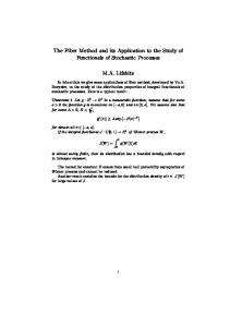
When an ordinary suction cup is pushed down against a wall, usually it will not drop soon because the air in it is squeezed out and the internal pressure is less than the atmospheric pressure. With the time going, the air outside will
Fig. 1. A vibration cycle of the suction infiltrate through, and the internal pressure will increase until the cup drops. The time that the cup can adsorb on the wall depends on many factors, in which the brightness and cleanness of the wall surface are the main ones. Anyway, it is easy to find out from above phenomenon that if we could push down the suction cup repeatedly each time before it drops the cup would stay on the wall forever. It is based on this idea that the VSM is conceived. When a suction cup is vibrating with respect to wall, the airflow in it is illustrated with the Figure 1. In Fig.1(a), the cup is in initial position, in which the pressure inside the cup Pi is equal to the one outside Po, namely Pi=Po, and the air flows neither in nor out of the cup; In Fig.1(b), the cup is in
This work is partially supported by the “211project” of the Ministry of Education of P.R.China
the process of pulling up, the enlargement of interspace in the cup makes Pi
Po, the air inside the cup will be squeezed out of the cup, which results in the slowing down of the speed of the increase of Pi and limits the positive level of Pi. Therefore the overall average pressure in the cup during a whole vibration cycle is negative. Form above analysis, the vibration processes between the suction cup and the wall surface can be approximately regarded as the action of a vacuum pump, which allows the inside air easy to go out and outside air difficult to come in, so the negative pressure is generated. However, the generation of negative pressure by the VSM is more efficient than that by the vacuum pump, because the VSM directly convert the mechanical energy into the potential energy of air pressure, without any intermediate energy consumption processes. Although there exit periods of positive pressure in the VSM cup, this problem could be solved by utilizing several cups which vibrate alternately. The detailed design will be discussed in Section 4. III. MODEL OF THE VIBRATING CUP A. Mathematic Model The building of the mathematic model of the vibrating cup is based on the following assumptions:
uo2 Po = + + h fo ρ 2 ρ
(4)
dm = − L1 ⋅ uo dt
(5)
Pi and
when Pi
Po
ρ
=
ui2 Pi + + h fi 2 ρ
(6)
and
dm = L2 ⋅ ui dt
(7).
4) When Pi>Po, as the Pi increases, the air becomes more and more easy to go out, then it is assumed that (8) h fo = h fo 0 − k1 ( Pi − Po ) When Pi
m -the numbers of MOL inside the cup; R -universal gas constant; T -the environment temperature; ρ -the density of the air; u -the velocity of the air flow, ui is the velocity of the air flows in, uo is the velocity of the air flows out; energy dissipated by friction,
h fi is the energy dissipated by
the friction when the air flows into the cup, Fig. 2. The conical figure of the cup 1) In order to simplify the calculation, the interspace between the cup and the surface is assumed to be conical during vibrating(see Fig.2). If the basic actuation function is (1) x = h sin( wt ) then the volume of the interspace is
1 V = π r 2 ( H + x) 3
(2)
h fo is the energy
dissipated by the friction when the air flows out of the cup; L -the leakage coefficient, it is related to the radius of the cup, the quality of the wall surface, etc., L1 is the leakage coefficient when the air flows out, L2 is the leakage coefficient when the air flows into the cup; k -the coefficient of the energy consumed by friction, it is related to the coarseness of the wall surface and the size of the cup, k1 is the coefficient when the air is squeezed out, k2 is the coefficient
2) The air inside is assumed to be the ideal gas, then
PV = mRT i
h f -the
(3)
3) As the air pass through the narrow gap between the cup rim and the wall surface, the potential energy of air pressure is converted into kinemic energy, and it is assumed that part of the energy is dissipated because of the friction. When Pi>Po, then
when the air is sucked into the cup. It can be seen from above equations that the key to build the mathematic model which matches the real response is to determine the value of the following coefficients: h fi , h fo , L1 , L2 , k1 , k2 . At first, we estimate a set of initial values of these coefficients by experience. Then we modify
them repeatedly until the response of the model matches the experimental results. The numerical simulation of the mathematic model is carried out in the MATLAB program environment. Fig.4(a)and(c) are the time-responding curves of the pressure in the cup at different angular frequencies. It can be concluded from these curves that the air pressure transformation in a vibration cycle accords with the one predicted qualitatively in Section 2. The overall average pressure in Fig.4(a) can be calculated as P = 9.12 × 10 pa < Po , which is less than 4
atmospheric pressure, indicating that the suction force can be generated from the vibration of the cup. B. Experimental Test In order to know the changes of the pressure Pi in practice and to compare them with the simulation results, an experimental apparatus is designed(Fig.3). With this apparatus, the vibration frequency can be modified by changing the rotate speed of the actuating motor and the vibration amplitude can be adjusted by changing the length of D(h).
proves the correctness of the mathematic model to some degree. Much more experiments with different amplitudes and frequencies of actuation have been done. The average pressure
P of each experiment is calculated and compared with corresponding simulation result. As shown in Fig.4(e) or (f), a 3-dimention coordinate system is utilized to illustrate the change of average pressure P with respect to the frequency and the amplitude of actuation. The colorized rectangles on the P surface represent different values of P at different frequencies and amplitudes of the actuation. It can be seen that the overall shapes of the P surface for simulation and experiment are very similar, also the position, width and direction of those corresponding colorized rectangles on two surfaces resemble well. These similarities further prove the correctness of the model. In addition, it can be seen from the P surfaces that all average pressures are less than atmospheric pressure, which means the average pressure in the suction cup is negative and the cup will be adsorbed to the wall. Furthermore, the
P surface declines when the frequency or the amplitude increases, which indicates that the negative pressure or suction force in the cup can be enhanced by the means of increasing the frequency or the amplitude of the actuation. IV. DESIGN OF PROTOTYPE SUCTION MODULE
In above Sections, all analyses and experiments are done to only one suction cup. As the real pressure in one vibrating cup could be positive in some time, only one vibrating cup can not be used as a foot of wall climbing robot. However, if we integrate several vibrating cups in one suction module, and make sure that at any time there are cups in negative pressure state, then the suction module can adsorb on the wall and can be used as a single robot foot. There are many mechanism designs of suction module which can achieve the performance described above. In this section, an example of suction module design is presented, and a prototype is fabricated and tested on walls.
Fig. 3. The mechanism of the experimental apparatus The signal from the pressure sensor, which is fixed on the wall surface under the cup, is collected, stored and analysed in the Labview environment. The experimental pressure curves at two different vibration frequencies are shown in Fig.4(b) and (d), respectively. By comparing the simulation curves(Fig.4(a) and (c)) with the experimental ones, we can see that the corresponding curves are very similar in profile, especially the ranges of pressure fluctuation match well. This similarity
A. Module Design As shown in the explosive view of Fig.5 (a), there are two circular plates in the suction module, which could be referred to as upper plate(No.4) and lower plate(No.5) respectively. These two plates are connected together by three prismatic joints, which are distributed equably on the rims of the plates. On the upper plate, an electric motor is mounted on its top side, and the motor drives an eccentric wheel(No.1) to rotate. On the lower plate, a T-shape part with a rectangular orifice(No.2) is fixed on its top side. After two plates are assembled together, the eccentric wheel will be in the rectangular orifice, and they work as a cam to cause the relative vibration between two plates. On the bottom side of each plate, three rubber cups are mounted with equal angular space of 120°. After two plates are assembled, there are
altogether six cups, which are distributed alternately with a cup of one plate between two cups of another plate. When two plates on the suction module begin vibrating, the cups on them will also vibrate relatively with the phasic difference of 180°. Therefore, if we put the vibrating suction module on the wall, it can be assured that at anytime there are three cups on one plate which are in the process of being pulled out of the wall, and the pressure in them is negative. B. Testing Based on above design, a prototype of suction module is fabricated, which is shown in Fig.5 (b) and (c). The diameter of the plates is 75mm, and the diameter of the rubber cups is 25mm. The maximum vibrating frequency of this module is about 8Hz when the motor is at rated rotate speed. The vibrating amplitude, which is determined by the eccentric cam, is 1mm. Some experiments have been done with this suction module on different kinds of wall. On the glass wall surface the module can adsorb at very low vibrating frequency, or even without vibration. On the coarse surface, such as painted wood-board or washed wall, the module can not adsorb by itself without vibration. While at higher frequency, the module can stay on these coarse surfaces as long as it keeps vibrating.
Fig. 4. Time-responding curves of Pi
V. FUTURE WORK
1) To prove that the VSM is more efficient than regular vacuum ejector or pump;
(a)
(b) Fig. 5. The prototype of the suction module
(c)
2) To optimize the vibrating module to achieve lighter weight, lower power consumption, smaller size, etc.; 3) To develop a wall climbing robot using the suction module presented; VI. CONCLUSIONS
This paper presents a new-suction-to-wall method called Vibrating Suction Method(VSM), which utilizing vibration to generate negative pressure in a suction cup. Mathematic model of the VSM is built based on some reasonable assumptions. Numerical simulation of the model is performed, which demonstrates that the average pressure in a suction cup is negative although the pressure may goes above the atmospheric pressure in some time. An experimental apparatus is designed to test the characteristics of the vibrating cup. The experimental results prove the correctness of the mathematic model. And the average pressure in the cup will decreases as the frequency and/or the amplitude of vibration increases. A prototype suction module based on VSM is fabricated and tested on the wall. Although it is only a simple experimental module, it proves the feasibility of the VSM. REFERENCES [1] W. Shen, J. Gu, and Y. Shen, “Permanent Magnetic System Design for the Wall-climbing Robot,” Proceedings of the IEEE International Conference on Mechatronics & Automation, vol. 4, pp. 2078 - 2083, July 29-Aug. 1, 2005. [2] W. Shen, J. Gu, and Y. Shen, “Proposed Wall Climbing Robot with Permanent Magnetic Tracks for Inspecting Oil Tanks,” Proceedings of the IEEE International Conference on Mechatronics & Automation, vol. 4, pp. 2072 - 2077, July 29-Aug. 1, 2005. [3] Kathryn A. D., Andrew D. H., Stanislav G., “A small wall-walking robot with compliant, adhesive feet,” Proceedings of IEEE/RSJ International Conference on Intelligent Robots and Systems, 2005, pp. 3648 – 3653, Aug. 2005. [4] Sitti M., Fearing R.S., “Synthetic gecko foot-hair micro/nano-structures for future wall-climbing robots,” Proceedings of IEEE International Conference on Robotics and Automation, 2003, vol. 1, pp. 1164 - 1170, Sept. 2003. [5] Y. Wang, S. Liu, D. Xu, “Development & Application of Wall-Climbing Robots,” Proceedings of the 1999 IEEE International Conference on Robotics & Automation, vol. 2, pp. 1207 - 1212, May 1999.