Encapsulation and Reliability of Flexible Organic Photovoltaic Cells Claire Arneson 1
Introduction
As energy usage around the globe continues to rise, the time dedicated to searching for costeffective renewable energy schemes rises as well. Photovoltaic cells, which are already on the market, have significant drawbacks, including their heavy weight and slow and expensive manufacturing process. Organic photovoltaic cells (OPVs) are uniquely qualified for highspeed and cost effective manufacturing processes, such as roll-to-roll manufacturing. In order for the roll-to-roll manufacturing of OPVs to realized in a commercial market, a suitable encapsulation scheme must be researched and tested. This will provide a solid framework for integrating solar energy as a major renewable energy source.
1.1
Encapsulant Requirements
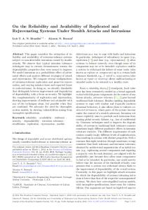
In an OPV, current is generated from a charge separation occurring at the interface of the photoactive organic donor and acceptor materials. The organics found in the donor and acceptor layers are both necessary and fragile components of OPVs. Any defect or degradation of these layers will decrease the efficiency of the device. A device with low efficiency is undesirable as it increases the cost per kilowatt hour. There are two main sources of degradation: defects occurring during deposition and degradation caused by exposure to water vapor and oxygen. Currently, inflexible OPVs are fabricated on glass substrates using vacuum thermal evaporation (VTE). Prior to deposition, the substrate undergoes a rigorous cleaning process, including a 4-step sonication process [1]. Care taken during cleaning and the use of VTE helps to ensure even deposition of organics and metals and decreases degradation caused by defects. In rigid encapsulation schemes, a glass or quartz encapsulation layer is sealed to the substrate using UV-curing epoxy. This creates a capsule that is impermeable to oxygen and water vapor, see Figure 1. In a flexible device, a similar capsule must be constructed out of flexible materials. The water vapor transmission rate (WVTR) must be less than 10-6 m2 /g/day [2]. Additionally, barrier layers must be mechanically robust and have good transmittance properties. These layers must be resistant to UV-degradation as well. Edge sealing techniques that work effectively with flexible barrier layers must also be researched.
1
2 Potential Barriers and Edge Seals
2
Fig. 1: Capsule Structure
2
Potential Barriers and Edge Seals
Following the popularity of OPVs, a market for flexible films that are durable in high UVexposure and good at stopping water vapor transmission has grown. Samples of four films were obtained for optical and mechanical testing: DuPont Kapton, Nexolve Optinox, 3M Ultra Barrier Film (UBF), and Covestro Dureflex. Edge sealing techniques in addtion UVcuring epoxy were researched and a sample of ADCO HelioSeal tape was obtained for use in testing. Additional studies on using UBF and HelioSeal tape suggest successful application in OPV encapsulation [3].
3 3.1
Capsule Testing Optical
Transmittance of light within the range of about 400-1100 nm is vitally important for the function of an OPV. Using a UV-vis spectroscopy instrument, the transmittance of the four films was tested. The UV-vis uses a beam splitter to send two monochromatic light sources to a photodetector. One beam passes through unobstructed air while the second passes through the film of interest. The photodetector measures the intensity of the beams and uses this information to calculate transmittance. These measurements were taken for the four barrier films and one polyimide, Nexolve CP1, a potential interlayer. Kapton was available in three varieties: PV101, PV102, and PV103. The transmission spectrum was compared to that of quartz, a common inflexible substrate material, see Figure 2. The Kapton and Dureflex films do not have suitable transmittance for OPV top layer encapsulation. The mechanical properties of Kapton make it suitable as a potential back barrier layer. Optinox and UBF had the most promising transmittance properties, so these two films were examined more closely. See Figure 3. While both films have optical properties comparable to those of quartz, UBF had much more robust mechanical properties, being somewhat rigid while remaining flexible. UBF does show poor transmittance in the ultraviolet and infrared range, however between these extremes the transmittance is excellent and this range is sufficient for the needs of solar cells. It should be noted that oscillations occurring in Figure 2 and 3 result from Fabry-Perot optical interference. In conclusion, UBF was chosen for further mechanical testing and compatibility testing with edge sealing techniques.
3 Capsule Testing
3
Fig. 2: Transmission data for various barrier layer materials
3.2
Mechanical
Mechanical testing was done on square capsules measuing 1.25” by 1.25”, approximately the size that would need to be constructed for small area devices. The purpose of this testing was to analyze mechanical properties of the barrier layers and edge seal so devices were not grown in the capsules. The first capsules constructed used UV-curing epoxy as an edge seal; however, the absorptive properties of UBF in the UV wavelengths prevented the epoxy from curing. The next capsules were constructed using HelioSeal tape. Pieces of tape were cut in to frames with widths of 0.25” and 0.125”, see Figure 4. Capsules were constructed as 3-layer packages: UBF-HelioSeal-UBF. These packages were heated to 130◦ C in between two metal plates on a hotplate for even heating as well as even pressure across all sides of the device. Significant pressure was applied to ensure a good seal between the two layers of UBF. After allowing the capsule to cool, mechanical testing was done. The first preliminary testing was simply to test the adhesion of HelioSeal tape to UBF. This was tested by tearing apart the two UBF layers. They could not be torn apart cleanly, which showed good adhesion to both layers. Next, the flexibility of capsules was tested by considering the bending radius. The capsules could be bent around a 0.75” diameter cylinder without showing damage. The HelioSeal tape does not cure to a rigid form, which allows the two layers of UBF to shear over one another without breaking the seal. This bending radius is smaller than the necessary requirement for roll-to-roll processing.
3 Capsule Testing
4
Fig. 3: Transmission data for Optinox and Ultra Barrier Film.
Fig. 4: Top-view diagram of a UBF-HelioSeal-UBF capsule.
4 Conclusions
3.3
5
Water Vapor Transmission
The organic photoactive materials used in OPVs require a WVTR less than 10-6 m2 /g/day. Before fabricating devices using the UBF-HelioSeal-UBF encapsulation scheme, WVTR must be measured. This can be done using the electrical calcium test. The electrical calcium test uses the change in resistance of calcium over time to determine WVTR, as seen in equation 1 [4]. In order to do this, a layer of calcium 250 nm thick will be deposited on the backside encapsulant layer of UBF. A top encapsulant will be sealed over the calcium using HelioSeal tape. This capsule will then be placed in a humidity-controlled environment. The humidity controller has four spaces that can be set to four different relative humidity levels. The level of humidity in each space is controlled by three input valves connected to a humidifier, a dry air source, and a pump. Humidity in each space is measured using a DHT-22 sensor connected to an Arduino. Depending on the humidity of each environment, a 0 or 1 is sent to each valve instructing it to open or close. Humidity can be specified within 1% of the specified value. Additionally, a voltage divider is attached to the Arduino controller and will be used to calculate the resistance of the calcium, as seen in equation 2. This portion of testing has not yet been completed, as the calcium needed for deposition was not available at the time of writing. MH2 O l d R1 δρ (1) W V T R = −n MC a b dt 5 − V0 RCa = ( )R2 (2) V0
4
Conclusions
In conclusion, the UBF-HelioSeal-UBF capsule satisfied both mechanical and optical requirements necessary for encapsulating OPVs. Further testing must be done to study the WVTR properties of the UBF-HelioSeal-UBF capsule. Additionally, new methods for applying HelioSeal tape must be explored so that devices deposited in the capsules are not damaged during construction. When a successful flexible encapsulation scheme is found, lifetime testing and experimental roll-to-roll processing should be explored.
5
Acknowledgements
First, I would like to acknowledge the NSF for funding this REU program, and the University of Michigan for hosting this specific program. Second, I would like to thank Professor Stephen Forrest and his graduate student, Quinn Burlingame, for their mentorship, assistance, and advice throughout the entire program. In addition, I would like to thank all the post-doctoral fellows, graduate students, and undergraduate students in the Optoelectronic Components and Materials group. I would also like to acknowledge Shahar Dror, a former undergarduate researcher in the OCM group, who designed the humidity controller. Finally, I would like to acknowledge the Lurie Nanofabrication Facility on the University of Michigan campus for housing the device fabrication facilities.
5 Acknowledgements
6
References [1] Burlingame Q, Song B, Ciammaruchi L, Aanotti G, Hankett J, Chen Z, Katz EA, Forrest SR. Reliability of Small Molecule Organic Photovoltaics with Electron-Filtering Compound Buffer Layers. Advance Energy Materials 6, 2016. [2] Lewis J. Material Challenge for flexible organic devices. Materials Today 9: 38-45, 2006. [3] Weerasinghe HC, Vak D, Robotham B, Fell CJ, Jones D, Scully AD. New barrier encapsulation and lifetime assessment of printed organic photovoltaic modules. Solar Energy Materials and Solar Cells 155:108-116, 2016. [4] Paetzold R, Winnacker A, Henseler D, Cesari V, Heuser K. Permeation rate of measurements by electrical analysis of calcium corrosion. Review of Scientific Instruments 74:5147-5150, 2003.