Module 3 DC to DC Converters Version 2 EE IIT, Kharagpur 1
Lesson 18 Analysis of Buck Converter (DC-DC) Circuit Version 2 EE IIT, Kharagpur 2
Instructional Objectives Study of the following in respect of the buck converter (dc-dc) circuit, with inductive (R-L) and battery (or back emf = E) load, assuming continuous conduction •
Derivation of the expressions for the maximum and minimum load currents
•
Calculation of the following:
(a) the duty ratio for the limit for continuous conduction (b) the average value and the ripple factor of the load current (c) the harmonic components of the output voltage waveform
Introduction In the last lesson − first one in the module (#3), firstly the circuits of the various types of dcdc converters (choppers), such as buck, boost and buck-boost, were presented. Then, the operation and the derivation of the expressions for the output voltage for the above dc-dc converters, including current waveforms, were described in detail. Lastly, the different control strategies used were briefly discussed. In this lesson − the second one in this module, the analysis of the buck converter (dc-dc) or step-down chopper circuit, using thyristor as a switching device, with inductive (R-L) and battery (or back emf = E) load, is presented in detail. Starting with the derivation of the expressions for the maximum and minimum load currents, assuming continuous conduction, the procedure for the calculation of following expressions ─ the duty ratio for the limit of continuous conduction, the average value and the ripple factor, of the output (load) current, and the harmonic components of the output voltage waveform, are described in detail. Keywords: Buck converter (dc-dc), Step-down chopper, Output (load) current – maximum and minimum values, average value, ripple factor, harmonic analysis.
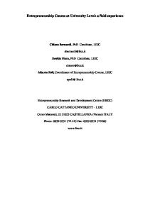
Buck Converter (DC-DC) The circuit of the buck converter (dc-dc) or step-down chopper using thyristor, with inductive (R-L) and battery (or back emf = E) load, is shown in Fig. 18.1. The switch in Fig. 17.1a is replaced by a thyristor here, where the components of the load, such as R, L & E, are also shown. The output (load) voltage and current waveforms for both (a) discontinuous, and (b) continuous conduction are shown in Fig. 18.2. LOAD
i0 +
A
R
K Switch G
Vs
+ V0
DF
L + E -
Fig. 18.1: Step-down chopper circuit using thyristor. Version 2 EE IIT, Kharagpur 3
Ig 0
t
io 0
t
v0 VS E 0
t
TOFF
TON T
(a) Discontinuous load current Ig
0
t
io Imax Imin 0 iT
iD
t
TON
TOFF
t
v0 VS V0 0 T (b) Continuous load current Fig. 18.2: Two modes operation of the chopper.
Version 2 EE IIT, Kharagpur 4
Maximum and Minimum Values of the Load Current The procedure for finding the maximum and minimum of the load current, assuming continuous conduction, is described. The operation of the chopper circuit has been discussed in the earlier lesson. There are two modes of operation. Mode 1 starts at t = 0 , when the thyristor is turned ON, with the diode, D F being OFF at that time, and continues till t = TON . During this time period, the load current increases. The induced emf in the load inductance L, is positive, i.e., having the same polarity as that of the input voltage, opposing it. Mode 2 starts at t = TON , when the thyristor is turned OFF by auxiliary circuit (not shown in Fig. 18.1), and the diode, D F turns ON at that time, as the load current starts decreasing, and the induced emf in the load inductance, L changes polarity, with the voltage across the diode now being positive. This continues till t = T , end of the time period. Then the cycle repeats. Mode 1: The equation for the load (output) current in the circuit during this time interval, 0 ≤ t ≤ TON is,
d i0 di +E or, VS − E = R i0 + L 0 dt dt The current is the load current, same as the source current during this time interval. The values of the load current ( i0 ) at t = 0 and t = TON , are I min and I max respectively. The expression for the V S = R i0 + L
load current is, i0 = A e − t / τ + B where A and B are constants, and time constant is, τ = L / R . At t = 0 , i0 = A + B = I min At t = ∞ , i0 = B = [(Vs − E ) / R]
So, A = I min − [(Vs − E ) / R] Substituting the values of A & B, the expression for the load current is, ⎡ (V − E ) ⎤ i0 = ⎢ s 1 − e −t / τ + I min e −t / τ ⎥ ⎣ R ⎦ At t = TON , i0 = I max . So,
(
)
⎡ (V − E ) ⎤ −TON / τ I max = ⎢ s + I min e −TON / τ ⎥ 1− e R ⎣ ⎦ ⎡ (V − E ) ⎤ 1 − e −TON / τ or, I max − I min e −TON / τ = ⎢ s ⎥ ⎣ R ⎦ This is the first expression obtained for mode 1 between I max and I min . Similarly, the second one will be derived for mode 2. Mode 2: The equation for the load (output) current in the circuit during this time interval, 0 ≤ t ≤ TOFF is, di di 0 = R i0 + L 0 + E or, − E = R i0 + L 0 dt dt It may be noted here that the time ( t = 0 ) is taken here from the start of mode 2, i.e., the end of mode 1. The current is the load current, and the current through the diode, D F during this time interval. The values of the load current ( i0 ) at t = 0 and t = TOFF , are I max and I min respectively.
(
)
(
)
The expression for the load current is, i0 = A e − t / τ + B . Version 2 EE IIT, Kharagpur 5
At t = 0 , i0 = A + B = I max
At t = ∞ , i0 = B = −(E / R )
So, A = I max + (E / R ) Substituting the values of A & B, the expression for the load current is, ⎛E⎞ i0 = −⎜ ⎟ 1 − e −t / τ + I min e −t / τ ⎝R⎠ At t = TOFF , i0 = I min . So,
(
)
(
)
⎛E⎞ I min = − ⎜ ⎟ 1 − e −TOFF / τ + I max e −TOFF / τ ⎝R⎠ ⎛E⎞ or, I max e −TOFF /τ − I min = −⎜ ⎟ 1 − e −TOFF / τ ⎝ R⎠ This is the second expression obtained for mode 2 between I max and I min .
(
)
From these two expressions, the currents, I max and I min are derived as, −T / τ ⎛ V ⎞ ⎡1 − e ON ⎤ ⎛ E ⎞ I max = ⎜ s ⎟ ⎢ −⎜ ⎟ −T / τ ⎥ ⎝ R ⎠ ⎣ 1− e ⎦ ⎝R⎠ T /τ ⎛ Vs ⎞ ⎡ e ON − 1⎤ ⎛ E ⎞ I min = ⎜ ⎟ ⎢ T / τ ⎥−⎜ ⎟ ⎝ R ⎠ ⎣ e −1 ⎦ ⎝ R ⎠
− RT / L ⎛ V ⎞ ⎡1 − e ON ⎤ ⎛ E ⎞ I max = ⎜ s ⎟ ⎢ − ⎜ ⎟ , and −R T / L ⎥ ⎝ R ⎠ ⎣ 1− e ⎦ ⎝R⎠ RT / L ⎛ Vs ⎞ ⎡ e ON − 1⎤ ⎛ E ⎞ I min = ⎜ ⎟ ⎢ R T / L ⎥−⎜ ⎟ −1 ⎦ ⎝ R ⎠ ⎝R⎠ ⎣ e
or, or,
Ripple content in the Load Current
As given earlier, the load (output) current varies between the maximum and minimum values ( I max and I min ). Therefore, the ripple content of the current is,
(
)(
)
(
)(
)
−T / τ − (T −TON ) / τ ⎤ ⎛ Vs ⎞ ⎡ 1 − e −TON / τ 1 − e −TOFF / τ ⎤ ⎛ V ⎞ ⎡ 1 − e ON 1 − e I max − I min = ⎜ s ⎟ ⎢ ⎥=⎜ ⎟ ⎢ ⎥ 1 − e −T / τ 1 − e −T / τ ⎝R⎠ ⎣ ⎦ ⎝R⎠⎣ ⎦ The above expression for ripple content is independent of battery voltage or back emf (E). Using the duty ratio, k = TON / T , the expression becomes,
(
(
)(
)
(
)
)
− k T /τ 1 − e − (1−k ) T / τ ⎤ ⎛ Vs ⎞ ⎡ 1 − e I max − I min = ⎜ ⎟ ⎢ ⎥, 1 − e −T / τ ⎝R⎠ ⎣ ⎦ its per unit value being, (I max − I min ) = ⎡ 1 − e − k T /τ 1 − e − (1−k ) T / τ ⎤ ⎥ (Vs / R ) ⎢⎣ 1 − e −T / τ ⎦
(
(
(
)(
)
)
)
The current ( Vs / R ) is taken as 1.0 pu (100%).
The Duty Ratio (k) for the Limit of Continuous Conduction The current waveforms for both continuous and discontinuous conduction are shown in Fig. 18.2. From the waveforms, it is observed that, for a low value of TON , or duty ratio, k , time period, T being kept constant, the turn-off time, TOFF is large. The output current, i0 may go to zero during this interval, depending on the circuit parameters. Therefore, the limit of continuous conduction is reached, when the minimum current, I min goes to zero. So,
Version 2 EE IIT, Kharagpur 6
T /τ eTON / τ − 1 ⎛ E ⎞ ⎛ V ⎞ ⎡ e ON − 1⎤ ⎛ E ⎞ or, =⎜ ⎟= g I min = ⎜ s ⎟ ⎢ T / τ = 0 − ⎥ ⎜ ⎟ eT / τ − 1 ⎜⎝ Vs ⎟⎠ ⎝ R ⎠ ⎣ e −1 ⎦ ⎝ R ⎠ where g = (E / Vs ) So, the duty ratio for limit of continuous conduction is, k ′ = (TON / T ) = (τ / T ) log e 1 + g eT / τ − 1 The output (load) current is continuous, if the actual duty ratio, k is more than the above duty ratio, k ′ , and it becomes discontinuous, if k is lower than the above duty ratio, k ′ .
[
(
)]
The Average Value of the Output Current The average value of the output (load) current for continuous conduction (Fig. 18.2b) is obtained as I av = (k Vs − E ) / R , as the average value of the output voltage is k Vs . This is, because the average value of L (di / dt ) over the time period, T is zero. This value can also be written as, TON TOFF ⎤ ⎛ 1 ⎞ ⎡TON ⎤ ⎛ 1 ⎞ ⎡TOFF ⎤ ⎛ 1 ⎞⎡ I av = ⎜ ⎟ ⎢ ∫ i01 (t ) dt + ∫ i02 (t ) dt ⎥ = ⎜ ⎟ ⎢ ∫ i01 (t ) dt ⎥ + ⎜ ⎟ ⎢ ∫ i02 (t ) dt ⎥ = ( I T ) av + ( I D ) av , ⎝ T ⎠ ⎢⎣ 0 ⎥⎦ ⎝ T ⎠ ⎢⎣ 0 ⎥⎦ ⎝ T ⎠ ⎢⎣ 0 ⎥⎦ 0 where i01 and i02 are the output (load) currents in the time intervals, TON < t < 0 and TOFF < t < 0 (the time ( t = 0 ) is taken as the beginning of OFF period (mode 2)) respectively. If the expression is derived by substituting the currents, i01 & i02 , its value comes out to be the same as
given earlier. The average values of the currents in the thyristor (I T )av and diode (I D )av , can also be computed by using the expressions for the currents separately. These two expressions are not included here, but are available in text book. All these values of the currents can also be obtained by using other procedure.
Fourier Analysis of the Output Voltage Waveform The output (load) voltage waveform for continuous conduction is shown in Fig. 18.2.b. This voltage is periodic in nature and also independent of the parameters of the load. The symbols, including some described earlier, are given here.
v0 = Instantaneous value of the output (load) voltage Vs = Source (input) voltage (constant) V0 = Average value of the output voltage T = TON + TOFF = Time period of the thyristor chopper (step-down)* TON = Time interval for which the thyristor is ON* TOFF = T − TON = Time interval for which the thyristor is OFF* f = 1 / T = Frequency (Hz) for the thyristor chopper (step-down)* ω = 2 π f = Angular frequency (rad/s) θ = ω t = Angle (rad) ω T = 2 π = Angle (rad) for time period, T a n & bn are the maximum values of the sine and cosine components of the harmonics of order n, present in the output voltage waveform respectively.
Version 2 EE IIT, Kharagpur 7
cn & θ n are the maximum value (amplitude), and phase angle, of nth harmonic component respectively. The relationships are cn = a n2 + bn2 , and θ n = tan −1 (bn / an ) , and the other relationships are an = cn cos θ n and bn = cn sin θ n . The rms value of nth harmonic component = cn / 2 * It may be noted that, when the thyristor (device) in the step-down chopper (Fig. 18.1), or buck converter (dc-dc), is ON, or conducting, the diode, D F is not conducting (OFF), and vice versa, i.e., when the thyristor (device) is OFF, or not conducting, the diode, D F is conducting (ON). The output (load) voltage waveform for one time period T , is, v0 = Vs for TON < t < 0 ; v0 = 0 for T < t < TON In terms of the Fourier components, the expression is, ∞
∞
n =1
n =1
v0 = V0 + ∑ (an sin nθ + bn cos nθ ) = V0 + ∑ cn sin (nθ + θ n ) where, ωT ωT ⎛V ⎞ 1 1 ON an = ∫ v0 sin (n θ ) dθ = Vs sin (n θ ) dθ = ⎜⎜ s ⎟⎟ cos n θ ∫ π 0 π 0 ⎝ nπ ⎠ ⎛V ⎞ ⎛ 2V ⎞ = ⎜⎜ s ⎟⎟ (1 − cos 2 π n k ) = ⎜⎜ s ⎟⎟ ( sin 2 ( π n k ) ) ⎝ nπ ⎠ ⎝ nπ ⎠ bn =
1
π
ωT
∫v 0
0
cos (n θ ) dθ =
1
π
ω TON
∫ 0
⎛V ⎞ Vs cos (n θ ) dθ = ⎜⎜ s ⎟⎟ sin n θ ⎝ nπ ⎠
0 2π k
2π k 0
⎛V =⎜⎜ s ⎝ nπ
⎞ ⎟⎟ (sin 2 π k ) ⎠
⎛V ⎞ ⎛ 2V ⎞ = ⎜⎜ s ⎟⎟ (sin 2 π n k ) = ⎜⎜ s ⎟⎟ (sin π n k ) (cos π n k ) ⎝ nπ ⎠ ⎝ nπ ⎠ ⎛ 2V ⎞ cn = ⎜⎜ s ⎟⎟ (sin π n k ) ⎝ nπ ⎠
θ n = tan −1 (cot π n k ) = (π 2) − (π n k ) The average value (dc) is V0 = k Vs , which has been derived in lesson #17 (module 3). Substituting the above values of cn & θ n , ∞ ⎛ 2V ⎞ v0 = V0 + ∑ ⎜⎜ s ⎟⎟ (sin π n k ) (sin (nθ + (π 2) − (π n k )) ) n =1 ⎝ n π ⎠ ∞ ∞ ⎛ 2V ⎞ ⎛ 2V ⎞ = V0 + ∑ ⎜ s ⎟ (sin π n k ) ( cos [ nθ − (n π k ) ]) = V0 + ∑ ⎜ s ⎟ (sin π n k ) ( cos[n (θ − π k )]) The n =1 ⎝ n π ⎠ n =1 ⎝ n π ⎠
maximum value of the fundamental component is, c1 = ((2Vs ) π ) (sin π k ) , and its phase angle (rad) is, θ1 = (π 2) − (π k ) . The magnitude of the maximum (or rms) value of the harmonic components decreases as its order (n) increases. ∞
∞
n =1
n =1
The rms value of the waveform is, Vor = (V0 ) 2 + ∑ (cn / 2 ) 2 = (V0 ) 2 + ( 12 ) ∑ (cn ) 2 The rms value is computed as, Version 2 EE IIT, Kharagpur 8
T
ON T ⎛1⎞ V0 r = ⎜ ⎟ ∫ (Vs ) 2 dt = ON Vs = k Vs T ⎝T ⎠ 0 It can be observed that the amplitude of the harmonic component depends on the order of the harmonic, n and also on the duty ratio, k. The maximum value of the nth harmonic component occurs, when sin (π n k ) = 1 , and its value (V) is,
2 Vs 0.637 Vs 2 Vs 0.45 Vs = , with its rms value (V) as = nπ n nπ n The value of the angle for the above condition, i.e., at which the maximum value of the magnitude of the nth harmonic component of the output voltage occurs, is, π n k = (4m + 1) (π / 2) = 2 π m + (π / 2) , or n k = (4m + 1) / 2 = 2 m + 12 or, ( 2 m + 0.5 ) Firstly, the average value or dc component and the rms values of all harmonic components, of the output (load) voltage, are computed as per the formula given earlier. It may be noted that, the rms values of only a few harmonic components need be computed, because the rms values decrease, as the order of harmonic increases (having an inverse relationship with it), as given earlier. Then, using the expression for the rms value, it (rms value) is computed. Finally, it can be checked from the expression for the rms value given earlier. As first example, the case of fundamental frequency ( n = 1 ) is taken up. The value of duty ratio is ( k = 0.5( 12 ) ) as ( k < 1.0 ), at which the magnitude of the output voltage is maximum at the above frequency. If the third harmonic ( n = 3 ) is chosen as another example, more than one value, in this case, three values of the duty ratio – ( k = 0.167 ( 16 ) & 0.833( 65 ) ), and also the previous value of ( k = 0.5( 12 ) ), as k < 1.0 , are obtained. If first two values of k are substituted, sin (π / 2) = 1 and the results obtained, using the ascending order, are sin (5 π / 2) = sin (π / 2) = 1 . But, if the value, ( k = 0.5( 12 ) ) is substituted, the results obtained is
cn = sin (3π / 2) = − sin (π / 2) = sin (−π / 2) = −1 . For this value in this case, 3π k = (3π / 2) or (− π / 2) . So, the set of values would be 3π k = (2 m π + (3π / 2)) or (2 m π − ( π / 2)) . Earlier, the value of cn is chosen as positive only, assuming that its angle would take care of the sign, i.e., for cn = +1 , θ n = 0° , and for cn = −1 , θ n = 180° (π ) . The angle ( θ n ) can be obtained by using the sign of two components, an & bn . But if a close look at the formula of cn is taken, it can have both +ve and –ve values, i.e., cn = sin (π n k ) = ±1 , being square root of a +ve quantity. The value would now be, n k = (4m ± 1) / 2 = 2 m ± 12 or, ( 2 m ± 0.5 ). So, for ( n = 3 ), three values of duty ratio, k as given earlier, are obtained. Similarly, for any other odd harmonic ( n = 2 m + 1 ), the duty ratios can be computed. It may also be observed that, for the duty ratio of ( k = 0.5( 12 ) ), the magnitudes of the output voltage at all odd harmonics are maximum. Now, for even harmonics ( n = 2 m ), the duty ratios for which the magnitude of the component of output voltage is maximum, are obtained. For second harmonic ( n = 2 ), two values of duty ratio obtained using the formula ( 2 k = 2 m ± 12 ) are,
k = 0.25( 14 ) & 0.75( 34 ) , as k < 1.0 . If these two values of k are substituted, the results obtained, using the ascending order, are sin (π / 2) = 1 and sin (3π / 2) = − sin (π / 2) = −1 . For fourth harmonic ( n = 4 ), the duty ratios obtained are,
Version 2 EE IIT, Kharagpur 9
k = 0.125( 18 ), 0.375( 83 ),0.625( 85 ) & 0.875( 78 ) , as k < 1.0 . Similarly, for the rms value of any other even harmonic to be maximum (highest), the duty ratios can be computed. To obtain the maximum value of average or dc component as per formula given earlier, the duty ratio is ( k = 1.0 ), it being an ideal one. In this case, the switch or the device is always ON in the time period ( 0 − T ), with the output voltage being constant, and also same as the average value, which is equal to the input (source) voltage. In the ideal case, no harmonic component, including fundamental one, is present in the output voltage. But the duty ratio in normal case, for buck converter (dc-dc) or step-down chopper (thyristor) circuit is ( k ≈ 1.0 ), due to the turn-off time requirement of the switching device used. For this case, the rms and average values are nearly equal, but the rms value is slightly higher than the average value. Both the above values are also nearly maximum. The ripple content is very low, with the rms values of the harmonic components, starting from fundamental, also being very low. All these can be checked from the formula. To eliminate a given harmonic or a set of harmonics in the output voltage waveform, the condition to be satisfied is, sin π n k = 0 , for which the value of the angle is π n k = m π , or n k = m . The case of even ( n = 2 m ) harmonics, starting from second ( n = 2 ), is taken up first. The duty ratio required is k = 0.5 , as k < 1.0 , for the elimination of second harmonic component. To eliminate fourth ( n = 4 ) harmonic component, two more values of duty ratio ( k = 0.25( 14 ) & 0.75( 34 ) ), including the earlier one ( k = 0.5 ), as k < 1.0 , are required. It may be noted that, with the duty ratio (k = 0.5) , all even harmonic components are eliminated. To make the average value or dc component zero (0), the duty ratio required is ( k = 0.0 ). But this is an ideal case, in which the switch or the device is OFF. In normal case, duty ratio required is very small ( k ≈ 0.0 ), due to requirement of both turn-on and turn-off times of the switching device used. For this case, the rms and average values are nearly equal, but the rms value is slightly higher than the average value. Both the above values are also nearly minimum. The ripple content is very low, with the rms values of the harmonic components, starting from fundamental, also being very low. All these can be checked from the formula. Now, the case of the elimination of odd ( n = 2 m + 1 ) harmonic components is described. If third ( n = 3 ) harmonic is to be eliminated, two values of duty ratios required are ( k = 0.333( 13 ) & 0.667 ( 23 ) ), as k < 1.0 . Similarly, for any other (odd or even) harmonic component to be eliminated, the duty ratios can be computed. The rms value of the nth harmonic component of the output (load) current is, c / 2 , where the load impedance for nth harmonic is Z n = R 2 + ( n ω L) 2 . In = n Zn As stated earlier, the rms value of the harmonic components of the output voltage decreases and also is inversely proportional to n, as the order of the harmonic (n) is increased. The impedance at the harmonic frequency ( n f ) increases, and also is nearly proportional to n, if the load resistance (R) is assumed to be much smaller than the inductive reactance ( 2 π n f L ), as the order of the harmonic is increased. So, the rms value of the nth harmonic component of the output current decreases at a faster rate, and also can be stated as being inversely proportional (nearly) to n 2 , with the increase in the order of the harmonic. If R is very small, and can be neglected, as compared to the inductive reactance, the rms value of the nth harmonic component of the output current is inversely proportional to n 2 , i.e. proportional to ( 1 / n 2 ).
(
)
Version 2 EE IIT, Kharagpur 10
The harmonic content of the output voltage waveform is the ac ripple voltage ( V r ), which can be easily computed as shown here, without computing the harmonic components. Its rms value is defined as Vr = (V0 r ) 2 − (V0 ) 2 , the other symbols having been defined earlier. The average value of the output voltage ( V0 ) is shown in Fig. 18.2b. If the X-axis is shifted to the average value, the remaining part is the ac ripple voltage, having both positive and negative values in a cycle. The expression for ac ripple voltage is obtained as, after substituting the expressions of two voltages given earlier, Vr = k (V s ) 2 − k 2 (Vs ) 2 = V s k − k 2
The ripple factor (RF) is defined as the ratio of ac ripple voltage to the average value, and is obtained as, V 1− k RF = r = V0 k It may be noted that the ac ripple voltage, in terms of rms values of all harmonic components, may also be computed as, Vr =
∞
∑ (c n / 2 ) 2 = n =1
∞
( 12 ) ∑ (c n ) 2 n =1
This value is same as computed by the expression given earlier. In this lesson ─ the second one in this module, the analysis of the analysis of the buck converter (dc-dc) or step-down chopper circuit, using thyristor as a switching device, with inductive (R-L) and battery (or back emf = E) load, is presented in detail The procedure for the derivation of following expressions ─ the maximum and minimum output (load) currents, assuming continuous conduction, the duty ratio for the limit of continuous conduction, the average value and the ripple factor, of the output current, and the harmonic components of the output voltage waveform, are described in detail. Starting with the next lesson ─ the third one in this module, the operation of the additional circuits needed for commutation in thyristor-based choppers, with relevant waveforms, will be taken up in detail.
Version 2 EE IIT, Kharagpur 11