Metacomet Emergency Communications Center (MECC) Request for Proposal Computer Aided Dispatch SOFTWARE Table of Content Section Number 1.0 2.0 3.0 4.0 5.0 6.0 7.0 8.0 9.0 10.0 11.0 12.0 13.0 14.0 15.0 16.0 17.0 18.0 19.0
Description Introduction, Legal & Contractual Requirements Introduction to Technical Specifications Call Handling/CAD Event Creation Dispatch Support Resource/Unit Management Call/Incident/Event Management Supplemental Resource Request & Tracking Incident Disposition Business Functions: CAD System Management System Function Reporting & Monitoring Interfaces Mobile CAD Functions Appendices for Technical Specifications Computer Hardware Training & Implementation System Acceptance System Maintenance Vendor Required Forms
Page 1 of 165
Page Number 2 18 21 46 59 71 88 91 95 109 119 124 142 149 154 157 158 158 158
1.0
INTRODUCTION, LEGAL AND CONTRACTUAL REQUIREMENTS
1.1 INVITATION The Metacomet Emergency Communications Center invites qualified vendors that manufacture and provide direct training, maintenance and support of their own Computer Aided Dispatch (CAD) software to submit responses at their own expense to this Request for Proposals (RFP). The responses received will enable the MECC to complete its selection process of CAD software to support its member’s Police, Fire, and related public safety operations. Interested firms are required to submit two (2) original and five (5) printed copies, as well as one copy via CD or USB drive (pdf or similar standard readable format), of its submission no later than Tuesday January 2nd 2018 at 2pm to the following office: Metacomet Emergency Communications Center c/o Town of Franklin Fire Department 40 W Central Street Franklin, MA 02038 The successful vendor shall furnish all application software, licensing, and related implementation services to make the proposed application software operational on the hardware and operating system(s) recommended by the vendor and provided by the MECC. All companies submitting proposals must be fully capable of providing installation, training, support, data conversion, and complete documentation for the software applications being proposed. Firms responding to this request should be of adequate size and sufficiently staffed to perform the assignment described above in a timely manner. The firm will be evaluated and selected based on the quality of the software and comprehensive approach to the various tasks to be automated, their technical competence, their capacity and capability to perform the work within the time allotted, and past record of performance which will be appropriately weighted in descending order of importance.
1.2 BACKGROUND AND SCOPE 1.2.1 Background The Metacomet Emergency Communications Center is located in Norfolk County in the southern part of the state. The MECC consists of the communities of Franklin, Norfolk, Plainville and Wrentham, and spans 74.8 square miles. The MECC has a population of approximately 66,000 (according to the U.S. Census Bureau, 2009 population estimates). In calendar year 2013, MECC Police agencies responded to nearly 65,000 requests for services with member fire agencies responding to approximately 15,000 emergency responses. The MECC currently will provide dispatch services through its Communications Center, which is currently under development. The center will receive all 911 emergency and non-emergency phone calls for Police and Fire/EMS services within the member communities, and is also responsible for processing and dispatching all Police and Fire/EMS calls.
Page 2 of 165
The MECC has established this RFP to procure a CAD system that will address the needs of the MECC including recommendations related to the required computer hardware to support the CAD Infrastructure.
1.2.2 The Integrated Computer Aided Public Safety Dispatch System (CAD) The CAD system shall consist of the following components and interfaces listed in order of current priority: • Call Handling • Dispatch Support • Resource/Unit Management • Call/Incident/Event Management • Supplemental Resource Request and Tracking • Incident Disposition • Business Function: CAD Administration • System Functions • Reporting and Monitoring • Interfaces including, but not limited to: o NG911 o Securus (PAMET) PoliceServer and FireServer o Alpine Software RedAlert o MA CJIS o EMD (APCO, PowerPhone, Priority Dispatch) o AmbuPro ePCR o Automated Secure Alarm Protocol (ASAP) • Mobile CAD Functions
1.2.3 Software Operating Systems The proposed CAD software shall be compatible with Microsoft Windows server and workstation Operating Systems.
1.2.4 Hardware (Servers, Workstation, etc.) Infrastructure (Infrastructure) Services Vendors shall include Workstation and Server specifications in their response. Workstations, Servers and local LANs will be supplied by the MECC. The selected vendor shall be responsible for the following Implementation Services: • Purchase Specifications for User Purchased Work Stations and Servers • Installation of all Server Hardware and System Software • Installation of all Application Software on the MECC provided Servers and Workstations • End-to-End Work Station to Server Testing and Certification of the System Operation
Page 3 of 165
1.3 VENDOR EVALUATION CRITERIA 1.3.1 Definition Proposals shall have each of the following requirements listed below to be considered “Qualified”. Note that the order in the list below is not prioritized. Vendors not able to provide evidence of the requirements may not be considered qualified to respond to this RFP and their Proposal may not be considered, at the sole discretion of the Metacomet Emergency Communications MECC. The Vendor shall provide a response to each of the following requirements in their Proposal Cover Letter signed by a person authorized to bind the vendor to a Contract.
1.3.2 Vendor Qualifications 1.3.2.1 Length of Business Service HIGHLY ADVANTAGEUOS - Vendors have a minimum ten (10) year track record of directly producing and delivering public safety software systems and a minimum six (6) years since the first production release of its Windows based CAD. ADVANTAGEOUS – Vendors have a minimum seven (7) year track record of directly producing and delivering public safety software systems and a minimum of five (5) year since the first production release of its Windows based CAD System NOT ADVANTEGOUS – Vendor has a minimum of 5 year track record of directly producing and delivering public safety software systems and a minimum of three (3) year since the first production release of its Windows based CAD System. UNACCEPTABLE – Vendor has less than 5 years of directly producing and delivering public safety software systems. 1.3.2.2 Sole Source Services HIGHLY ADVANTAGEOUS - The proposed systems shall consist entirely of Integrated Computer Software developed and supported by the Vendor. ADVANTAEOUS – The proposed system shall consist of integrated computer software developed by different vendors of the same parent corporation. NOT ADVANTAGEOUS – The proposed system consists of computer software developed and supported by two (2) vendors. UNACCEPTABLE – The proposed system consists of computer software developed and supported by more than two (2) vendors. 1.3.2.3 Systems Sales Volume HIGHLY ADVANTEGOUS - The proposed software systems shall be fully operational in a minimum of Twenty (20) separate Installations for public safety agencies.
Page 4 of 165
ADVANTEGOUS - The proposed software systems shall be fully operational in a minimum of ten (10) separate Installations for public safety agencies. NOT ADVANTEGOUS - The proposed software systems shall be fully operational in a minimum of five (5) separate Installations for public safety agencies. UNACCEPTABLE - The proposed software systems shall be fully operational in a less than five (5) separate Installations for public safety agencies. 1.3.2.4 Vendor Litigation HIGHLY ADVANTAEGOUS - Vendor shall be free of any litigation with private and public entities for seven (7) years. ADVANTAEGOUS – Vendor is free of any litigation with private and public entities for five (5) years. NOT ADVANTAEGOUS – Vendor is free of any litigation with private and public entities for three (3) years. UNACCEPTABLE – Vendor is free of any litigation with private and public entities for less than three (3) years. 1.3.2.5 Ongoing Support and Maintenance HIGHLY ADVANTAEGOUS - Vendor shall provide direct 24 x 7 x 365 maintenance and support using their own staff employees and not out-sourced resources. ADVANTEGOUS – The Vendor provides direct maintenance and support at least 16 x 7 x 365 using their own staff employees but out-source portions of the maintenance and support functions. NOT ADVANTEGOUS - The Vendor provides direct maintenance and support less than 16 x 7 x 365 using their own staff employees but out-source portions of the maintenance and support functions. UNACCEPTABLE - The Vendor outsources direct maintenance and support functions. 1.3.2.6 Unpaid Liabilities HIGHLY ADVANTAEOUS - Vendor shall not be in arrears or otherwise have any unpaid Federal and/or Commonwealth of Massachusetts employment, withholding, use and profit taxes, and have been compliant with said taxes for more than five (5) years. AADVANTAGEOUS – Vendor shall not be in arrears or otherwise have any unpaid Federal and/or Commonwealth of Massachusetts employment, withholding, use and profit taxes, and have been compliant with said taxes for more than two (2) years. NOT ADVANTEGOUS - Vendor is less than one year in arrears or otherwise have any unpaid Federal and/or Commonwealth of Massachusetts employment, withholding, use and profit taxes. UNACCEPTABLE - Vendor is more than one year in arrears or otherwise has any unpaid Federal and/or Commonwealth of Massachusetts employment, withholding, use and profit taxes. 1.3.2.7 Massachusetts DCJIS COMPLIANCE HIGHLY ADVANTAGEOUS - Vendor shall have successfully completed a full DCJIS Certification with the Commonwealth of Massachusetts. ADVANTAGEOUS – The vendor is presently in the DCJIS Certification process and anticipates certification on or before July 2015.
Page 5 of 165
NOT ADVANTAEOUS – The vendor is not presently in the DCJIS certification process. NOT ACCEPTABLE – The Vendor has not certified in any State’s Criminal Record System. 1.3.2.8 NIBRS Compliance HIGHLY ADVANTEGOUS - Vendor’s System shall comply with the most recent edition of the National Incident Based Reporting System (NIBRS). ADVANTAGEOUS – The vendor is presently in the National Incident Based Reporting System (NIBRS) compliance process for the most recent edition and anticipates certification on or before January 2015. NOT ADVANTAEOUS – The vendor is presently in the National Incident Based Reporting System (NIBRS) compliance process and anticipates certification after January 2015. NOT ACCEPTABLE – Vendor’s System does not comply with the National Incident Based Reporting System (NIBRS). 1.3.2.9 NFIRS Compliance HIGHLY ADVANTEGOUS - Vendor’s System shall comply with most recent edition of the National Fire Incident Reporting System (NIFRS). ADVANTAGEOUS – The vendor is presently in the National Fire Incident Reporting System (NIFRS) compliance process for the most recent edition and anticipates certification on or before January 2015. NOT ADVANTAEOUS – The vendor is presently in the National Fire Incident Reporting System (NIFRS) compliance process and anticipates certification after January 2015. NOT ACCEPTABLE – Vendor’s System does not comply with the National Fire Incident Reporting System (NIFRS).
1.4 VENDOR’S PROPOSAL TYPE AND REQUIREMENTS The proposal shall be as follows: •
Fixed Price Line Item Costs
•
System’s Line Item Costs in Paragraph 1.8 shall be guaranteed by bidder for twenty-four (24) months from date of contract award to enable phased purchase of Systems.
•
Delivery, Installation, Training, Warranty, Maintenance
•
Diagnostics and Support as specified herein.
•
Responses to all Requirements in Sections 3.0 and 15.0 below
1.5 VENDOR QUESTIONS AND RESPONSES Questions regarding this document should be referred to Gary M Premo, MECC Executive Director, 1-508553-5573. A summary of all questions and answers will be made available to each firm if they might influence the award of the contract. Vendors shall submit all questions in writing (email, fax or letter). Oral questions and/or subsequent responses from the MECC shall not be considered as relevant in the preparation of proposals. The MECC will respond to questions submitted at least one week before the due date. Responses to any question of significance will be sent to all vendors by e-mail.
Page 6 of 165
1.6 VENDOR’S PROPOSAL RESPONSE FORMAT AND CONTENTS Proposals must consist of the following Parts and in the specific formats detailed below. Proposals shall have a Cover Letter signed by a person authorized to bind the vendor. The Cover Letter shall also contain a Statement certifying compliance with Paragraph 1.4. The Statement shall certify: •
that the costs are warranted for twenty-four (24) months from contract award;
•
the MECC may, at its sole discretion, select any item(s) and related services for purchase(s) at the line item costs and reject all other line items; and
•
the MECC at its sole discretion, may choose not to implement multiple program phases and may elect to purchase any line items from a separate vendor.
1.6.1 Vendor’s Proposal Part 1. Management Summary The Management Summary shall be written for reading by non-technical personnel and contain a summary of the contents of the proposal including: •
Summarize your qualifications and experience for turnkey Windows SQL Systems to bid this RFP.
•
Brief Summary of the proposed Systems and Infrastructure and their integrated design features.
•
State the source, owner and copyright holder of the Systems proposed if the Systems were not developed by your employees.
•
List of all lawsuits and litigations, past and current with private and with public agencies.
•
Provide a D&B, Bank or equivalent financial reference(s) that will verify your financial stability over time.
1.6.2 Vendor’s Proposal Part 2. Corporate Data The following corporate information shall be submitted: •
Provide the type of organization (partnership, corporation, etc.) and state where organized and the names of all persons/entities having 10% or more ownership.
•
Provide a summary of your firm's experience in public safety on Windows based systems.
•
Describe your policy and program for 24 x 7 Maintenance and Support, Enhancement and New Release Cost, and Frequency of the Systems you propose. Describe all other levels of support you provide and related cost.
•
State the location(s) of the company office(s), representatives and maintenance personnel who will support the proposed system.
•
Provide a reference list of every public safety agency for whom you have installed the proposed systems to include the name, address, and telephone number of the contact person at each agency. The reference list must support the level of sales volume outlined in Section 1.3.2.3.
•
Provide a Reference List of public safety agencies for whom you have supplied infrastructure that includes Windows based, Citrix type servers for Work Station connectivity to the Server(s) SQL Database.
Page 7 of 165
1.6.3 Vendor’s Proposal Part 3. Proposed Computer Systems Software Description •
Provide a detailed description of the proposed Systems. Use the format of Systems detailed in RFP Section 3.0 through 13.0 to organize your detailed description of each and every System.
•
Provide a list of the features and functional requirements of RFP Sections 3.0 through 13.0 included in your bid prices that will require development in order to meet these specifications.
•
Provide a list of the features and functional requirements of RFP Sections 3.0 and 13.0 NOT included in your bid price that you will deliver at additional cost. Provide the cost of each Item on the List.
•
Provide a list of the features and functional requirements in RFP Sections 3.0 through 13.0 that you will not provide.
1.6.4 Vendor’s Proposal Part 4. Hardware Requirements Complete RFP Section 15.0 and include RFP Section 15.0 in your Proposal Part 4. State the expansion and upgrade capabilities of the proposed System and what additional computer hardware is required to support the System if a 100% growth is experienced in the activity detailed in Section 15.4.2.
1.6.5 Vendor’s Proposal Part 5. Detailed Compliance Response Attach a copy completed forms of RFP Section 19.1. For each Item where indicated by a "_____", enter in one of the following codes: CODES COMPLIANCE RESPONSE C - Requirement/Specification is met by the proposed Systems and is included in the bid. Feature will be demonstrated upon request. O - The requirement is fully met in the existing product, and that product is optional in this proposal. Related costs are included, and clearly identified in the pricing section. M - Requirement/Specification is not currently a feature of an existing product, and requires development; costs are included in the bid as indicated in your Proposal. Feature will be demonstrated prior to proposed delivery. E - Requirement/Specification will be delivered as a custom enhancement at an additional cost included in the bid as listed in your Proposal. X Requirement/Specification is not met by the proposed system and is not available as listed in your Proposal. A BLANK ENTRY WILL BE CONSIDERED AS "X".
1.6.6 Vendor’s Proposal Part 6. Maintenance, Support and Enhancements The Vendor’s policy and methods for Systems’ maintenance, agency support and enhancement should be described in this section. Items that should be described are: •
Telephone Support for the Systems 24 hours by 7 days
•
On-site support policy if problems arise due to the Systems
Page 8 of 165
•
Enhancement program anticipated for the Systems
•
Cost of enhancements
•
Cost of new software modules
•
Cost of new releases and anticipated frequency
•
Cost of manual updates
1.6.7 Vendor’s Proposal Part 7. Implementation Services Provide in detail the type and amount of services provided for: (1) Configuration, Generation and Installation (2) Training (3) Maintenance and Support Also provide a breakdown of the number of classes for each class type, the number of students to be trained in each class type, the length of each class type and the number of man days of training to provide the total number of classes as proposed in the Cost Form in Paragraph 1.7.2. The training requirements are as follows:
I. STAFF TRAINING System
Staff Type
Students
All Components CAD
System Managers Dispatchers
7 30
Students per Class
Class Length
# of Classes
II. POST TRAINING CUT OVER SUPPORT System Computer Aided Dispatch
Staff Type Dispatch
Staff Days 1
Proposals shall include the cost for each additional day for post-training cutover support, if determined to be required by the MECC.
1.6.8 Vendor’s Proposal Part 8. Implementation Schedule This section of the proposal should specify the time frame and Schedule of activities to be completed between the contract signing and the completed Systems. The desired time period for the entire implementation is twenty-six (26) weeks. Assume all systems are purchased at one (1) time for this purpose. Provide the following:
Page 9 of 165
•
A description of each program phase; Provide details of your approach for acquiring information on each agency and servicing their individual implementation requirements.
•
Estimated time for each phase.
1.6.9 Vendor’s Proposal Part 9. Cost Proposal (Sealed in separate envelope) •
The cost proposal shall be sealed in a separate envelope and labeled “COST PROPOSAL”.
•
Use the Cost Forms in Sections 1.7 to 1.10 for your proposed fixed price costs.
•
Detail any additional costs for items required to furnish a fully operational system meeting all relevant specifications herein that is not specified in Part 1.8. Failure to do so will not relieve you from the requirement to furnish said Items.
•
PRICES: In the event that there is a discrepancy between the unit price and the extended totals, the unit prices will govern. In the event there is a discrepancy between the price written in words and written in figures, the price written in word shall govern. After the proposal opening, a vendor may not change any provision of the bid in a manner prejudicial to the interests of the MECC or fair competition. Minor informalities will be waived or the vendor will be allowed to correct them. If a mistake and the intended bid are clearly evident on the face of the bid document, the mistake will be corrected to reflect the intended correct bid, and the bidder will be notified in writing; the bidder may not withdraw the bid.
•
In addition to the completed public safety dispatch software package, the vendor shall identify costs for the initial training for system administrators training, supervisors training and end user training. The length of each category of training shall be outlined
•
A vendor may withdraw a proposal if a mistake is clearly evident on the face of the proposal document, but the intended correct bid is not similarly evident.
•
MASSACHUSETTS SALES TAX: The MECC is exempt from the payment of Massachusetts Sales Tax. Identification number is 2061455360.
•
All costs as outlined above shall be submitted in a sealed envelope with the other proposal requirements outlined herein. The envelope shall be clearly marked – Cost Proposal.
1.6.10 Vendor’s Proposal Part 10. License/Contract Agreement Attach a copy of your software License Agreement(s) and contract terms for the System proposed post delivery annual maintenance and support and annual costs for all new enhancements to the System and new versions to be released of the System for Year 1 and Years 2 through 5. Such license agreement shall be appropriately modified so as to reflect contract requirements set forth within these specifications.
1.6.11 RULE FOR AWARD and CONTRACT The Contract will be awarded to the vendor the OWNER (Metacomet Emergency Communications Center) best determines meets the need of the MECC. The MECC reserves the right to reject any bid or portion of a proposal, to waive any informality in a proposal and to
Page 10 of 165
award contract by items or by total to the responsive and responsible vendor as shall be deemed in the best interest of the MECC. Award of this contract may be subject to an appropriation. The MECC reserves the right to request a vendor to maintain vendor records for six (6) years and to provide assistance with any future audit requirements. A Notice of Acceptance of the proposal will be mailed or furnished to the successful bidder within ninety (90) days of the public opening of the proposals. A MECC Contract and/or a Purchase Order will follow the written Notice of Award. The MECC reserves the right to randomly check references. Any vendor having two or more negative to fair reviews shall be considered non-responsive. The MECC has the right to reject the software if it does not conform to these specifications to the satisfaction of the MECC’s. Clauses requiring prepayment of any portion of the contract amount will be rejected. A Certificate of Vote signed by the appropriate person authorized to enter into a contract will be required at contract execution.
1.6.11.1 Short List The following criteria will be used to evaluate all proposals for inclusion of a short list of vendors that will be invited to present a demonstration, at their own expense, of their proposed Systems: •
Vendor qualification as outlined in Section 1.3.2.
•
Demonstrated ability of the proposed Systems to meet all the requirements and specifications in RFP Sections 3.0 and 13.0 and any additional features vendor proposes as detailed in Vendor's Proposal.
•
Evaluation of the vendors’ response to Section 19.1 Specification Response.
•
Verification of operational Windows based, multi-jurisdictional systems as specified herein.
•
Quality of the vendor’s track record in public safety for the type of systems detailed herein resulting from the MECC’s contacts with Vendor’s References in Vendor’s Proposal.
•
Proposed maintenance, support and enhancement programs.
•
Documented financial stability.
•
Proposed implementation program and time schedule.
1.6.11.2 Final Evaluation of Short List 1.6.11.2.1 Hands-on use of the Demonstration System - The most competitive proposals will be invited to provide on-site demonstrations of the proposed system(s) to individual stakeholders groups from each member community and staff type. Demonstrations shall be arranged after the opening of the RFP but prior to the opening of the cost proposal. Failure to complete a demonstration will eliminate a vendor from further consideration within the process. Vendor Demonstrations of Features and Functions as follows: •
Demonstration of proposed actual Systems’ features and their functional compliance with the technical requirements outlined herein
Page 11 of 165
•
Demonstration of other features, functions and transactions that enhance Systems’ reliability, performance and operator efficiency
•
Demonstration of efficiency of User navigation and interfaces to perform transactions
•
Other benefits offered by vendor
Vendor demonstrations will be completed and evaluated individually by the following Stakeholder Groups, which include but may not be limited to; •
System Administrators
•
Dispatchers
1.6.11.2.2 Visit(s) to MECC Selected Vendor’s Customer Sites Vendor shall supply the entire list of customer references (Section 1.3.2.3) including telephone numbers of contact person, for direct contact by the MECC. Representatives from the MECC, at MECC expense, may complete on-site visits for: •
Verification of integrated system performance at customer delivered systems
•
Verification of Vendor’s Proposal representations of features, functions, performance, reliability, etc., at customer delivered systems
•
Verification of Vendor’s delivery and support performance at customer delivered systems
1.6.11.3 Final Selection The final selection shall be based upon the final ranking of vendors from the process outlined in Sections 11.6.11.1 and 11.6.11.2. Once the ranking list has been established, the cost proposal for the top ranked proposal shall be opened and the MECC will enter into negotiations with the top ranked vendor for CAD Services. Vendor shall include their proposed cost in terms of overall cost, including five (5) years from the date of system acceptance (see Sections 1.7 through 1.12) in their cost proposal. Vendor shall also include methodology for establishing costs for continuing support and maintenance beyond five years from the date of system acceptance. Should this negotiation not result in the award of a contract the MECC will open the cost proposal for next highest ranked vendor and enter into negotiations with the second top ranked vendor for CAD Services. Should this negotiation not result in the award of a contract, the MECC will continue with the next highest ranked vendor and shall continue in this fashion until such time that a successful contract for CAD Services had been completed or the list is exhausted.
Page 12 of 165
1.7 SYSTEM’S LINE ITEM COST FORMS TEMPLATE 1.7.1 Systems Software Cost Form System License Fees
Installation Fees
Year 1 24x7 Maint. and Support
Total Year 1 Costs
Year 2 24x7 Maint. and Support
Total 5 Year Cost
CAD Mobile Data Police Interface Mobile Data Fire Interface Image Gateway AVL RMS Interface PD RMS Interface FD Project Management
1.7.2 Training Services Cost Form Class
# Days
Rate/Day
Total
Travel and Per Diem
Total Costs
Travel and Per Diem
Total Costs
System Manager Dispatcher
1.7.3 Hardware Infrastructure Certification Cost Form Class
# Days
Rate/Day
Total
Pre Installation Post Installation Project Management Total
Page 13 of 165
1.7.4 Hardware and System Software Installation Cost Form Class
# Days
Rate/Day
Total
Travel and Per Diem
Total Costs
Server Installation Client Installation Project Management Total
1.8 ADDITIONAL COST TO COMPLETE PROJECT FORM Provide an itemized list of any items not included above for each System by the Purchaser, and related costs that you deem necessary to provide a fully functional system meeting all of the requirements specified in RFP Sections 3.0 and 13.0. Failure to provide said list shall not relieve the Vendor from providing such items as necessary to a fully functional system meeting all of the requirements specified in RFP Sections 3.0 and 13.0 that the Vendor proposed to meet at the Fixed Price Purchase Costs proposed.
Item Costs Item
Description
Cost $ $ $ $
1.9 COMPUTER SYSTEMS SUMMARY FORM Assume all Systems purchased at one (1) time Item License Fee Installation Fees Maintenance & Support Fee – Year 1 Additional Costs
Fee $ $ $ Sub Total $ $ System Year 1 Costs
Maintenance & Support Fee – Year 2 thru 5 $ System 2 – 5 Year Costs
Page 14 of 165
1.10 COST TO ADD ADDITIONAL LICENSES CAD: $____________ per workstation for twenty-four (24) months. MCS: $____________ per Mobile for twenty-four (24) months.
1.11 CONTRACT CONSIDERATIONS 1.11.1 Equal Opportunity – Affirmative Action The successful firm shall comply in all aspects with the Equal Employment Opportunity Act. A firm with 15 or more employees shall be required to have an Affirmative Action Plan which declares that the contractor does not discriminate on the basis of race, color, religion, sex, national origin or age, and which specifies goals and target dates to assure the implementation of equal employment. A firm with fewer than 15 employees shall be required to have a written equal opportunity policy statement declaring that it does not discriminate on the basis of race, color, religion, sex, national origin or age. Findings of noncompliance with applicable State and Federal equal opportunity laws and regulations could be sufficient reason for revocation or cancellation of this contract.
1.11.2 Indemnification The MECC’s liability hereunder shall be limited to the amounts due the Contractor for services actually rendered. Payment shall be made on delivery of the purchased item, or upon completion of all work contracted for (whichever occurs later) and performed to the satisfaction of the MECC. The bidder shall defend, indemnify, and save harmless the MECC’s and its officials from all claims, demands, payments, suits, actions, recoveries, and judgments of every description, whether or not well founded in law, brought or recovered against it, by reason of any negligent act or omission of said bidder, his agents or employees, in the execution of the contract or in consequence of insufficient protection or for the use of any patented invention by said bidder, and a sum sufficient to cover aforesaid claims may be retained by the MECC’s from money due or to become due to the bidder under this contract, until such claims have been discharged or satisfactorily secured.
1.11.3 Insurance Requirements Prior to the execution of any contract, the Metacomet Emergency Communications MECC requires that any awarded contractor providing materials, equipment or services to the MECC, must provide to the MECC a certificate of insurance during the performance of the contract and for three (3)
years following acceptance of the product, keep in force at least the following minimum limits of commercial general liability insurance: Products/Completed Operations Aggregate $2,000,000 Personal and Advertising Injury $1,000,000 Each Occurrence $1,000,000 Coverage shall be written on a Commercial General Liability form. The policy shall be written on an occurrence form and shall include Contractual Liability coverage subject to the terms
Page 15 of 165
and conditions of the policy. The policy shall include owner as an additional insured as their interest may appear. COMMERCIAL AUTOMOBILE INSURANCE: The successful bidder shall, during the performance of the contract keep in force at least the following minimum limits of commercial automobile insurance: Each Accident:
$1,000,000
Coverage shall be written on a Commercial Automobile form. Any subcontractor to a contracted firm shall be likewise covered, and shall furnish certificates of coverage acceptable to the MECC before starting work. The awarded firm shall maintain professional liability insurance until the expiration of the statute of limitations. In the event there is no statute of limitations specifically applicable to this project, the awarded firm shall maintain coverage for a reasonable period after the date of substantial completion of the project as agreed to by the MECC and the awarded firm.
1.11.4 Invoicing and Payment Invoices shall be paid promptly by the MECC unless any items thereon are questioned, in which case payment will be withheld pending verification of amount claimed and the validity of the claim. Standard payment terms are Net 30 Days from receipt of properly executed invoice(s). If a vendor submits a proposal that includes payment schedules based on the completion of designated phases, those stages must be clearly outlined in your proposal. The MECC cannot make payments for "execution of contract" (payments due upon contract signing). The MECC has established a definition of acceptance in Section 17; firms submitting proposals shall include a designated stage for system acceptance using such definition, and payment relative to said stage shall be not less than 10%. Please note: the MECC will not consider proposals that offer alternative funding solutions (e.g. lease of systems). If your firm provides alternative funding solutions, such information shall be included with your proposal.
1.11.5 Non-Appropriation of Funds Please note that any contract executed by the Metacomet Emergency Communications MECC is subject to the appropriation of funds on an annual basis.
1.11.6 Non-Collusion The individual signing this submittal hereby declares that no person or persons other than members of his/her own organization are interested in this Project or in the contract proposed to be taken; that it is made without any connection with any other person or persons making a proposal for the same work and is in all respects fair and without collusion or fraud; that no person acting for or employed by the Metacomet Emergency Communications MECC is directly or indirectly interested therein, or in the supplies or works to which it relates or will receive any part of the profit or any commission there from in any manner which is unethical or contrary to the best interests of the Metacomet Emergency Communications MECC.
Page 16 of 165
An affidavit form (Appendix 19.2) is included with this document; bidders are required to complete the form and include with their bid response.
1.11.7 Governing Law Any resultant contract shall be interpreted and governed under the laws of the Commonwealth of Massachusetts, MGL Chapter 30(B).
1.12 ISSUANCE OF ADDENDA If it becomes necessary to revise any part of this request or if additional data is necessary to enable interpretation of provisions of this document, revisions or addenda will be provided to all prospective firms who receive this document. This document includes an acknowledgement page; this page must be faxed back to the Purchasing Department, to ensure proper notification of changes to the published documents. The Metacomet Emergency Communications MECC does not assume responsibility for any vendor that does not receive revisions or addenda, where the vendor has not acknowledged receipt of any portion thereof.
Page 17 of 165
2.0 2.1
INTRODUCTION TO TECHNICAL SPECIFICATIONS CAD Systems
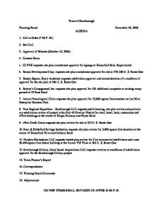
A CAD system is the principal application used by public safety agencies to manage law enforcement, fire, and EMS incidents from the initial time an incident is reported to the conclusion of the incident. CAD is also used to track the status and location of resources, and for post-incident analysis of the response. A CAD system consists of either a single software application or a suite of integrated software packages used to initiate a public safety call for service (CFS) record, to dispatch, to maintain the status of responding units and resources in the field, and to generally manage the incident. It is typically used by emergency communications dispatchers, call takers, and telecommunicators in public-safety communications centers. Modern CAD systems are usually extended out to field personnel (responders) through their mobile data computers (MDC), remote connections, and/or other devices, such as personal digital assistants (PDA). CAD systems are used to accomplish many tasks related to the tracking of public safety incidents and the assignment, allocation and deployment of law enforcement, fire, and EMS personnel. As well, CAD systems are designed and configured to meet the operational and administrative needs of the public safety agencies. The CAD system is one of the most important tools utilized by a Public Safety Answering Point (PSAP). All reported incidents are entered, dispatched, managed, and tracked via the CAD system, making it a mission critical system. The lives of citizens and public safety personnel heavily depend on the CAD system consistently performing at its maximum operational effectiveness and reliability. Although a CAD system is just one of many systems that public safety departments utilize (see Figure 1 below), it is often considered the heart of public safety operations. Following are a few of many reasons for this: 1) Virtually all law enforcement, fire, and EMS incidents flow through the CAD system. 2)
Many public safety technology systems, such as 9-1-1, Geographic Information System (GIS)/Mapping, Automatic Vehicle Location (AVL), MDCs, Records Management Systems (RMS), and data mining applications are either an integrated part of, or are interfaced with, the CAD system.
3)
The CAD system is often the primary connection CAD users have to external systems, including neighboring and remote CAD systems, regional RMS, and state and federal criminal databases such as the Department of Motor Vehicles (DMV), Nlets (The International Justice & Public Safety Network), the Federal Bureau of Investigation National Crime Information Center (FBI NCIC), and the FBI’s National Data Exchange (N-DEx). 4) The CAD system is the primary tool used for public safety resource management.
CAD systems consist of several modules that provide a variety of services and functions at multiple levels within a public safety communications center (see Figure 2 below). These services include call input, call dispatching, call status maintenance, event notes, resource unit status and tracking, and call resolution and disposition. Further, CAD systems include interfaces that permit the software to provide services to dispatchers, call- takers, and field personnel with respect to control and use of radio and telephony
Page 18 of 165
equipment, Emergency Medical Dispatch (EMD), external RMS, and other internal and external systems, as well as other services and functions.
FiGURE 1. CAD SYSTEM FUNCTIONAL COMPONENTS
2.2
Notes to the Reader
Organization of Each Functional Section and Sub-Sections Sections 2.0 through 11.0 in this document each correspond to a main CAD functional area with the associated functions for each. These include: Use of “Shall” and “Should” The use of the word shall refer to a mandatory requirement, whereas the word should means that a specification is merely requested.
Page 19 of 165
Icons Icons are provided below the section title for each function included in the document. These icons are intended to provide a visual “flag” as to which service (Law Enforcement, Fire, EMS) the specification commonly applies to. Law Enforcement
Fire
EMS
Requirements The specifications presented in this document are representative and not intended to be allinclusive. Where a vendor exceeds the requirements of this specification they shall outline such on a separate sheet, outlining the require section/subsection and an overview of how their product exceeds the requirement as requested. Generic / Provider Agnostic The information presented in this document is intended to be generic rather than favoring one particular system or approach over another. The document defines what is to be accomplished versus how it should be accomplished. These requirements were developed to depict current, basic functionality that a new CAD system shall contain. Incidents/Events/CFS For the purposes of this document, an incident is a real world event that results in a notification being made to a PSAP. An incident could range from something as minor as a parking complaint, as routine as an officer initiating a traffic stop, or as major as a natural disaster or terrorist attack. Once the PSAP has been notified, the CAD operator creates a CFS, CFS event, or CAD event in the CAD system for the purpose of tracking the incident. The CFS or CAD event is the CAD record of an incident occurring in the field. A single incident can result in multiple CFS and/or events. All pertinent information relating to the actions taken by one or more communications centers is accomplished through one or more CFS event records. Generally, a CAD CFS event record is created when an incident requires the dispatch of one of more resources, including officer-initiated activities.
Page 20 of 165
3.0
CALL HANDLING / CAD EVENT CREATION
The CAD handling and event creation process consists of the PSAP being notified through a variety of sources of the need for assistance: • • • •
Receiving a telephone call, electronic notification, radio alarm signal, radio request; Obtaining sufficient and accurate information from a reporting party or electronic device to determine the location and event classification; Determining if the incident being reported is a duplicate of an incident in progress; and, Creating or updating the CFS in the CAD system.
The system shall provide users an automated process to verify, analyze, classify, and prioritize CFS before electronically routing them to dispatcher(s) or to other appropriate destinations, such as a telephone reporting unit. CFS may also be generated by units in the field via their MDC or generated by a monitoring device such as an accident detection unit, intrusion alarm, or personal health monitor and transmitted to the appropriate communications center via a data interface. Operational Examples A traffic accident occurs at a busy intersection and it is obvious to witnesses that injuries are severe. Smoke is emanating from one of the involved vehicles. Information is gathered from the first 9-1-1 caller and entered into the CAD system using a CAD event data entry screen. The call taker enters the event’s location into the CAD system and selects the appropriate event type based on information provided by the reporting party. The call taker enters the event so the CFS can be simultaneously sent to the appropriate law enforcement, fire, and EMS dispatch positions. Dispatcher positions are now able to immediately assign and dispatch emergency resources to the event by using pre-determined response plans, which are based on the event’s location and type. Meanwhile, the call taker continues to gather additional information from the reporting party and updates the CFS record. Each involved dispatcher receives notification that the CFS has been updated and is able to view the updates. Other people may dial 9-1-1 or a non-emergency number to report the same incident, or an accident detection device on one or more of the involved vehicles may also report the accident. As call takers begin the data entry process, the CAD system alerts them that a CFS is currently active for the same location and has a similar event type. The call taker can then determine whether the new reporting parties have additional information that was not reported by the initial reporting party. A new CAD event entered but later determined to be a duplicate of a CAD event already in progress can be flagged in the CFS record as a duplicate of the original incident. Pertinent details gained from these new reporting parties can be provided as updates to all involved dispatchers and field responders.
3.1
Call Handling
A reporting party initiates the CAD process by reporting an incident to a public safety answering point. Reporting parties consist of citizens, electronic devices (e.g. burglar or fire alarm), agency staff, and other agencies requesting services from the agency or giving notification of events or activities of concern. An incident notification may come from many different points of origin, such as alarm systems, personal monitoring devices, Enhanced 9-1-1 (NG9-1-1) systems, direct calls (10- digit numbers), walk-ins, CAD-to-CAD interfaces, two-way radios, and other Webbased systems.
Page 21 of 165
The service requested by reporting parties can consist of both emergency and non-emergency priorities. Call taking (handling) consists of: • • • •
Receiving the call or other notification; Obtaining sufficient information from the reporting party; Determining if the event reported is a duplicate of an incident in-progress; and, Recording or updating the CFS in the CAD system.
The call taker may also apply procedures and guidelines to verify, analyze, classify, and prioritize the CFS prior to routing it to appropriate dispatch positions. A CFS may also be generated by a unit in the field when a field unit encounters a new incident or when the field unit self-initiates an activity. The unit can contact the dispatcher or the call taker, or may electronically create the CFS using their MDC or other device with a CAD-accessible application. A CFS may be forwarded to a telephone reporting unit or be initiated by the telephone reporting unit. A telephone reporting unit typically handles non-emergency CFS in response to incidents that do not require a response by field resources. A CFS may be created for future scheduled events, such as parades, organized demonstrations, and large concerts. Requirements In order to support the Call Handling function, the CAD system: • Shall import and attach/append, automatically upon user command, automatic number information (ANI) and automatic location information (ALI) to a CFS. • Shall import (automatically) external alarm data that conforms to the APCO/CSAA (Central Station Alarm Association) published ANS; and, Shall generate a CFS upon receipt of a new alarm notification. •
Shall import (automatically) a CFS received from another CAD system.
•
Shall import (automatically) a CFS generated on an MDC.
Relevant Technical Standards / Guidelines •
3.2
None.
CAD Incident / Event Types
CAD incident/event types describe the nature of “what is happening” at an incident. They are codes that describe the various types of incidents that can be received by a PSAP. Typically, each incident type is associated with a specific response plan that establishes the number and types of resources initially required for mitigating the incident, dispatch position(s) responsible for the incident, and its default priority. CAD systems should allow specific instructions to be associated with CAD event types that may, for example, display specific questions regarding the nature of the incident (type) thereby assisting in a better classification of the incident. If present, CAD should display the special
Page 22 of 165
instructions after the event type is entered. The special instructions can be presented to the CAD user as text, drill down trees, or other similar methods. If a tree format is used, then the selected responses should be stored in the event history. Special CAD Incident Types A CAD incident type (nature code/event type) can initiate multiple CFS events if the incident type is determined to require a multi-agency response (e.g. an accident with injuries in which law enforcement, fire, and EMS must respond). Available options for dealing with this situation may include creating a separate, but linked, CFS event record for each required service agency, or creating one CFS event record that handles all of the responses. The selected method should be compatible with the local agency’s requirements. Although APCO, National Emergency Number Association (NENA), and other national and international public safety organizations are moving towards a national set of defined incident types, CAD systems should allow the local agencies using them to define and update their own sets of incident types. CAD systems should also allow agencies to associate incident types with specific dispatch plans and priorities. CAD systems should allow the local agencies that create their own sets of incident types to map them to the appropriate ANS incident types so that incidents can be more easily shared across agencies and CAD systems. Some examples of typical user-definable specialized incident types include hazardous materials, weapons of mass destruction (WMD), decontamination, bomb threat, and civil disturbance. Advised Events CAD systems should provide users the ability to record information from citizens about particular situations or events that do not require the dispatching of any public safety resources. These incidents should create CAD event records that are recorded and that can be easily retrieved from the system/event history files for later access and analysis. CAD systems should also be able to route advised events to pre-defined workstations, user groups, and/or a pre-determined set of locations, such as fire stations, based on the dispatch plan associated with the incident’s event type and location. CAD systems should support the capability of pre-determining that a specific event type will automatically become an advised event with specific notification/routing characteristics. In addition, a CAD user should be able to designate an event as an advised event during event entry. Advised events should be able to initiate agency-definable notifications. Make Paper Events 3 CAD system users should be able to enter an event that bypasses dispatch, but that assigns a resource with a disposition and closes the event upon entry with the user designated disposition. This “Make Paper” event should be included in the location history of the location where the event occurred. It should be possible to associate “Make Paper” events with a logged-on employee’s identification. A “Make Paper” event identifier in the event history should differentiate it from normal events. Requirements In order to support the CAD Incident / Event Types function, the CAD system: •Shall allow for system administrator-defined CAD incident types or nature codes.
Page 23 of 165
• Shall allow system users to modify the incident type and provide new/updated response plan information/suggestions based on the new incident type. • Shall provide the capability to create an event, assign a unit, and close the event with a disposition without going through the dispatch process steps. • Shall provide the capability to flag a CFS as an “Advised Event” separate from the incident type/nature code. Relevant Technical Standards / Guidelines • APCO 2.103.1-201x: Public Safety Communications Common Incident Types for Data Exchange (in development) – http://www.apco911.org/911-resources/standards/apcostandards-in- progress.html. 3
Also known as a “Log Only Event” by some agencies.
3.3
Update Call for Service Event Data
As new information about an incident is obtained from the reporting party or other reporting sources (e.g. field responders reaching the scene, monitoring devices, duplicate calls), CAD systems must provide a mechanism for entering the new information into the CFS record. New information that surfaces about an open incident must update the CFS as new information becomes available. Multiple callers provide potential witnesses to the incident and may provide additional or supportive information. This may result in the reclassification and/or reprioritization of the incident. Communications center personnel must be able to enter narrative data and the reporting parties’ information into the CFS record at any time before and after the event is closed. Requirements In order to support the Update Call for Service Event Data function, the CAD system: • Shall enable the user to enter supplemental (new) information into the CFS event record of one or more user-specified CAD events. • Shall display a notification of the event update at each appropriate CAD position whenever an active event record is updated, as determined by the system’s configuration. • Shall create an automatic time/date stamp for every transaction related to an event, and Shall store the responsible operator’s identification (ID), the console ID, and the nature of the change. • Shall add audit records to the event history or store audit records in the CAD system’s audit log file in chronological order; and, Shall provide a complete historical audit of all event activity (e.g., comments, unit status changes, license plate information, field updates). • Shall store old entry information, with the appropriate date, time, operator ID, and console stamps if the new entry replaces existing information in the event record.
Page 24 of 165
• Shall enable the audit information to be retrieved and printed in both summary and detailed formats when incident information is displayed. • Shall create a permanent audit trail for all information recorded related to an event, whether or not that information is later modified or deleted. • Shall support ease of entry for supplemental event information and changes to existing event information. • Should allow the user to display a supplemental data entry screen by specifying either the event number or a unit assigned to the event. • Should allow the user to display a data entry screen to change information previously entered into a CAD event by specifying either the event number or a unit assigned to the event. • Shall provide agency-definable visual and audible alerts to notify field units and other appropriate CAD system users, including users of systems interfaced to CAD such as Mobile Data Computers, of event changes and supplemental information. • Shall allow the user to add supplemental information and/or change active events. • Shall allow the user to update any field in the CFS event record (except user-designated fields, such as application-generated times and date stamps, operator identification information, ANI/ALI information, and CAD position that completed a CAD transaction). • Shall document all changes and supplemental information in the event history. • Shall provide an event update/change data entry screen. • Shall allow the user to update or change a unit’s most recent event by entering the unit’s identification or any unit that is currently assigned. • Shall require confirmation from the user when attempting to update any field in a closed event. • Should provide the user with acknowledgment that an update to a CAD event record was successfully completed. • Shall allow the user to supplement and/or change active events. • Shall allow the user to supplement and/or change any field of a closed event without having to change the state of the event(except user-designated fields, such as applicationgenerated times and date stamps, operator identification information, ANI/ALI information, and CAD position that completed a CAD transaction). Relevant Technical Standards / Guidelines •
3.4
None.
Determine Dispatch Need For every CFS, a decision must be made as to whether to dispatch resources or to close the CFS with an explanation of why no resources were dispatched.
If the information gathered indicates that a public safety response is not warranted, based on local policies and protocols, then the CFS should be closed with a disposition code and, where
Page 25 of 165
appropriate, narrative/comment information that explains why no resources were assigned to the event. If a decision is made that resources are required, then the collected information must be routed to a dispatch position to begin the resource assignment process. As noted throughout this document, these two functions (call taking and dispatch) can be performed by the same person. Requirements In order to support the Determine Dispatch Need function, the CAD system: • Shall provide the capability to close out the CFS record without assigning a resource, if it is determined that a CFS does not require the assignment of a resource(s). • Shall allow the user to append a disposition code and comments to events that are not assigned any resources. Relevant Technical Standards / Guidelines •
3.5
None.
Utilize Incident Disposition
An incident is normally considered closed when all assigned units have completed their assignment and have cleared from the incident. Depending on the agency’s standard operating procedure (SOP), the primary unit, a dispatcher, or both must be able to close the CFS and append a disposition code/status to the incident’s record. Dispatchers are typically notified of changes in status and locations of the resources that they are controlling, either via radio (voice) or MDC transactions. Unit status and location status changes completed via MDC transactions should automatically update the CAD system. The CAD system should automatically close an event if the received MDC data indicates that the incident is complete by determining that resources are no longer assigned to the incident. Prior to closing the call, a specific closing disposition must be added to the CFS record if required by agency policy. Typically, the incident’s final (closing) disposition is provided and/or entered by the incident’s primary unit. Depending on agency SOPs, other assigned resources may also be required to provide one or more dispositions when clearing from their assignments. When a CAD event is closed, and at other times during the incident, CAD must be able to automatically transfer key event information to one or more associated RMS. Any updates made by CAD users on reopened incidents should also be automatically transferred to the appropriate RMS, subject to agency policies (see Section 11.1 Essential Interfaces). When a duplicate event is identified, CAD users must be able to close the duplicate event with a disposition indicating that it is a duplicate event. CAD users must be able to merge any new information contained in the duplicate event into its equivalent main CAD event. The CAD system must automatically cross-reference the main and duplicate events before closing them so that either one can be retrieved, if necessary. Requirements In order to support the Utilize Incident Disposition function, the CAD system:
Page 26 of 165
• Shall allow the user to enter one or more dispositions, as dictated by agency policy, when a CAD event is closed. • • Should provide the capability for a mobile unit to enter one or more dispositions when clearing from a CAD event. • Shall allow the system administrator to define disposition codes. Relevant Technical Standards / Guidelines •
3.6
None.
Assign Incident Classification and Priority One of the key pieces of information utilized in CFS event creation is incident/event classification. This process will determine the appropriate dispatch and response needs.
A list of pre-defined incident type codes created by the system administrator is presented to CAD users to allow the most appropriate incident type to be selected. Each of these codes has a default priority assigned based on agency, geo-area, response plans, and deployment plans. The priority and response criteria can be specified for each agency, based upon individual policy. Upon completion of this task, a type code is assigned to the incident. Based upon information gathered, the incident classification process should be able to be upgraded or downgraded as the incident details depict. This step should be able to create a CFS event for each response agency among MECC communities with one entry. Requirements In order to support the Assign Incident Classification and Priority function, the CAD system: • Shall enable CAD users to select the appropriate incident/event type from a pre- defined list of codes based upon information received from reporting party. • Shall provide, in a multiple dispatch agency or jurisdiction environment, the ability to create multiple CFS events with a single CFS event entry (e.g. a shooting incident type would create a law enforcement, EMS, and possibly a fire event). • Shall provide the ability to generate a CFS event with only the location and incident type code entered. • Shall allow the user to upgrade or downgrade the CFS event to fit the reported event by changing the priority for the event. • Shall allow the user to utilize incident screening menus, such as a drop-down menu, to assist in determining the appropriate incident/event type code.
Page 27 of 165
• Shall allow the user to interrupt the CFS event creation process and save entered information, sometimes known as call stacking, to process a higher priority incoming incident. • Shall provide a warning notification of the held CFS event generated at an administratorconfigured time. Any position can review current CFS events, retrieve a partial CFS record, and complete the CFS event entry. • The number of partial CFS events that can be stacked by a single position Shall be an administrator-configurable system parameter. • Shall provide the ability to override the event priority for each agency. • Shall provide the ability to create and maintain incident screening menus or prompts that can be used to aid the call taker in determining the appropriate incident/event type code. • Shall provide the ability to save one or more partially completed CFS events in order to enter a higher priority incident, keeping all entered data intact. • Shall provide a warning (visual and/or audible) that a partially completed CFS event has been held for an administrator-defined period of time. • Shall provide the ability to view a summary of all system-wide, partially-completed CFS events being held and awaiting completion. • The summary Shall include, at a minimum, the position and user ID that placed the CFS event on hold and the elapsed time that the CFS event has been on hold. • Shall provide the ability to redirect assigned resources to a higher priority CFS event based on agency defined criteria. • Shall store all active and partially completed CAD events in system administratorconfigurable queues. • Shall allow CAD users to be able to select a partially completed CFS event from a CAD event queue and complete the CFS entry process. Relevant Technical Standards / Guidelines •
3.7
None.
Check for Duplicate Incidents Multiple incident notifications for the same incident may be received via many sources; for example:
• A traffic accident is witnessed by two or more motorists, an on- duty public safety responder, and by a Telematics 4 Service Provider (TSP); or, • A fire alarm is reported from an electronic monitoring system and, at the same time, a witness calls 9-1-1 reporting smoke coming from a business. CAD systems must be able to automatically evaluate an entered incident’s location and call type to determine whether it is a duplicate or new CAD event. The duplicate event detection process must be
Page 28 of 165
based on pre-determined geographic search parameters that include exact street addresses, street addresses within the same block, system administrator-configurable radius searches around the geocoordinates of the incident location, and/or other system administrator-defined search parameters. The CAD system should analyze all open events, as well as closed events, within an administratorconfigurable time period. Upon indication by the CAD system of a possible duplicate event, CAD system users must be able to evaluate the duplicate event detection information presented by the system to make the final decision of whether new incident notifications are duplicates of a previously entered CAD event.
4
Telematics is the blending of computers and wireless telecommunications technologies, ostensibly with the goal of efficiently conveying information over vast networks to improve a host of business functions or government-related public services. The term has evolved to refer to automobile systems that combine global positioning satellite (GPS) tracking and other wireless communications for automatic roadside assistance and remote diagnostics. The telematics industry is not limited to automotive applications. Other applications are being studied or developed for monitoring water and air pollution, for medical informatics and health care, and for distance learning.
If the new incident is determined to be a duplicate, then CAD users should be able to add any new information contained in the current CFS entry screen and link the new information to the primary active CFS record without having to re-enter it. Based on agency policies, events linked to the primary active CAD event record should be automatically updated by the CAD system to contain the newly added information, and CAD users should be alerted that new information is available in the linked call’s event record. If the primary event record associated with a duplicate CAD event is closed, then CAD users should be able to add new information to the closed event record, possibly with a reminder to the user that the record was closed. If the new information requires a dispatch of public safety resources, then CAD users must be able to re-open the CFS event, add the new information, and route the CFS back through the dispatch process. Requirements In order to support the Check for Duplicate Incidents function, the CAD system: • Shall store all transactions resulting from the duplicate event detection process in the system’s audit log. • Shall identify during the creation of a CFS event whether the event is a potential duplicate of an active CAD event or an event recently closed; and, Shall notify the call taker of the results. • Shall check, as configured by the system administrator, by exact street address, street address block range, or geo-coordinates, the location of each new CFS event to determine whether another event exists. • Based on system parameters set by the administrator, either all matching events shall be presented to the user, or only those events with the same or similar nature code. • Shall check, as configured by the system administrator, within a pre-defined search radius of the location of each new CFS event, to determine whether another event exists within the search radius. • Based on system parameters set by the administrator, either all matching events shall be presented to the user, or only those events with the same or similar nature code.
Page 29 of 165
• • Shall present the user with the following information for each potential duplicate event if potential duplicates are located: o o o o
Incident ID Type of incident Location of the incident Status of the incident
• Shall allow the user the ability to create a new CFS event and link the event to the primary event record; or, to merge any new information contained in a duplicate event into the main event record associated with the identified duplicate CAD event. • Shall allow the call taker to re-open closed CAD events that are duplicates of a new event, add additional information to the re-opened CAD event records, and, if necessary, re- route them back through the dispatch process. • Shall, based on agency policy, restrict users from changing or deleting any previously entered data contained in re-opened closed CAD events. • Shall cross-reference duplicate events to the primary event records, leave both events open, or abandon processing of the duplicate event. Relevant Technical Standards / Guidelines •
3.8
None.
Incident Information
There are several means for receiving requests for assistance from the public: telephone, from a field unit via radio or MDC, through a CADto- CAD interface, via telematics monitoring devices, and directly from third- party alarm-monitoring centers. Most, if not all, of the information received from the public or from an interfaced device (e.g. CAD-to-CAD, alarm monitoring) needs to be captured in the event’s CAD record. This section deals with incident information that needs to be captured by CAD. Call takers acquire incident information (e.g. the reporting party’s name/address/phone number, incident location, narrative details, incident location, affected business name, incident location directions) from reporting parties and automated devices. Depending on how the reporting party contacts the PSAP, some of this information, such as ANI/ALI, is available through digital displays and interfaces. Either before being entered into CAD or immediately after (if automatically loaded into CAD via an electronic interface), all of this information must be verified and validated. CAD systems must provide an ergonomically structured, easy flowing graphical user interface (GUI) that can be used to enter and/or validate incident-related information. Although call takers need to be able to enter information into CAD in any order, the location, nature of the incident, and caller phone number are prioritized: call takers typically interact with reporting parties in a structured manner that enables obtaining these three critical components of the incident as quickly as possible. Once these critical components are obtained and verified, and
Page 30 of 165
depending upon the priority of the incident, CAD must be able to route this partially completed event record to appropriate dispatchers so that resources can be assigned and dispatched while call takers continue collecting other incident information from reporting parties. CAD users (e.g. telecommunicators, dispatchers, call takers, supervisors, and even first responders) must be able to enter narrative information (comments) into the CAD event record. Since more than one CAD user and first responder could be working on a single CAD event, and since dispatchers and first responders need to be aware of all recently entered/updated information, CAD must support the continuous and simultaneous entry of comment information into the CAD event record by multiple users. As comments are entered into CAD, they must be almost instantaneously available to all staff handling the event. Structured, drop-down, data entry fields should be available for those emergency event-related data that lend themselves to standardization (e.g. height, weight, priority, nature code/type, incident location). Free format fields (e.g. text comments and descriptive fields) should also be available as needed. CAD system users should be able to enter text in a non-case sensitive format, as well as to use search, replace, spellcheck, and other text editing features when appropriate. CAD systems should provide the ability to enter an unlimited number of comments/narrative details. As NG9-1-1 capabilities become more widespread, CAD systems should be compatible with handling NG9-1-1’s enhanced media content (e.g. pictures, text, streaming audio and video, and telematics data streams), including the display, storage and retrieval of this information from the CAD system and/or an interfaced recording device/system. Sample Requirements
Requirements In order to support the Incident Information function, the CAD system: • Shall provide the ability to create a CFS with minimum required fields (e.g. location and event type). • Shall provide the ability to dispatch once location and nature are obtained. • Shall provide the ability to alter/augment event as further information is obtained by the call taker. • Shall include an automated connection/interface to the 9-1-1 telephone system to use ANI/ALI data to populate the incident entry screen form. • Shall provide the ability to use ANI/ALI data to assist with CFS entry. • Shall provide the ability to enter unlimited narrative with text wrap-around feature. Relevant Technical Standards / Guidelines •
3.9
None.
Determining Capture Locations In many instances, call takers have access to callback numbers and call origination locations (ANI/ALI) via the NG9-1-1 system. If not, then the incident location must be elicited from the caller. In some incidents,
Page 31 of 165
the caller’s location is not the location of the incident (e.g. fire across the street, accident report from a moving vehicle). Different ANI and ALI information is provided, depending on whether the emergency call is received via a landline/Voice over Internet Protocol (VoIP), NG9-1-1 call, a wireless phase I (WPH1) mobile 9-1-1 call, or a wireless phase II (WPHII) mobile 9-1-1 call: Landline/VoIP 9-1-1 trunk • Physical address, the name of the account holder, call back phone number and response agencies for law enforcement, fire, and EMS at that location through use of an Emergency Service Number (ESN). Wireless 9-1-1 trunk • WPH1—Cellular tower address and latitude/longitude, call back phone number, and Telco ID • WPH2—Cellular tower address, latitude/longitude and possibly altitude of caller, callback phone number, and Telco ID Class of service designations may vary between local exchange carriers (LECs) and competitive local exchange carriers (CLECs)—for example, for WPH1 service, one carrier may provide a class of service labeled “WPH1,” whereas another carrier may label the class of service “WRLS.” If on a business line and the agency has Caller ID (i.e. shows the telephone number of the caller), then the telephone system will display the call back phone number and account holder’s name. Under NG9-1-1, a wealth of additional data will be available to the call taker, including the call back number, a validated civic address, an X,Y coordinate representing the caller’s location, a Z coordinate to represent the caller’s altitude or elevation, and additional premises (e.g. key gate codes, after hours contact information), as well as individual information (e.g. medical condition, medical history) that may have been collected and stored in the event that a 9-1-1 call was made by the individual at that specific location. CAD systems must provide an automated means for loading all location and location-related information available from the system on which the emergency (9-1-1) call was made into the CAD event record without requiring the information to be manually re-entered. CAD should provide an easily enabled procedure GUI interface for verifying the information provided by the phone system. Requirements In order to support the Determining Capture Locations function, the CAD system: • Shall obtain all different versions (Standard, Standard Plus, Extended Plus) of ANI/ALI information automatically from interfaced phone systems without requiring the user to manually re-enter the information into a CAD event entry screen. • Shall append 9-1-1 reported data to the record if the user has entered data into any field before accepting the 9-1-1 information, but not overwrite the data entered by the user. Relevant Technical Standards / Guidelines • NENA 02-10 v9 – Data Formats for ALI, MSAG & GIS – http://www.nena.org/?page=Standards •
NENA 02-11 v7 – 9-1-1 Data Management – http://www.nena.org/?page=Standards
Page 32 of 165
3.10 Location Verification CAD event locations should always be validated (i.e. checked) against a geographic file (geofile 5) that includes all of the current addresses for the area under the control of the communication center. CAD systems should contain an easily-invoked tool to assist users in validating entered locations. The tools may vary in how they operate, but should include prompts and ordered lists that present the user with suggested addresses/locations when the exact address cannot be validated. Locations that cannot be verified provide an indication that the location information may be inaccurate. In these situations, the call taker may need to collect additional information that may be stored in a narrative format (i.e. as comments) in the CAD event record to assist dispatchers in assigning the proper resources, as well as guiding emergency responders to the correct location of the incident. When a call is misrouted due to an inaccurate location, a complicated boundary scenario, or some other reason, and results in the wrong jurisdiction being notified, the call taker should either transfer the caller to, or notify, the proper jurisdiction, depending on agency SOP. Incident locations vary in format and at least the following location formats should be supported by CAD systems: TABLE 2. LOCATION FORMATS INCIDENT LOCATION
EXAMPLE FORMAT
Civic address 100 block face Intersection Geo-coordinates
123 Main Street, Anytown USA 98765 The 300 block of Main Street 1st Avenue and Main Street, Anytown USA 98765 Latitude and longitude, decimal degrees referenced to the North American DatumBar of and 1983Grill (NAD83), X,Y USA, Anytown City Hall, McArthur Park in Common place name/landmark Joe’s in Anytown LA Mile markers Mile marker 26 on HWY 45 North Free format description Behind the red barn on rural road 26 about 5 miles past Joe’s farm
Location information for common places and landmarks should include a street address crossreference or appropriate geo-coordinates that provide the legal street address/location for that common place/landmark. Location validation information and other geographic data are typically contained in the CAD system’s geofile. Geofiles typically contain street centerline information, along with appropriate latitude, longitude and, optionally, altitude information for each street center line segment, as well as attributes describing the addresses contained on each side of a street centerline segment. In addition, CAD systems should support structure file-based geofiles that contain street center line data, plus all of the unique structures within a portion of (e.g. the urban portion) or the entire CAD system’s service area. As NG9-1-1 call routing and media support are implemented, CAD systems will have to support increasing levels of detail—for example, in the future under NG9-1-1, parcel and structure boundaries may need to be supported by CAD geofiles. The CAD system’s geofile should assist users to: • •
Validate the street name is an actual street in the service area Resolve ambiguities, while accounting for spelling variations and duplications
Page 33 of 165
• • • • • • • • • • • • • • • •
Validate intersections Validate address ranges Relate common place names to actual addresses Relate latitude, longitude, altitude (X,Y/Z) coordinates to an actual address Transform latitude and longitude to map coordinates for display Translate incident locations to agency reporting areas Translate alias names to actual street names Display high and low cross streets Display city and county, neighborhoods/localities Assign and display the law enforcement, fire, and EMS response areas containing an incident Assign and display the law enforcement, fire, and EMS map pages where an incident is located Display CAD system premises warnings or hazards based on the location of incident(s) Display CAD system premises warnings or hazards based on the incident type that are within a configurable radius of incident locations Display prior incidents that occurred at an incident’s location within a configurable period of time Display nearby fire hydrants Display nearby incidents (user-defined criteria)
5
A geofile is a set of spatial data sets organized either in a graphic or tabular format that represent the street network, specific locations, and relevant geographic boundaries within the geographic area in which a CAD system is deployed. The street network stored in the geofile is often used to locate incidents and responders and (as a topological network) to aid responders to navigate to the location of an emergency event. Geographic boundaries available in a geofile are often used to determine which agency is responsible for an emergency incident and the specific responders that should handle the incident. The street network, specific locations, and the geographic boundaries available in a CAD geofile are often used to support analysis and management decisions.
Requirements In order to support the Location Verification function, the CAD system: • Shall provide the ability to enter a unique building and unit number to clearly identify the location (e.g. 100 West Ave., Bldg. 2, Unit 1). • Shall, depending on the permissions granted to the user, provide the ability to edit ALI 9-1-1 information in the event record if the information provided by the phone company is incorrect. • Shall include the following fields for all records containing an address: street number; apartment/suite number; street; road type (Drive, Avenue, Street, Alley); direction; city, state, and/or zip code (modify list as appropriate). • Shall validate entered incident addresses against the CAD geofile. • Shall provide various suggestions to assist users in selecting accurate incident locations. • Shall allow each address or commonplace name to have an unlimited number of alias names. • Shall allow authorized users to store multiple names for businesses and tenants for a given street address.
Page 34 of 165
• Shall organize the display of possible address matches in an ergonomic, easily understood manner that aids users in identifying valid incident locations. • Shall allow authorized users to configure their tactical map display to show jurisdictional boundaries (e.g. city boundaries) and to display potential valid incident locations by jurisdiction. • Shall allow the user, in case the location entered by the user is unverifiable (e.g. the location does not exist in the geofile), the capability to exit or bypass the verification process and manually route the CFS event(s) to the appropriate dispatch position(s). • Shall provide the ability to enter a partial street name, with a minimum number of characters, and be presented with a list of possible matches to pick from for an exact match. • Should provide the ability to enter a misspelled street name and be presented with a list of possible matches based on SOUNDEX 6 and/or other methodology. • Shall provide the ability to enter an incorrect street address for a correct street name and be presented with a list of valid ranges. • Shall provide the ability to enter common street alias and abbreviations instead of the actual street name (e.g. MLK for Martin Luther King Blvd). • Shall provide the ability to override the CAD system’s geofile by manually entering valid response area data. •
Shall provide the ability to enter a reason for an overridden location.
•
Shall provide the ability to generate a report of geofile overrides.
• Shall provide the ability to display the incident location in relation to other active incidents on the system’s tactical map display during the CAD event entry process. o
Data entry fields containing an address Shall follow the NENA Standard for NG9-1-1 GIS Data Model (71-003), Section 3.5 (GIS Database Model Layers) and should, at a minimum, include the data elements contained in the Site/Structure Address table.
Relevant Technical Standards / Guidelines • NENA Standard for NG9-1-1 GIS Data Model (71-003), Section 3.5, “Data Elements Contained in the Site/Structure Address Table” – In development7
3.11 Retrieve Incoming Calls Incoming calls are typically answered in the order received, with priority given to calls from the 9-1-1 system. Non-9-1-1 calls are answered when no 9-1-1 telephone calls are pending. The MECC may use an Automatic Call Distribution (ACD) system, where priority calls are routed to the next available call taker and non-9-1-1 calls are also routed to an available call taker based on local PSAP policies. The PSAP’s operating procedures will determine whether any call is allowed to go to voicemail or be put on hold. 6
Soundex is a phonetic algorithm for indexing names by sound, as pronounced in English.
Page 35 of 165
7
Standard is in development by NENA. Visit http://www.nena.org/?page=Standards for more information.
As previously described, ALI data that contains the caller’s specific location is presented to the call taker for landline and VoIP NG9-1-1 calls. For wireless 9-1-1 calls, the ALI contains the caller’s general location under WPH1 and a more detailed X,Y coordinate location under WPH2. ANI is provided for all incoming NG9-1-1 calls, and possibly 9-1-1 and non-9-1-1 calls, depending upon how the system is designed. CAD systems should be interfaced to the Customer Premises Equipment (CPE) to facilitate the automatic passing of ALI/ANI data to the CAD system. If the call taker has determined that the creation of a CFS is necessary, then the call taker should be able to initiate a CAD command via a command line, function key, mouse, or other method that results in the ALI data populating the CAD incident entry form with the location and call back telephone number of the reporting party. The call taker can then continue to collect and enter the remainder of the incident information available from the reporting party. Most 9-1-1 telephone systems allow the call taker to rebid 8 a wireless 9-1-1 caller’s current location when the system is utilizing WPH2 technology and the incoming call has been flagged as such. This feature is helpful if the caller is moving. The rebid feature will cause the ALI information to be refreshed with the reporting party’s current location. It should be possible to, upon user command, import the updated location information from the telephone system into an appropriate area of the CAD event data entry screen. Requirements In order to support the Retrieve Incoming Calls function, the CAD system: • Shall include an interface to the 9-1-1 telephone system that, upon user command, causes the automatic transfer of an emergency call’s ALI information from the telephone system to an appropriate field of the CAD event data entry screen. • Shall allow call takers to initiate a CAD command/or function that will cause the CAD system to populate the CAD event data entry screen with call-back telephone number information if it is available. • Shall transfer, depending on PSAP policy, the telephone subscriber’s name to a field in the CAD event data entry screen’s reporting party’s name data field. • Shall include data fields within the CAD event data entry screen for reporting party’s name, address and callback number. Relevant Technical Standards / Guidelines •
None.
3.12 Involved Person Information The CAD system must be able to collect and display data about each individual involved in a CAD event. The information could be limited to only the name of the reporting party or a description of one or more suspects associated with a reported crime; however, the CAD system should provide the ability to capture a variety of data about individuals involved in CAD events, as well as the ability to search local databases to obtain any available information about
Page 36 of 165
these individuals, including: outstanding warrants, protection orders, mental or health issues, gang information, sex offender registry, and other advisory type information. If the minimum required information is available for an involved individual, such as the gender, race, date of birth, and/or social security number, then appropriate inquiries to state and federal databases should be supported by the CAD system. These inquiries should be initiated upon user command and should require the user to manually re-enter the information already entered into the CAD system. CAD system users and responders should be able to initiate queries, either via desktop workstations or MDCs. 8
Rebidding is the process of re-querying the system for an updated location of a wireless 9-1-1 caller.
CAD query responses should be returned to the data entry originator. In the event that a subject is determined to be possibly wanted by law enforcement, the CAD system should audibly and visually alert both the emergency responder (if any) who originated the query or for whom the query was run, as well as the responder’s controlling dispatchers. The data entry operator will be able to add the returned information to the CFS and/or route the information to the responsible dispatcher and field unit MDC. Sample Requirements In order to support the Involved Person Information function, the CAD system: • Shall be capable of collecting the following information about each individual associated with an event: o o o o o o o o o o o o
Age Date of Birth Eye Color Hair color Height Name Operators License Number Operators License State Race Sex Weight Additional remarks (e.g. clothing description, scars/marks/tattoos)
• Shall initiate an automatic query, upon entry of information about an individual associated with an event, using the following guidelines at a minimum: o
If the name only is known, then a name query Shall be initiated to local files capable of performing a lookup based only on a name.
o
If the minimum required fields contain enough data for state and federal queries, then the system Shall initiate queries to local, state and federal databases.
• Shall return all responses from local, state, and federal databases to the data entry originator.
Page 37 of 165
• Shall bring positive responses (e.g. possible “hits”) that require a review by the originator to the attention of the originator through the use of audible and visual indicators. Relevant Technical Standards / Guidelines •
None.
3.13 Involved Vehicle Information The CAD system must be able to collect and display data about each vehicle involved in a CAD event. Support should be provided for information that is limited to only include a general description of the vehicle and a partial license plate; however, the CAD system should also support the ability to capture the variety of information typically required to fully describe a vehicle (e.g. make, model, primary color, secondary color, VIN, year). Once an involved vehicle is entered, the CAD system should be able to search local, state and federal databases to obtain and display all available information and alerts about the vehicle stored within them. The CAD system should support a cascaded query where, based on the registration response from the DMV, an additional query is generated to check for wants and warrants on the registered owners of the vehicle. CAD system users (e.g. call takers, dispatchers, supervisors) and responders should be able to initiate vehicle queries either via their desktop workstations or MDCs. CAD query responses should be returned to the data entry originator. In the event that the vehicle is determined to be stolen or the vehicle owner has an outstanding warrant, the CAD system should audibly and visually alert both the emergency responder (if any) that originated the query or for whom the query was run and the responder’s controlling dispatchers. The data entry operator will be able to add the returned information to the CFS and/or route the information to the responsible dispatcher and field unit MDC. Requirements In order to support the Involved Vehicle Information function, the CAD system: • Shall return all responses from local, state and federal databases to the data entry originator. • Shall bring positive responses (e.g. “hits”) that require a review by the originator to the attention of the originator through the use of audible and visual indicators. • Shall be capable of collecting the following information about each vehicle associated with an event: o o o o o o o o
License plate License plate state License plate type License plate year of expiration Primary vehicle color Vehicle Identification Number (VIN) Vehicle make Vehicle model
Page 38 of 165
o o o
Vehicle year Insurance Company Remarks
• Shall initiate an automatic query to local, state and federal databases, upon entry of information about a vehicle associated with an event, using the following guidelines at a minimum: o o
License plate number and license plate state VIN and vehicle make
• Shall initiate a cascaded query, upon receipt of a response from the DMV containing the name of the registered owner of the vehicle, to local, state and federal databases, to check the wanted status, driver’s license status, and other statuses of interest about the registered owner. Relevant Technical Standards / Guidelines •
None.
3.14 Premises Hazards and Previous History CAD must be able to store and display premises’s hazards, tactical and previous CAD event information regarding the location of new CAD events. Hazard and tactical information about specific locations is collected and entered into CAD by field responders and communications center staff. The CAD system must provide appropriate data entry screens for entering this type of information and associate it with a specific address/location. Information about historical (previous) CAD events that occur at specific locations must be categorized by type and service agency, and automatically associated with a specific location/address by the CAD system. As events occur, and are processed, monitored and closed, CAD must keep track of them, store them, and associate them with the specific locations where they occur. When a new CAD event is entered, the CAD system must search the location where the event is located and (optionally) neighboring locations to determine if previous events occurred there and whether any hazard or tactical information is available in CAD about the new event’s location. CAD should display and alert users and responders about any premises and previous history information found at the new event’s location. This information can include: occupant, premises or warning; previous incidents at the premises; whether the premises has records of registered firearms; hazardous materials stored at the premises (usually business sites); serious medical information; wanted information concerning individuals residing at the premises; gated community and residential entry codes; Knox Box 9 location information; standpipe location information; special resource location information; and, other relevant alerts and safety information. Related and/or additional relevant information could also be obtained via an interface to local RMS(s). Requirements In order to support the Premises Hazards and Previous History function, the CAD system: • Shall have the capability to retrieve information about a premises and the surrounding/adjacent area as an automatic function during the creation of a CFS.
Page 39 of 165
• Shall have the capability to retrieve information about a premises and the surrounding/adjacent area as an ad-hoc query. • Shall display historical incident information based on a configurable date range pre-set by the systems administrator, and according to local SOP. • Shall display historical incident information based on a configurable geo-area range pre-set by the systems administrator, and according to local SOP. •
Shall display historical incident information based on a configurable date range pre-set AND geo-area range pre-set by the systems administrator, and according to local SOP. • Shall be capable of storing information of interest to responders including, but not limited to: o o o
o
Hazardous materials stored at the location Firearms kept at the location Information specific to individuals at the location, including, but not limited to: ▪ Warrants on file ▪ Serious medical information ▪ Impairments ▪ Potential dangers to first responders Information specific to the address, including, but not limited to: ▪ Entry codes ▪ Knox Box information
• Shouldl have additional fields available that are system administrator definable. • Shall enable all required data for direct input, to be uploaded, or to be loaded via a live interface from RMS(s). • Should be capable of integrating with a third-party syndromic alerting/tracking application. Relevant Technical Standards / Guidelines •
None.
9
A Knox Box is a small, wall-mounted safe that holds building keys for fire departments, EMS, and sometimes police to retrieve in emergency situations.
3.15 CAD Event Creation CAD users must be able to create a new CFS event if there are no other active events in the CAD system for the same incident and location. A CFS event can be created by a call taker, dispatcher or responding resource depending on the source of the request. The CAD system must assign a unique incident/event number to each CFS event. Depending on local policies, the CAD system may spawn additional copies of the CFS event to facilitate the dispatch of additional services and agencies. Each copy of the CFS event must be assigned a unique incident/event number for the
Page 40 of 165
respective service or agency; however, it must also be possible to cross reference these CAD event records to each other in order to identify them as a unique system event. Upon receipt of a priority event, the creator of the CFS must be able to enter the minimum mandatory amount of information required to create a CFS event (i.e. location and type of event), and to generate the CFS event. The CAD user must be able to forward that partially completed CAD event record to appropriate dispatchers so they are able to begin rolling emergency responders to the scene, while continuing to update the CFS event based on information obtained from the reporting party. Requirements In order to support the CAD Event Creation function, the CAD system: • Shall support the creation of a CFS event with a bare minimum amount of information to trigger the dispatch of resources when the matter is urgent. This includes the location of the event and the event type. o
It must be possible to update CFS event as additional information is gathered from the reporting party.
• Shall support the creation of new CFS events by either call takers or dispatchers depending on the source of the event information. • Shall auto-create a CAD event for the Automated Secure Alarm Protocol (ASAP) standard if applicable. (See Section 2.17). • Shall spawn a copy of the CFS event for the additional agencies with a unique incident/event number for each; however, all copies of the CFS event Shall be linked to each other so CAD users can ascertain that they are a single CAD event. Relevant Technical Standards / Guidelines •
None.
3.16 Determining Response Agency and Service Area The service agencies responsible for responding to an incident must be determined from the event’s location. Often, the ESN information that arrives with NG9-1-1 calls, or the WPH1 tower sector that received the call, specifies the agencies responsible for the call origination point; however, the caller’s location is not always the location of the incident. Wireless calls often arrive with only either a general X,Y coordinate representing the general area where a call originated (WPH1) or a detailed X,Y coordinate that represents the actual location of where the call originated (WPH2). In either case, a point in polygon (PIP) or similar analysis must be performed to determine the service agencies responsible for the call’s location but, again, the caller’s location may not correspond with the actual event’s location—therefore, the actual event location must be obtained from the caller and then validated against the CAD system’s geofile to identify the law enforcement, fire, and EMS service agencies responsible for a new CAD event. The event type will help determine which service agencies must respond. In order to assign field resources to a CAD event, the service area (e.g. fire response zone, police beat, EMS response area) must be determined. CAD systems must be able to use the event’s validated
Page 41 of 165
location information (e.g. civic location, X,Y coordinate, street intersections) to determine the response area where the event is located for each service agency involved in the event. Response areas and service agencies can be assigned in a variety of ways. Manual assignment can be made by call takers and dispatchers based on personal knowledge of an incident’s location, manual look-up in a map book or wall map, street address table look-ups, or some other technique if an automated CAD system is not available. If a CAD system is available, then it usually uses its geofile to computationally determine the appropriate response areas and service agencies. Even if a CAD system with an excellent geofile is available, manual methods must occasionally be used in those situations where an event’s geofile location cannot be validated or the location is ambiguous. Requirements In order to support the Determining Response Agency and Service Area function, the CAD system: • Shall store all service agency and response area assignments in CFS events and the system’s audit log file. • Shall validate the location of new a CAD event against the system’s geofile to verify the location is within the service area handled by the PSAP. • Shall identify the new CAD event’s location and nature code, and use the system’s geofile to identify the appropriate service agencies that need to handle the event. • Shall identify the appropriate service agencies to handle a CAD event, and use the system’s geofile to determine the appropriate response area(s) within each agency’s service area. • Shall provide a method for CAD users to manually enter/assign the appropriate service agencies and response areas to CAD events if the CAD event’s location cannot be validated against the system’s geofile or if the validation process results in the assignment of an improper service agency or response area. • Shall use the service agency and response to notify the appropriate dispatchers that they must process a CAD event. Relevant Technical Standards / Guidelines •
None.
3.17 Alarm Processing Alarm monitoring companies are notified whenever an alarm monitored by the alarm company is triggered. A standardized alarm interface is available to digitally transfer the details of the alarms. Whereas some alarm monitoring companies are able to transmit the alarm details to the appropriate PSAP by using this standardized data exchange format, other monitoring companies must manually call the PSAP and verbally inform call takers of the nature of the alarm and its location. When required by local ordinance, some CAD systems may include an alarm database that contains the ID (e.g. permit number or some other unique ID) along with the relevant information for that alarm. This database will enable the call takers to determine the nature of the alarm and whether it is a legal alarm simply by entering the ID number provided by the alarm company or via the alarm interface.
Page 42 of 165
MECC communities received alarm information from Signal Communications and AES radio alarm signals. Accordingly, an alarm interface shall be employed, then the entire alarm CFS event can be automatically created by the CAD system and routed to appropriate dispatchers without requiring any call taker interaction. Otherwise, the call takers either manually create the CAD alarm event or have the CAD system extract the information from the system’s alarm database and forward it to the appropriate dispatcher(s) for responder assignments. The CAD system should either be directly connected to the receiver panels so that a CFS event can be automatically created when alarms activate, or should include alarm tables that assist CAD users with the alarm CFS event creation process. Requirements In order to support the Alarm Processing function, the CAD system: • Shall provide a feature where the location of an alarm can be retrieved by the number displayed on the enunciator panel, if the PSAP monitors alarm enunciator panels. • Shall adhere to the APCO/CSAA 2.101.1-2008 External Alarm Interface Exchange American National Standard (see below). • Shall receive alarm notifications and updates related to the alarm notification from alarm monitoring companies. • Shall utilize the alarm notification data to create a CFS event without call taker involvement if the address is valid and minimum required fields have been provided. • Shall spawn a copy of the CFS event to other agencies, if applicable. • Shall process updates from the alarm company as an update to the CFS and shown to the telecommunicator responsible for dispatch operations with an audible and visual indication that a new update has been received. • Shall send the appropriate response messages to each message received from the alarm company and enable system users to send update messages to the alarm company operator when additional information is required. • Shall send an automatic update message to the alarm company during the progression of the event—when the primary agency has been dispatched, when the primary agency has arrived on scene, and when the CFS has been closed, including any disposition information reported by the primary agency that responded. Relevant Technical Standards / Guidelines • APCO/CSAA 2.101.1-2008 External Alarm Interface Exchange American National Standard (Also- known-as: Automated Secure Alarm Protocol [ASAP]) – http://www.apcointl.org/911resources/standards/apco-standards-for-download.html
3.18 CAD Event Routing The CAD system must be able to route CFS events to appropriate dispatch positions after call takers have entered sufficient data for dispatchers to begin assigning and dispatching resources to the events.
Page 43 of 165
Typically, call takers and dispatchers need to work closely with each other—so the CAD system must be able to instantaneously (i.e. near real time) share new information entered into an CAD event records between all of the positions (call takers, dispatchers, supervisors, etc.) working the event. For example, law enforcement may arrive on the scene of an event and discover that fire and/or EMS resources are needed. The law enforcement dispatcher controlling the event must be able to route all of the relevant incident information collected to the appropriate fire and EMS positions without either position needing to manually re-enter any incident data. Certain high priority incidents (cardiac arrest, bank robbery in progress, active shooting incidents, etc.) need to have emergency responders assigned and dispatched as quickly as possible. In these situations, as soon as the call taker obtains the incident type and validates the incident’s location, the CFS event(s) must be transferred (routed) to the appropriate dispatch positions so that emergency responders can be assigned and dispatched; however, additional information collected after the routing takes place may be critical for dispatchers and responders to know. Also, the specific resource assigned, as well as other dispatch-related information about the event, may be required by call takers working the event; for example, the call taker may need to tell the reporting party: “Officer Jones is on his way and should be knocking at your door in a few minutes. Please continue what you’re doing, but let him in when he knocks.” For these and other reasons, it is critical that all communications center personnel, as well as responders, have access to the latest information stored in CAD CFS events. This information must be routed between CAD positions and, if possible, out to emergency responders in the field, in as near to real time as possible. CFS event routing can also involve a secondary PSAP, where CFS events are routed to a secondary PSAP via CAD-to-CAD or some other interface. Requirements In order to support the CAD Event Routing function, the CAD system: • Shall examine the location, event type and response plans (when dedicated dispatch positions are in operation) to route the CFS event to one or more dispatch positions as the CFS event entry is being performed by a call taker. • Should have a CAD-to-CAD interface for CFS routing to a secondary PSAP if the secondary PSAP operates its own CAD system independent of the primary PSAP’s CAD system. • Shall display the dispatch position’s pending event queue in priority order and in chronological order once the CFS event has been routed by the CAD system. Relevant Technical Standards / Guidelines •
None.
3.19 Ability to Route to a “Decision Dispatcher” This function addresses the business process where CAD events must be initially routed to a decision dispatcher before being routed to a dispatcher who will monitor and control the remainder of the incident. The decision dispatcher is aware of the location and status of all responder resources under his/her control, and, as such, is the only dispatcher to assign and
Page 44 of 165
dispatch resources to pending CAD events. Once the decision dispatcher alerts the assigned units/resources, the CAD system must route the CFS event to a radio dispatcher to handle the remainder of the event. Should additional resources be required for an event, then the decision dispatcher must be able to assign additional resources. Typically, this function is implemented only by large fire and EMS communications centers. It is important to note that more than one decision dispatcher position may exist, and that the routing of the waiting event to the appropriate decision dispatcher may be based on incident/event type. Requirements In order to support the Ability to Route to a Decision Dispatcher function, the CAD system: • Shouldbe capable of routing a CFS to a decision dispatch position that will dispatch resources. • Shall route the event (once the decision dispatcher has dispatched the event to the appropriate resources) to another dispatcher that takes responsibility for the event from that point forward. • Shall be able to route CAD events to the appropriate decision dispatcher (when multiple “decision dispatchers” exist) based on parameters configured by the system administrator. • Shall be able to route to the appropriate radio dispatcher (when multiple radio dispatchers exist to handle the remainder of the event) based on the actions by the decision dispatcher and/or predicated by event type and location. Relevant Technical Standards / Guidelines •
None.
Page 45 of 165
4.0
DISPATCH SUPPORT
The dispatcher is responsible for using the CAD system in multiple ways to manage an incident. This section of the document will cover important features for the CAD system to assist the dispatcher in the dispatch decision and incident management process. Each section of the dispatch decision support function will be described in this section. Operational Examples • An 80-year-old male with chest pain – The dispatcher will verify the location and may utilize a triage application to: determine the correct response plan; verify the recommended units have the correct capabilities and personnel attributes; select a radio channel to dispatch the units; and, alert the proper stations or units. • Chemical spill – The dispatcher will: verify the location; select the correct response plan; verify the recommended units have the correct capabilities and attributes; select the proper radio channel; alert the proper stations or units; and, make appropriate additional notifications. If available, the dispatcher may also utilize a plume model and activate an emergency notification system.
4.1
Run Cards / Response Plans
A run card/response plan is a plan that identifies the number, type or specific units that respond to an incident of a specific type, and the order in which they respond. The plan also includes rules to allow for swapping units, or adding additional units if needed based on time or distance to the incident (e.g. if a unit was more than an allotted response time from the incident, the system might add a second unit of a different type to assist the first unit). Other concepts include: fixed run cards versus dynamic run cards; specification of alarm levels; and dynamic run cards aligned with AVL data and current unit status. Run cards may be based on special criteria, such as: staffing capabilities, unit capabilities, secondary capabilities, personnel capabilities, resource groups, routing-based recommendations, target hazards, premises based response plans, response plans based on time of day or day of week, and other factors. Particularly in combined fire/EMS systems that use AVL, there is a need to define business rules for each incident/event type that control the order in which units are considered for dispatch, based on their locations relative to each other; for example, there may be a business rule to dispatch an Advanced Life Support (ALS) unit to a Basic Life Support (BLS) incident only if the ALS unit is at least 0.25 miles closer to the incident than the nearest available BLS unit. Many different types of business rules can be applied via the CAD system. Requirements In order to support the Run Cards / Response Plans function, the CAD system: •
Shall allow for dynamic and fixed/static response plans.
•
Shall allow for unlimited alarm levels.
•
Shall allow for the use of primary and secondary capabilities.
Page 46 of 165
• Shall allow for assignment to be by resource type, capability and equipment (e.g. thermal imager). • Shall allow for the use of personnel capabilities (e.g. personnel with Spanish speaking ability). • Shall allow for the use of resource groups made up of individual units [e.g. a Hazmat (hazardous material) group made up of several units and dispatched as a single “Hazmat team” (i.e. single unit)]. • Shall allow for the use of premises-based or address-based response plans. • Shall allow for the use of AVL systems for selecting units. • Shall support multiple agency response plans. • Shall allow for unit assignment based on time or distance to the incident. • Shall allow for adjustable plans that are based on time of day or day of week. Relevant Technical Standards / Guidelines •
4.2
None.
Adjustable Dispatch Levels
Adjustable dispatch levels refers to changing dispatch levels to alternative sets of dispatch policy plans in special circumstances, such as inclement weather, major incidents, disasters, Mass Casualty Incidents (MCIs), acts of terrorism, and low resource levels. Dispatchers should be able to raise and lower the level on demand; for example, a department has determined it needs to reduce response levels when activities consume 40 percent of all available resources within a jurisdiction. The first level of response reduction is to remove one engine company from a standard response complement. A higher level may be to remove two engines or an engine and a ladder company. An example for law enforcement would be during special situations—an organized protest, special events (e.g. parades, large concerts), and higher than normal activity levels (e.g. roving gang warfare within an area)—normal dispatch responses may be increased or decreased based on adjustable dispatch levels; for example, a normal two-car response may be changed to a single-car response in a reduced dispatch level scenario—or, conversely, a normal one-officer/one-car response might change to a two-officer/two-car response if safety is an issue and the response level is raised. In the EMS environment, instead of allowing the patient to choose the transport destination, the dispatch policy/response plan will dictate the patient be transported to the closest, most appropriate hospital; or, based on the information gathered during the EMD process, an ambulance may not be sent to the patient until after the special circumstances have diminished and adequate units are available for non-life threatening responses. The consequence of changing the dispatch level is that the resource requirements change according to pre-defined response plans. The CAD system should allow for changing one or all of the response plans to a different dispatch level. There is a difference between changing the nature of the incident and changing the dispatch level since dispatch levels affect the entire agency response
Page 47 of165 e 47
Pag
recommendations (e.g. a different set of events occurs when an EMS incident changes to a structure fire in the same location versus a structure fire in a location that is upgraded to a higher alarm assignment). This item does not refer to changing the incident type, which could apply to law enforcement, fire, and EMS. Sample Requirements In order to support the Adjustable Dispatch Levels function, the CAD system: • Shall allow for adjustable dispatch levels. • Shall allow for an unlimited number of dispatch levels. • Shall allow for a user-defined naming convention for the dispatch levels. • Shall enable adjustable dispatch levels to be individually activated (e.g. a fire response plan would change to Level 2 and an ALS response would change to a Level 3, or all plans could change to a defined level). • Shall have an easily viewable method to review current dispatch levels. • Shall alert the dispatcher when the required number or type of units are not dispatched (e.g. one police unit to a domestic call instead of two, or two fire engines to a commercial fire instead of four). Relevant Technical Standards / Guidelines •
4.3
None.
Additional Attributes
Additional attributes of units and personnel are needed to complement unit functionality. This information drives unit availability and recommendations for different incident types and events. The system should have the ability to allow dispatchers to modify the attributes on the fly and be dynamic. The system should also provide a way to search for attributes. Each unit should be able to have multiple unit and personnel attributes. • Examples of unit attributes include: engine, ladder, aid car, medic, fire boat, patrol, Special Weapons and Tactics (SWAT), jaws of life/extrication equipment, rescue, key/battering ram, AR15, shotgun, Lo-Jack, Electronic Tracking System (ETS), Decon, power unit, Hazmat, K-9, dive, bomb squad • Examples of personnel attributes include: communication, EMT/paramedic, ALS, SWAT, hostage negotiator, gang enforcement detail, mobile field force, mobile command center operator, Drug Recognition Expert (DRE), investigator, Spanish speaker, CISM Requirements In order to support the Additional Attributes function, the CAD system: • • • •
Shall provide a means to assign multiple attributes to units. Shall provide a means to assign multiple attributes to personnel. Shall provide a means to search for units or personnel attributes on the fly. Shall provide a means to assign resources to multiple units (i.e. shared crews).
Page 48 of165 e 48
Pag
Relevant Technical Standards / Guidelines •
4.4
None.
Mutual Aid Function Fire and EMS dispatching is frequently based upon Memorandum of Understanding (MOU) agreements with other agencies such that the CAD system formulates resource recommendations based on another agency’s resources, availability and location.
Mutual aid agreements are one type of MOU that dictates how CAD systems recommend resources for incidents located near a border between two or more agencies, or within a geographic area for which a mutual aid agreement is implemented. Mutual aid agreements enable fire apparatus from one agency to respond to an incident located in a different agency’s service area in the event of a major incident, or if the incident’s location is physically closer to the neighboring jurisdiction’s fire station. Similarly, a paramedic unit from EMS Agency X may be dispatched to an EMS incident in EMS Agency Y’s service area because Agency Y’s EMS unit is not available to respond or is too far away. Under a mutual aid agreement, cross-agency dispatching such as this normally requires that specific agency resources be designated as being “dispatchable” by a different agency. Before the resource can actually be dispatched, the requesting agency needs to manually contact (via radio or phone) the agency that owns the resource, explain the incident for which the resource is needed, inquire about the resource’s availability, and request that it be dispatched to the incident. A real-time CAD-to-CAD interface may assist by transferring the relevant incident information from one agency to the other but, under mutual aid, the two agencies must still manually communicate with each other in order to actually dispatch the mutual aid resources. Law enforcement resources from different agencies will also often respond to a single incident under informal or formal dispatch agreements when a major incident such as a robbery in progress, an active shooter, or similar incident occurs. Inter-local and inter-agency mutual aid agreements between allied agencies can vary between jurisdictions and are subject to periodic change. A CAD system may include the ability to accommodate the variety of agreement terms and changes to terms that occur in existing agreements. Examples of configuration parameters 10 include: the ability to indicate within which jurisdictions a unit can be suggested for dispatch as a mutual aid unit; whether or not the mutual aid unit is permitted to fulfill response requirements when suggested for dispatch into a particular jurisdiction (or needs to be backed up by another unit); and, when a mutual aid unit should be considered for suggestion (e.g. should be at least 0.5 miles closer than alternative units). This also includes defining sharing rules between units (e.g. an engine company might be able to respond only within its agency or the adjoining jurisdiction but not three towns over.)
10
Configuration parameters are data variables and options that may be adjusted by authorized system administrators to control the behavior and response of a CAD system.
Page 49 of165 e 49
Pag
Many jurisdictions will refuse to share resources when their own resources fall below a certain level. Under these situations, the CAD system will suspend the usage of that agency’s resources on incidents that would normally require the dispatch of that agency’s resources to a different jurisdiction. Sample Requirements In order to support the Mutual Aid function, the CAD system: • Shall recognize the resources and capabilities of the host agency’s own units and those of neighboring agencies. • Shall allow for custom mutual aid agreements, including business rules for utilization, and recognize various levels of response/mutual aid. • Shall recommend the use of other agency resources based on parameters within the mutual aid agreements. •
Should allow for redundancy and backup of the host agency’s CAD system.
• Should auto-populate incident information (e.g. address information, nature of incident, resources needed) from other CAD systems via a CAD-to-CAD type interface. • Shhould support the Joint NENA/APCO Emergency Incident Data Document (EIDD) or similar CAD-to-CAD functionality for sharing incident information as required for mutual aid agreements. Relevant Technical Standards / Guidelines •
4.5
None.
Automatic Aid Function
Automatic aid agreements are a different type of MOU that control how fire and EMS resources are dispatched based upon agreements reached between one or more agencies. Under automatic aid agreements, the CAD system within one agency formulates resource recommendations based upon the location and availability of a different agency’s resources. For incidents located near a border between two or more agencies or within a geographic area for which an automatic aid agreement has been established, the CAD system can recommend resources from the owning agency and/or from a different agency as long as the different agency’s current resource status and location are available. Unlike with mutual aid, where manual communications are required to actually dispatch an allied agency’s resources, under an automatic aid agreement, the resources can be automatically dispatched. Automatic, cross-agency dispatching such as this normally requires a real-time CAD-to-CAD interface, which enables the allied agencies’ CAD systems to share incidents and resource availability and location information. As with mutual aid agreement, inter-local and inter-agency automatic aid agreements between allied agencies can vary between jurisdictions and are subject to periodic change. A CAD system may include the ability to accommodate the variety of agreement terms and changes to terms that occur in existing agreements; however, unlike mutual aid agreements, automatic aid agreements enable the allied agencies to automatically dispatch each other’s resources without requiring verbal communications. To support this capability, automatic aid agreements require that the status and
Page 50 of165
location of affected emergency resources be exchanged through a CAD-to-CAD type interface in an efficient and reliable manner between the CAD systems used by the allied agencies. Examples of configuration parameters required for automatic aid agreements include: the ability to indicate within which jurisdictions a unit can be suggested for dispatch as an automatic aid unit; whether or not the automatic aid unit is permitted to fulfill response requirements when suggested for dispatch into a particular jurisdiction (or needs to be backed up by another unit); and, when an automatic aid unit should be considered for suggestion (e.g. should be at least 0.5 miles closer than alternative units). This also includes defining sharing rules between units (e.g. an engine company might be able to respond only within its agency or the adjoining jurisdiction but not three towns over.) Automatic aid recommendations may be suspended when the owning agency’s resources fall below a certain level. Under these situations, the CAD system needs to ignore automatic aid recommendations and only recommend its own agency’s resources on incidents that would normally require the dispatch of a different agency’s resources if the different agency’s resources are depleted below the agreed upon level. Requirements In order to support the Automatic Aid function, the CAD system: • Should provide the capability to track the status (availability) of the host agency’s own units and neighboring agency resources/units via a CAD-to-CAD type interface (i.e. overall view of unit resources). • Shall recognize the resources and capabilities of the MECC member agencies and units and those of neighboring agencies. • Shall allow for custom automatic aid agreements, including business rules for utilization. • Shall recognize various levels of response/automatic aid. • Shall recommend the use of other agency resources based on parameters within the automatic aid agreements. •
Should allow for redundancy and backup of the host agency’s CAD system.
• Should auto-populate incident information (e.g. address information, nature of incident, resources needed) from other CAD systems via a CAD-to-CAD type interface. • Should support the Joint NENA/APCO EIDD or similar CAD-to-CAD functionality for sharing resource and incident information as required for automatic aid agreements. Relevant Technical Standards / Guidelines •
None.
Page 51 of165
4.6
Unit Rotation (Unit Load Balancing) This Functionality is not required.
4.7
Conditional Availability of Apparatus The conditional availability of apparatus function allows units with specific statuses to be recommended and dispatched to certain types of incidents; for example:
• A unit that is at training with hoses pulled may continue to be available for high priority incidents, but would not be recommended for routine incidents. • A unit that is responding to a low priority incident (e.g. open fire hydrant, traffic congestion, lift assist) would be recommended for dispatch to a higher priority incident if closer than other units. The lower priority incident would be automatically re-queued for dispatch. Requirements In order to support the Conditional Availability of Apparatus function, the CAD system: • Shall have the capability to code the conditional availability of units. • Shall be able to prioritize an incident and recommend the type of units based on the prioritization of that event and the current status of the unit. • Shall have a unit recommendation feature with the flexibility to be overridden by the dispatcher. Relevant Technical Standards / Guidelines •
4.8
None.
Special Dispatch Areas
A special dispatch area is a geographic area for which a nonstandard resource (i.e. unit) response is desired. The non-standard response may be permanent or temporary, and may apply only during specific combinations of days of the week and times of day. The geographic area may refer to one or more specific addresses, blocks, intersections, or arbitrary geographic regions. Examples of locations where permanent special dispatch areas may be used are hospitals and schools. Examples of regions where temporary special dispatch areas may be used or that are more temporary in nature are flooded areas, restricted access areas, civil disturbances, and special events. Other CAD system functions may also be tied to these geographic areas (e.g. warnings displayed to dispatch personnel, warnings sent to responding units, automatically generated notifications). Requirements In order to support the Special Dispatch Areas function, the CAD system:
Page 52 of165
• Shall define special dispatch area types and assign each a unique identifier. • Shall assign a special dispatch area type to CAD geofile addresses, intersections, and blocks for each service agency (e.g. law enforcement, fire, EMS, utility). • Shall specify a non-standard response for a location identified with a special dispatch area type. • Shall define non-standard responses as being applicable only during certain days of the week and/or times of the day (i.e. window for utilization). • Shall provide the capability that if one or more windows are defined but none of them are applicable, then the standard response is employed. Relevant Technical Standards / Guidelines •
4.9
None.
Emergency Medical Dispatch / Incident Triage
EMD or incident triage provides a set methodology for analyzing an event and determining an appropriate response based upon the information gained from the calling party. This capability guides the call taker through the process of collecting vital information from the caller, assigning incident status, choosing an appropriate dispatch level, and delivering approved standardized instructions to the caller until the appropriately dispatched unit(s) arrives at the scene. It may also provide pre-arrival instructions to responding unit(s) and the caller, as well as special dispatch instructions to help the dispatcher choose the correct resources. The EMD/incident triage process can result in a change to the incident type and/or response priority resulting in a change in the response. The CAD system may provide or interface with an EMD/incident triage product. Requirements In order to support the Emergency Medical Dispatch / Incident Triage function, the CAD system: • Shall include (or allow for the installation of) an EMD or incident triage program. The CAD system or EMD or incident triage program: • Shall allow for customization based on the needs of the agency (e.g. medical direction, operations). • Shall guide or prompt the call taker through defined forms based on the information provided by the caller. • Shall assist the call taker in identifying the: o o o
Type of incident (i.e. law enforcement, fire, EMS, multi-agency) Resources needed [e.g. law enforcement, ALS/BLS, engine(s), extrication] Level of response (e.g. Alpha, Bravo, Charlie, Delta or priority)
• Shall provide the capability to allow a unit to be dispatched to the incident as soon as the address is confirmed and the nature of the incident is determined.
Page 53 of165
• Shall prompt the call taker to provide pre-arrival instructions to the caller or responding unit(s). • Shall recommend a change, based on the information obtained and entered into the program, in: o o
Response priority (e.g. upgrade or downgrade to emergent, non-emergent) Resources required (i.e. law enforcement, fire, EMS)
Relevant Technical Standards / Guidelines •
None.
4.10 Channel Designations Radio channels and radio talk groups in a public safety environment are used for a number of purposes, including dispatching, records checks, and tactical incident management. Radio channels and talk groups used for tactical incident management are commonly referred to as tac (tactical) channels. Tac channels may be automatically assigned by the CAD system or manually assigned by a dispatcher. A CAD system should be able to recommend or automatically assign tac channels based on the incident type and agencies responding to ensure that the units’ radios are all capable of communicating on the assigned tac channels. When an incident is cleared, any tac channels assigned to it are released. It is beneficial if there is an interface between the CAD system and the radio system that allows the CAD system to automatically switch the radios of those units assigned to the incident to the tac channel assigned to the incident. Requirements In order to support the Channel Designations function, the CAD system: • Should have a table of radio channels/talk groups. • Shall allow each radio channel or talk group to be used for tactical purposes to be flagged as such in the CAD system. • Shall allow each radio channel or talk group defined in the CAD system to have an associated list of the agencies whose units have those radio channels or talk groups on their radios. • Shall allow the radio channels or talk groups used for tactical purposes to be ranked according to the order in which they are assigned. • Shall track the maximum number of concurrent incidents that may be specified for each radio channel or talk group. • Shall include a flag indicating a requirement for the automatic assignment of a tac channel that can be set for each incident type in the CAD system. • Shall assign a tactical radio channel available to units upon the dispatch to an incident requiring the automatic assignment of a tac channel.
Page 54 of165
• Shall allow the dispatcher to manually flag or assign one or more tactical radio channels or talk groups to an incident. •
Shall track the release and reassignment of radio channels/talk groups.
• Shall release the tac channels/talk groups assigned to an incident when that incident has been cleared and make the tac channels/talk groups available for other incidents. • Shall be able to, upon assignment of a tactical radio channel or talk group to an incident, direct the radio system to have the radios associated with units assigned to the incident to be automatically switched to that tac channel/talk group (if the radio system provides this capability). • Shall be able to, upon clearing an incident of which a tac channel/talk group has been assigned and the release of the channel or talk group has occurred, direct the radio system to have the radios associated with units assigned to the incident to automatically revert to their previous channel or talk group selection. • Shall be able to record which radio channels were patched together for an incident including start and end times. Relevant Technical Standards / Guidelines •
None.
4.11 Be On the Look-Out / Attempt to Locate A Be On the Lookout (BOL or BOLO), also-known-as an Attempt to Locate (ATL), alert can be a CAD function or a part of an RMS system; however, a BOLO should be accessible from either system based on the identifying name, address or hazard entered. BOLOs can be created and maintained in a table in the CAD system. BOLOs may be entered by a dispatcher or may be created by anyone who has been given the required security clearance to create or maintain the table. Both an RMS interface and an MDC interface should support the creation and transmission of a BOLO back to the CAD system. A BOLO should be assigned an expiration date, either by the person who creates it or by the system, based on department policy and available system resources. A typical BOLO file would include the nature of the BOLO, priority, date, range of effectiveness, subject person information, subject vehicle information, hazards involved, and contact information. There should be a mechanism to search the BOLOs, to print them in a report, and to purge the BOLOs out of the date range. There should also be a mechanism in place to automatically notify the originating source of the BOLO anytime it is updated. Examples of a BOLO are: • An unidentified white male traveling north in a red, Dodge minivan bearing Texas license plate ABC-123 may be in possession of stolen goods. • That the same individual is operating the same vehicle with a major fuel leak, causing a safety hazard for both that individual and other commuters. Requirements In order to support the Be On the Look-Out / Attempt to Locate function, the CAD system:
Page 55 of165
• Shall support creation and distribution of any BOLO entered into the system. • Shall provide a BOLO structure to include all necessary information such as the nature of the BOLO, priority, date, range of effectiveness, subject and/or vehicle information, hazard information, and contact information. • Shall allow narrative fields for additional information. • Shall provide the means for BOLO information to be easily searchable, printable, and have the ability to automatically populate on an incident sheet referencing any particular name, address, or vehicle information. • Shall flag the field (automatically) with configurable visual and audible alerts. • Shall support a workflow record for initial BOLO creation and any additional edits. Relevant Technical Standards / Guidelines •
None.
4.12 Dispatch Units The units specifically recommended or selected for an incident will be dispatched and their acknowledgment recorded. All status changes associated with a unit’s involvement with an incident should be recorded by the CAD system and become part of the CFS event. CAD systems should allow for documentation of times, via MDCs as documented by the responding personnel in their units, or by the dispatcher when the responding personnel verbalize their status via the radio (e.g. acknowledgement, en route, on scene, at patient, leaving scene, arrived at destination, back in service). Other units not dispatched may be notified of an event in-progress if the incident warrants. When multiple units are dispatched, one unit will be designated as the primary responder responsible for the incident until it is completed and any reports associated with it. Other units responding to the incident will follow the direction of the Incident Commander for the incident. In the EMS environment, multiple patients may need to be treated and/or transported by multiple responding units and personnel. One unit will be primary and may function as ‘Incident Commander’ or ‘EMS Incident Commander’. The National Incident Management System (NIMS) may be utilized so a Triage Officer, Treatment Officer, Transportation Officer, Staging Officer, and Safety Officer may also be needed. Personnel skills and unit capabilities should be considered when units are recommended for dispatch. Based on the specific requirements of the incident, a unit or resource that is more appropriate may be assigned (dispatched) to the incident rather than the closest available unit. The CAD system will take into consideration the incident’s requirements (e.g. nature/type, location, priority), the agency of jurisdiction’s dispatch policies, and the skills and capabilities of the available personnel and units when recommending units for dispatch. Requirements In order to support the Dispatch Units function, the CAD system: • Shall have the ability to assign one incident number to each unit responding to the incident. • Shall assign an incident number to each agency responding to the incident.
Page 56 of165
• Shall assign, for an EMS response, a patient care report (PCR) number to each patient at the incident. • Shall capture every time stamp associated with each unit’s response and status change related to the incident. • Shall capture all status changes and their times for statistical and research purposes (e.g. out of service versus in service to calculate “lost unit hours”). Relevant Technical Standards / Guidelines •
None.
4.13 Resource Alerting Units are notified that they have been dispatched to an incident, in a number of ways, in addition to the dispatcher advising them by using a voice radio system. Additional information relating to an incident may also be relayed in ways other than by the dispatcher vocalizing the information. Such resource alerting mechanisms include: • MDCs in public safety vehicles • Radio system tone encoders that emit tones and then activate the public address (PA) system in a fire station or over an audio pager • Fire station alerting systems that activate features in fire stations (e.g. lights, tones, PA systems, and message boards) and announces incidents • Fire station “rip and run” faxes and printers that print out incident information • Alerting via email delivered to portable devices • Alerting via Short Message Service (SMS) delivered to cellular telephones • Alerting via alphanumeric pagers using protocols such as TAP, WCTP, SMTP, and SNPP Requirements In order to support the Resource Alerting function, the CAD system: • Shall alert via MDC. • Shall generate (automatically) information appropriate for use with “rip and run” printers and/or alphanumeric pager devices when units are dispatched or on demand by a dispatcher. • Shall generate (automatically) information appropriate for use with email and/or SMS sent to a mobile device when units are dispatched or on demand by a Dispatcher. • Shall interface with tone encoder systems. • Shall interface with fire station, law enforcement, and EMS status and alerting systems. • Shall support “rip and run” printing via IP network using protocols, such as Internet Printing Protocol (IPP), Line Printer Daemon (LPD), and Hewlett-Packard Printer Job Language (PJL), and via facsimile transmission based on operational requirements. • Shall support alphanumeric paging via TAP, WCTP, SMTP, and SNPP.
Page 57 of165
• Shall support sending SMS messages either directly via cellular modem or using a common carrier’s SMTP interface. Relevant Technical Standards / Guidelines •
Internet Engineering Task Force – http://www.ietf.org o RFC 1179: Line Printer Daemon Protocol o RFC 2821: Simple Mail Transfer Protocol o RFC 1861: Simple Network Paging Protocol - Version 3 - Two-Way Enhanced o RFC 2567: Design Goals for an Internet Printing Protocol o RFC 2568: Rationale for the Structure of the Model and Protocol for the Internet Printing Protocol o RFC 2910: Internet Printing Protocol/1.1: Encoding and Transport o RFC 2911: Internet Printing Protocol/1.1: Model and Semantics o RFC 3380: Internet Printing Protocol (IPP): Job and Printer Set Operations o RFC 3381: Internet Printing Protocol (IPP): Job Progress Attributes o RFC 3382: Internet Printing Protocol (IPP): The ‘collection’ attribute syntax o RFC 3510: Internet Printing Protocol/1.1: IPP URL Scheme o RFC 3995: Internet Printing Protocol (IPP): Event Notifications and Subscriptions
•
International Telecommunication Union – http://www.itu.int/en/ITUT/publications/Pages/recs.aspx
o o •
ITU-T T.4 Standardization of Group 3 facsimile terminals for document transmission ITU-T T.30 Procedures for document facsimile transmission in the general switched telephone network
TAP - IXO – http://www.tap-ixo.info
o Telocator Alphanumeric Protocol Revision 1.8
Page 58 of165
5.0
RESOURCE / UNIT MANAGEMENT
One of the fundamental and critical components of a CAD system is the ability to assign and track resources. Resources include not only the traditional responders—law enforcement, fire, and EMS— but may also include units like animal control, tow trucks, and utility services. Tracking of these resources is critical for the dispatcher to know what units are available to send to a particular CFS and what their status is at any given time. Operational Examples • A vehicle versus pedestrian accident with injuries call comes into the emergency PSAP. Reportedly, the pedestrian has life-threatening critical injuries. The dispatcher receiving the call from the call taker needs to assign resources—including law enforcement, fire, and EMS— as well as to place the medical transport helicopter on standby. The dispatcher relies on the CAD system to identify what units of each type are available and which ones are closest to the incident.
5.1
Move Up (“Fill-In” and “Station Fill”) Move up refers to the temporary reallocation or reassignment of one or more units in order to appropriately cover predetermined geographical response areas. This could be either automatically recommended by the CAD system or manually recommended.
Requirements In order to support the Move Up function, the CAD system: • Shall recognize resource gaps that will likely result in response performance under prescribed standards. • Shall recommend or automatically dispatch units to move up to address those identified gaps. • Shall initiate move ups based on user defined manual or automated logic processes. Relevant Technical Standards / Guidelines •
5.2
None.
Staffed vs. Unstaffed Units MECC fire and EMS agencies require CAD system functionality that supports the ability to handle unstaffed units as available. This functionality will assist in tracking hours of on-call resources. It is also helpful for tracking specialized groups such as Hazmat, SWAT, and Urban Search and Rescue (USAR) teams.
CAD systems track units are staffed with specific numbers of people; however, in some circumstances, units may need to be documented as unstaffed to show the time a unit was dedicated to an incident and then unstaffed—for example, a pumper truck that was delivered from one agency
Page 59 of165
to another and left to pump water in order to fill brush pumpers. Special response units or tactical vehicles may also need to be tracked as they are assigned for stand-by in certain situations. Vehicles can also be assigned a particular parameter or at a facility to show a visual sign of security and, therefore, need to be tracked as a resource but not necessarily as staff hours. Requirements In order to support the Staffed vs. Unstaffed Units function, the CAD system: • Shall provide the ability to dynamically document that a unit is staffed or unstaffed before or after it is assigned to an incident. Relevant Technical Standards / Guidelines •
5.3
None.
Cross-Staffing / Crew Counting / Shared Staffing / Contingent Staffing Cross-staffing can be either station-based or unit-based: • In station-based cross-staffing, crews can jointly staff more than one available unit. When the crew level (generally the number of personnel available in quarters) is reduced to less than needed for the remaining unit or units, the units in quarters are placed out of service.
• Unlike station-based cross-staffing, unit-based cross-staffing is a one-to-one relationship. When one unit responds, the cross-staffed unit is placed out of service. Multiple units may be shared. • Crew counting is based on minimum unit staffing (e.g. two medics required for a unit to respond with ALS capabilities). Additional units may need to be dispatched to meet a minimum certification level, skill set, and/or equipment set. Requirements In order to support the Cross-Staffing function, the CAD system: • Shall account for the number of qualified personnel available in a station, and determine the best possible resource allocation from that station at any given moment. • Shall utilize any combination of dedicated or contingent staffing to most appropriately utilize resources. • Shall account for the qualifications of personnel—such as fire apparatus driver/operator, EMS certification, and rescue certification—to establish the best possible resource allocation based on prioritized needs for the response. •
Shall take, based on a single shared crew assigned to multiple pieces of apparatus, the remaining piece(s) of apparatus out of service, when one piece of apparatus is assigned to an event.
Page 60 of165
Relevant Technical Standards / Guidelines •
5.4
None.
System Status Management (Dynamic Resource Deployment) This functionality is not required.
5.5
Additional Unit Status Minimal time tracking that may be included in CAD systems include status changes such as: received, dispatch, en route, arrived on scene, patient contact made, transport, transport complete, and cleared.
As law enforcement, fire, and EMS services rely heavily on the CAD system’s ability to track resources and response times, additional unit status functionality is required to track resource availability. The following is a list of such statuses that should be considered: • Assigned to Post/Move Up— This would be a designated stand-by location either predetermined or dynamic and based on incident activity and better readiness for response. • En Route to Post • At Post • Available in Area of Assigned Post • Available for Emergency Incidents Only—This can be used when a unit has released the patient and can respond, but is working on paperwork, stocking supplies Unit statuses that relate to the tracking of units that are assigned to incidents or allow for the tracking of patients need to be also included. The unit statuses that are employed by CAD systems include: • Staged—This would document being in the area of the incident and waiting for approval to proceed to the scene of the incident. • Patient/Incident Contact—This would be a secondary on scene time that tracks when standby stops and contact is made on the incident. • En Route to Hospital—Transporting could also be used but specific information needs to be included, such as dynamic destinations, which may include specific hospitals or long term care facilities. • At Hospital—Transport complete could also be used for this status. • Clear From Hospital—This may be used when a unit becomes available but has not arrived back in its coverage area. Some unit statuses may also be needed to support modifiers, as shown in the table below. TABLE 3. UNIT STATUS MODIFIERS En Route
MODIFI ER 1 and siren; or, Without lights
• • With lights and siren Page 61 of165 • Without lights and siren; or, • With lights and siren
MODIFI ER Available for2dispatch; or,
• • Unavailable for dispatch • ALS patient; or, • BLS patient
STATUS
En Route to Hospital
Requirements In order to support the Additional Unit Status function, the CAD system: • Shall include the various statuses needed for unit readiness or during patient care. •
Shall add parameters to the incident that relate to the response priority (i.e. lights and siren or non-emergency mode). • Shall show if a unit is BLS or ALS. • Shall allow for multiple transports by the same unit on the same incident (e.g. a mass casualty incident). Relevant Technical Standards / Guidelines •
5.6
None.
Strike Team / Task Force Designations Law enforcement, fire, and EMS organizations require a CAD system to have the ability to create strike teams and task forces that can be designated as virtual units. Strike teams or task forces are groups of predefined units or “on-the-fly” groups that respond and operate together during large-scale events. The resources need to be individually tracked within the database but need to be grouped during the event for ease of tracking and response.
Task forces and strike teams are temporary complements of resources designed to be deployed in special circumstances; for example, in wild land firefighting, a task force of three engine companies and an ambulance may be assigned to fight a fire on a ridge as a single unit. Rather than the CAD system accounting for, dispatching and tracking the individual units, the engine companies and ambulance are grouped “on the fly” by the CAD system and collectively managed. SWAT or tactical teams are good examples of law enforcement strike teams. Once grouped into a strike team or task force, individual units are not normally considered for independent dispatch. The task force may also include units that are not included in day-to-day operations, or that are pre-set prior to deployment. These units could include mutual aid units that fill a need of the task force, such as a tanker truck or a triage team from the local hospital. Sample Requirements In order to support the Strike Team / Task Force Designations function, the CAD system: • Should allow the dispatcher to group units into a task force or strike team (i.e. virtual unit).
Page 62 of165
• Shall track (individually) all resources in the system’s database, and shall also make a record that the resources were part of a virtual unit so the virtual unit response data can be easily retrieved. Relevant Technical Standards / Guidelines •
None.
5.7 Rostering Rostering is the process of assigning personnel for a shift or partial shift to a vehicle or position. Rostering allows users and dispatchers to place units onduty with the scheduled and nonscheduled personnel when they report for duty. Units may be automatically brought on and off duty at differing times or locations. Roster records should include the portable radio ID, pagers and other equipment specific to that unit or the personnel staffing the unit. Units should also be able to be placed on duty on-the-fly if they are coming in for an emergency shift that was not previously scheduled. The system should allow the unit to be placed off duty at the end of the shift, if desired, and should record the duration of the shift for reporting. The CAD system should allow personnel modifications during the shift in the event a crew member goes home sick and is replaced or should allow other changes, such as a shift exchange. The system should allow rostering of additional personnel above the normal crew complement (i.e. additional crew members, volunteers or observers). The system should also warn when a unit has inadequate personnel whether in numbers or skill set qualifications. A CAD system will be able to manage this as either an internal or interfaced function with an external product. Sample Requirements In order to support the Rostering function, the CAD system: • Shall provide the capability to create rosters (i.e. assign personnel to a vehicle or position to facilitate on/off duty transactions). • Shall allow the dispatcher to adjust the rosters and/or assignments (i.e. on-the-fly, during shifts, and above normal complements). • Shall warn the dispatcher if a resource complement is below minimum. • Shall contain a 2-way, real-time interface to auto populate roster information in CAD. Relevant Technical Standards / Guidelines •
None.
5.8 Scheduling Scheduling is the process of assigning personnel to a designated shift, platoon, beat that repeat in a logical pattern. The CAD system should recognize scheduled personnel and their assignment, and should appropriately roster them. Scheduling is dynamic and frequently changes. Scheduling should reflect the agencies’ work codes, and should accurately represent the staffing of the department. A CAD system should be able to manage workforce
Page 63 of165
scheduling as either an internal or interfaced function. Scheduling includes routine platoon rotation as well as overtime, exchange of shift, and special call-outs. Requirements In order to support the Scheduling function, the CAD system: • Shouldl provide scheduling capabilities to include pre-assignment of personnel to shifts, platoons, beats • Should allow the dispatcher, with proper permissions, to make adjustments to scheduling onthe-fly and/or during shifts. Relevant Technical Standards / Guidelines •
5.9
None.
Mileage Tracking For billing and other purposes, agencies may require the ability to track mileage on each incident. For EMS, this would be used for billing; for fire, for response efficiency analytics; and, for law enforcement for tracking the transport of subjects.
Sample Requirements In order to support the Mileage Tracking function, the CAD system: • Shall capture beginning and ending odometer and/or trip mileage for individual transports. • Shall provide a visual and audible error indication to the user upon failure to enter beginning or ending mileage based on transport or response type. • Shall provide a method of integration with an AVL system for increased accuracy and efficiency. • Shall use GIS/mapping to supplement driving directions based on shortest route beginning and ending address locations, with regard to environmental factors such as time of day, weather conditions, train schedules, and road/bridge blockages. • Shall include the use of intuitive interfaces that facilitate mandatory entry based on given incident types or processes. •
Shall provide an interface to billing and reporting components.
• Shall provide the ability for an authorized user to manually override an entry by a dispatcher or supervisor. •
Shall record the overridden information in an audit log.
Relevant Technical Standards / Guidelines •
None.
Page 64 of165
5.10 Hydrant Location and Status The hydrant location and status capability allows CAD to track the location, service status, most recent test date, and/or flow rate/main size of fire hydrants and alternative water sources (i.e. drafting sites, dry hydrants, pools, and ponds). Hydrant recommendation should be displayed to dispatchers and responders based on location of the incident. Hydrant information may be obtained from an external GIS source. This should be displayed on the approach route system map and should allow the user to drill down into this information from the mapping window. Hydrant data should also be automatically displayed to the incident responders on their MDC or on a station printout when the unit is alerted. When a hydrant is placed out of service, the system map and MDC should clearly display that information. The CAD system should also generate a report indicating all hydrants that have been placed out of service with appropriate dates. Requirements In order to support the Hydrant Location and Status function, the CAD system: • Shall track fire hydrants, including: location, service status, recent test date, flow rate, and main size. • Shall display hydrant locations and related info on the map. • Shall indicate (automatically) the closest hydrants to fire calls for service. • Shall record, and display, with hydrant information, alternative water sources (e.g. ponds, creeks). Relevant Technical Standards / Guidelines •
None.
5.11 Additional Unit Dispositions A unit disposition records an action made by a single unit with respect to a specific incident. When a unit transitions from active status (i.e. assigned to a specific incident) to available status at the end of the incident, a dispatcher may assign a disposition from a pre-defined list to that unit, along with a comment or note. This results in the unit’s action regarding the incident to be recorded at the time that the unit completes its work at an incident. For example: • One of two engines en route to an incident is cancelled before arriving on scene. The cancellation places the engine in an available status and can be assigned to another incident. • Two ambulances arrive on scene and one transports while the other does not transport. Individual unit dispositions may be independent of the incident disposition. • Multiple law enforcement units respond to an incident. Agency policy may require that one of more dispositions be recorded on a per unit basis.
Page 65 of165
Units that are equipped with a MDC should be able to enter their own dispositions without dispatcher involvement. Requirements In order to support the Additional Unit Dispositions function, the CAD system: • Shall enable the CAD administrator to define a list of available unit dispositions. • Shall require a disposition based on call type and jurisdiction. • Shall enable assisting units to report one or more dispositions when agency policy requires a disposition from each unit assigned to a CFS. • Shall facilitate the recording of dispositions by the dispatcher or the field unit if MDCequipped. • Shall include a multiplication factor for each disposition when multiple instances of the same disposition apply (e.g. 10 traffic summons written could be recorded using a single disposition of “traffic summons issued,” times 10). • The CAD system Shall NOT require a disposition if agency policy does not require the use of dispositions. Relevant Technical Standards / Guidelines •
None.
5.12 Exception Reason Tracking The CAD system should allow dispatchers to record reasons when a unit has an extended response time that exceeds the standard. The CAD system tracks response time standards for each priority and each jurisdiction and prompts the dispatcher to enter a “late reason” when the incident is completed or at the end of their shift. Exception reasons can be pre-defined and relevant comments can be added. Requirements In order to support the Exception Reason Tracking function, the CAD system: • Shall identify and require an exception in any case when user defined response time standards are not met. • Shall establish a system administrator-defined list of exception reasons established for each CAD time interval. Relevant Technical Standards / Guidelines •
None at this time (see Section 1.5 for information on pending updates).
5.13 Public Safety Flight Tracking This functionality is not required.
Page 66 of165
5.14 Geo-fencing This functionality is not required.
5.15 Station Dispatch Station dispatch refers to the function of dispatching a station rather than specific units to an incident. An example would be dispatching a fire station to a motor vehicle crash; if no response is confirmed by the station that was dispatched, then a unit from a nearby jurisdiction would be dispatched. Requirements In order to support the Station Dispatch function, the CAD system: • Shall provide the capability to dispatch a fire and/or EMS station to an incident regardless of the number of units or personnel that station has assigned to it or on duty. Relevant Technical Standards / Guidelines •
None at this time (see Section 1.5 for information on pending updates).
5.16 Pre-Release or Pre-Alerting Pre-release, or pre-alerting, refers to the function of providing advance notice to stations and/or units that an imminent dispatch is likely to occur. These functions are used when enough information has been gathered to know that some type of dispatch will be required. The pre-release/pre-alert allows the dispatcher to notify units to prepare for a response and reduce turnout time. In some cases, units may begin to respond or arrive on location before the CFS event is dispatched. Requirements In order to support the Pre-Release or Pre-Alerting function, the CAD system: • Shall provide pre-release or pre-alert functionality to alert stations and units to new incidents and the corresponding address and/or location prior to the CFS event being dispatched. Relevant Technical Standards / Guidelines •
None.
Page 67 of165
5.17 Vehicle / Unit Change This functionality addresses the ability of the CAD system to change, on the fly, and in any status mode, the identity of a unit based upon a change in the unit’s staffing, capability, status, or resources. Included in this requirement is the ability to transfer a unit’s capabilities from one unit to another. This includes transferring all radios, pagers, and MDCs.
Requirements In order to support the Vehicle/Unit Change function, the CAD system: • Shall account for the number of personnel currently staffed on the unit. • Shall allow system supervisors and other authorized users the ability to modify vehicle and resource capabilities, as required, without adversely impacting the system (i.e. without having to shut the system down). • Shall allow easy modifications to unit crew capabilities to accommodate frequent changes throughout the day. • Shall track units having multiple units with multiple capabilities, and attributes shall be reflected as multiple types (e.g. a Quint, pumper, or ladder). • Shall recommend resources based on the appropriate type (e.g. a “Quint” type fire apparatus may be recommended as either a pumper or a ladder truck). •
Shall allow the dynamic entry of personnel staffing specific units/apparatus.
• Shall allow the staffing module to be accessed from the field by authorized users to dynamically reflect changing assignments. • Shall allow for tracking vehicle ID in addition to unit radio call sign (e.g. a given vehicle may be referred to as “Unit 1” one day and a different vehicle the next day. Relevant Technical Standards / Guidelines •
None.
5.18 Automatic Driving Directions / Routing Automatic routing is the service provided by a CAD system to advise units of the best route to respond to an incident, based upon the responding unit’s current location. Routing should take into consideration any road closures or other relevant information stored in the CAD system. Requirements In order to support the Automatic Driving Directions / Routing function, the CAD system: • Shall present the destination address visually for validation and acceptance.
Page 68 of165
• Should provide a route that considers current impedances (e.g. road closures, road construction, accidents, disable vehicles) • Shouldprovide a route that considers speed limits, traffic lights, stop signs, and other traffic control variables. • Shall provide a visual map that presents the entire route. • Should provide a visual map that centers the unit and presents a configurable radius around the unit (i.e. feet, miles, meters), and provides turn-by-turn navigation. • Should provide consistent route re-evaluation, and visually present alternate routes based on estimated drive time without interfering with current route. • Should provide a directions list from unit current location to destination. • Should present visual and audible warnings about travel impedances. • Should allow authorized field units to create and clear impedances, which may be used for directing other units. • Should account for one-way roads, highway overpasses, and other considerations that impact safety. • Should include traffic weights that are considerate of time-of-day, day-of-week, and day- ofyear to account for rush hour and holiday congestion. • Should store suggested route and route taken for future evaluation. • Shall provide configurable forms that allow resizing, on-off, and night/day modes. • Shall provide configurable audible alerts and voices that can be enabled and disabled. • Should provide a manual entry interface for non-CAD driven use. • Should prevent audible alerts from interfering from other system notifications that may impact unit safety. • Should allow for tracking of train schedules/locations that result in blocked crossings. • Should allow for tracking of train AVL data to factor blocked crossings. Relevant Technical Standards / Guidelines •
None.
5.19 Bypassed Units For CAD systems that use AVL, dispatch personnel should be notified when a closer appropriate unit becomes available for dispatch to an incident to which another unit has already been dispatched; for example, if Engine 4 was out of service when an incident was dispatched in its assigned area and the unit that was dispatched to the incident is still further from the incident than Engine 4 when Engine 4 goes back into service, appropriate dispatch personnel are notified of Engine 4’s possible availability.
Page 69 of165
Requirements In order to support the Bypassed Units function, the CAD system: • Should alert (automatically) the dispatcher in the case of a unit becoming available that is closer to a CFS in which the currently assigned unit is still in route and farther away. Relevant Technical Standards / Guidelines •
None.
5.20 Post-Dispatch Response Re-evaluation For CAD systems that use AVL, dispatch personnel should have the ability to reevaluate the appropriateness of the units assigned to an incident. The CAD system should notify the dispatcher when a reevaluation is appropriate. The reevaluation should indicate to the dispatcher, based on current unit locations and status: • • •
Any units that should be added to the incident; Any units that should be cancelled; and, Any units that could be cancelled if the units indicated have been added to the incident.
For example, when dispatch personnel are notified that a unit that had been bypassed on an incident is now available, this feature would be used to indicate to the dispatcher that Engine 4 should be added to the incident and that the other unit could be cancelled after Engine 4 is added. Requirements In order to support the Post-Dispatch Response Re-evaluation function, the CAD system: • Should notify the dispatcher when a response reevaluation is appropriate based on AVL data (i.e. units that should be considered for a CFS and units that could be cancelled if those under consideration are assigned to the event). Relevant Technical Standards / Guidelines •
None.
Page 70 of165
6.0
CALL / INCIDENT / EVENT MANAGEMENT
The incident is managed by continually updating the CFS event with any additional information reported by callers or officers on scene. The resource recommendations may be revised based on additional information and may be added to or reassigned. Operational Examples • An original CFS is a structure fire and a fire unit is on the scene. The fire is growing, so the assigned unit requests additional fire units and traffic control. The dispatcher requests a “second alarm recommendation” from the CAD system, so the system provides recommended, additional fire units based on proximity, unit type and availability. The dispatcher also creates a request for a law enforcement unit for traffic control. • Law enforcement is responding to a hit and run accident. A second call-taker is on the phone with a witness who is in a car and following the suspect. The second call-taker is routinely providing updates to the CFS event regarding suspect location and description. The dispatcher is relaying this information to responding units as it is added to the record.
6.1
Display of Incident / Event Data The CFS will be queued to the dispatcher for processing. Upon selection, all entered information for the incident will be displayed to the dispatcher. This will include map data, response information, premises history information, and other supplemental information, such as known hazards and wanted persons. Some of this information may be available through the use of window tabs, where the information can be retrieved and viewed based on the needs of the dispatcher.
As updates are entered via the call taker, another dispatcher or field units, the displayed CFS event will be automatically updated to include this new information. An audible and/or visual indication is provided to the responsible dispatcher on the CAD screen once a CFS event is updated. Immediate access to all open CFS events (including unassigned) are provided on the CFS status display. When a CFS event is closed, it will be automatically removed from the CFS event display. Separate windows or window tabs may exist for unassigned events, assigned events, and all events. Requirements In order to support the Display of Incident / Event Data function, the CAD system: • Shall display CFS event data on the CAD monitor after being selected by the dispatcher. All CFS event data Shall be accessible to the dispatcher. • Shall allow the dispatcher to select supplemental history about the incident (e.g. premises history, past event history, hazards, persons of interest) • Shall display (automatically) updates to the CFS event for the dispatcher. • Shall provide updated information that is easily discernible from the previously read data (e.g. newest information on the top, different font/color text).
Page 71 of165
• Shall present an audible and/or visual indication to the dispatcher when a CFS event is updated by another source such as a call taker, another dispatcher, or a field unit. • Shall provide, upon receipt of an update, a method of ease, such as a ‘Show Update’ button, for the dispatcher to retrieve the CFS event that has been updated. • Shall remove CFS events as they are closed by the dispatcher from the CFS event display, without additional interaction from the dispatcher. Relevant Technical Standards / Guidelines •
6.2
None.
Update Incident Status
If no additional information is required (i.e. the resource requirement is unchanged, supplemental resources are not needed), then the status of the incident is updated as new information is received. This should include updating the reported incident type to the actual incident type; for example, once the immediate incident is resolved, the responding unit will communicate to the dispatcher that the scene is secured. Requirements In order to support the Update Incident Status function, the CAD system: • Shall provide the capability to record supplemental information updates in the CFS event as it is received from callers, field resources and other sources. • Shall retain a copy of any information updated prior to the update for audit purposes. • Shall provide a method to update the actual incident type versus the reported incident type. Relevant Technical Standards / Guidelines •
6.3
None.
Dispatch Resource Decision If the resource requirement is changed, then the system will recommend resources that will be assigned based on existing procedures that factor the workload and unit capability with regard to skills and equipment required for the incident, unit availability, and the proximity of resources.
Page 72 of165
Requirements In order to support the Dispatch Resource Decision function, the CAD system: • Shall recommend resources, when the resource requirement is changed, based upon agency defined procedures, workload balancing, unit capability, and proximity of the resources. Relevant Technical Standards / Guidelines •
6.4
None.
Update Assigned Resources If changes to the assigned resources are needed, then the updated recommended response complement should be adjusted and recorded based upon predetermined criteria.
Requirements In order to support the Update Assigned Resources function, the CAD system: • Shall detect when a reduction in dispatched resources is required. • Shall recommend readjusted resources that meet the requirements of the incident. • Shall record the modifications to the CFS event when changed by the dispatcher. • Shall record any changes to assigned resources as an update to the CFS event. • Shall provide the capability to recommend additional resources based on response plans and/or local policies. Relevant Technical Standards / Guidelines •
6.5
None.
Update Supplemental Resources Tracking When supplemental resources are needed, the CAD system will be able to track these resources and provide recommendations based on user- defined criteria.
In cases where a vehicle has been confiscated or found to be disabled, the dispatcher needs the ability to request the services of a towing company. This request may be made by company name (owner requested) or by rotation. In cases where the vehicle owner does not have a preferred company, the system will select a company from the towing rotation list. A towing rotation prevents any one company from being favored over another. Other examples utilizing this functionality could be locksmiths, private ambulance transport companies, and taxis. If resources other than those recommended by the rotation are selected, then the system will capture the reason for the exception.
Page 73 of165
Requirements In order to support the Update Supplemental Resources Tracking function, the CAD system: • Shall allow the ability to divide the response area into multiple zones, based on user- defined criteria, to ensure a quick response to the request. • Shall make recommendations for resources to prevent any one entity from being favored. • Shall allow cancellation of or by-passing the recommendation, returning the skipped company to be placed back in the rotation either at the bottom or top of the rotation, depending on the circumstances. • Shall provide the ability to skip a suggested resource, capturing the reason for the exception and placing the resource either back at the top of the queue or at the bottom, based on the reasoning. • Shall provide the ability to create and maintain rotating and non-rotating service provider information (i.e. towing companies). Relevant Technical Standards / Guidelines •
6.6
None.
Assign Units
The dispatcher will assign responders to an incident based on the incident type, location and user-defined response criteria. Units assigned to the incident will have their unit histories reflect the dispatch and any further action taken while assigned to the incident. The CFS event will also be updated with all unit IDs assigned to the incident and any changes in their statuses during the incident. The dispatcher will relay pertinent information about the incident to the dispatched units in the field. An optional MDC interface supports this activity as well. Based on priority levels and the resource needs of the incident, units assigned but available to other incidents may be pulled off of the current assigned status to handle a higher priority incident. If all units are pulled off of an incident, then the CFS will be added back into the dispatch queue to be re- dispatched when resources are available. Requirements In order to support the Assign Units function, the CAD system: • Shall allow the assignment of units by using drag-and-drop and point-and-click pull- down menus. • Shall re-queue the CFS that has had all units removed, but has not been handled. • Shall recommend a unit that is unavailable only if SOP permits units to be pre-empted for a higher priority event. • Shall provide the ability to assign one or more units to an incident with a single command.
Page 74 of165
• Shall provide the ability to dynamically, and without user intervention, change the unit recommendation if relevant incident information changes (i.e. type, location, alarm level). • Shall provide the ability to notify users that the unit recommendation has changed. • Shall provide the ability to cancel a unit from an assignment: If the cancelled unit is the only unit assigned, then the CFS will be returned to the pending event queue. • Shall provide the ability to assign or add multiple units to a CFS event with a single command. • Shall provide the ability to assign a single unit to multiple CFS events. • Shall provide the ability to hold a CFS event for a specific unit. • Shall allow the dispatcher to override the system recommended units and assign other units. • Shall allow the dispatcher to assign any valid field unit to an incident even if that unit is not currently logged on to the system. • Shall notify the dispatcher and confirm that the correct unit has been assigned if a unit assigned to an incident is not logged on the system. Relevant Technical Standards / Guidelines •
6.7
None.
Update Incident Data
Additional details about an incident may be received from various sources (e.g. public safety responder, citizen, resource searches). Information related to an incident will be added to the CFS event and submitted to the controlling dispatcher for processing as information becomes available. The receipt of additional information may result in re-classification and re-prioritization of the incident. The call taker and dispatcher will need the ability to enter narrative data at any time prior to and after closing the incident. For documentation validation, all entries into the CFS event should be time stamped with the date/time the information was entered or modified. As multiple callers provide potential witnesses to the incident, and may provide additional or supportive information, documenting their information is pertinent to the investigation process. Requirements In order to support the Update Incident Data function, the CAD system: • Shall log the following information for all entries into the CFS event: date, time, user ID (or note if action was system generated), position (terminal) ID, action performed, and any notes associated with action. • Shall display additional CFS event information to the dispatcher for action. • Shall allow, at any time, additional incident information to be added to the CFS event, both prior to and after closing the incident.
Page 75 of165 e 75
Pag
• Shall allow the user to display the added comments in reverse chronological order. • Shall provide the user the option of specifying the CFS event to update by entering the call sign of any assigned unit or by entering the incident number. • Shall permit multiple users, including MDC-equipped field resources, the ability to simultaneously update information to the CFS event. • Shall provide controls when two or more CAD users attempt to update the same field in the CFS event o
For example, in the event that User A is saving modifications to a field, and that field has been modified by another user since User A retrieved the CFS event, the application Shall notify User A that the field that is being modified has been changed since User A retrieved the record and confirm that User A wants to continue with the update.
• Shall provide the ability for one or more CAD users to simultaneously add incident information to an active or closed CFS event. • Shall provide the ability to add supplemental information to closed incidents based on assigned user rights. • Shall notify the entering party that the incident being updated has been closed. This will allow the entering party to reopen the incident for re-queuing to dispatch if necessary. • Shall provide the ability to update the CFS event by specifying the incident/event number or the call sign of assigned units. Relevant Technical Standards / Guidelines •
6.8
None.
Assign Records Management System Incident / Case Number
In addition to the CAD system incident/event number, an RMS incident number or case number may be assigned to the incident for tracking purposes. When serving multiple jurisdictions, the need for transfer of information may vary by agency. The CAD system allows RMS incident number assignment based on individual agency policy. The assignment of the RMS number may happen at any time, but usually occurs upon incident closure. The RMS number may be assigned from a table of incident numbers maintained in the CAD system in coordination with the RMS system or through an interface with the RMS system. In some environments, the RMS incident number can be the same as the CAD event number. The CAD system incident number process is configured according to agency policies. Requirements In order to support the Assign Records Management System Incident / Case Number function, the CAD system: • Shall facilitate an interface to an RMS to allow the transfer and tracking of incident data.
Page 76 of165 e 76
Pag
• Shall provide the ability to transfer the incident data to the RMS at a set time (incident closure) or at dispatcher discretion based upon the field unit’s needs. • Shall coordinate the assignment of RMS incident/case numbers through a jointly used, shared list by the RMS and CAD system or through a list maintained in the CAD system. • Shall provide the ability for the dispatcher to retrieve the RMS incident number at any point during the event or after the incident has been closed. Relevant Technical Standards / Guidelines •
6.9
None.
Transfer Basic Incident Data to the Records Management System If agencies choose to transfer data from the CAD system into an RMS, then the specific fields and amount of data can be set based on agency needs. Normally, incident data gets transferred to the agency for use by the records section in an editable format.
The following are examples of the types of data found in an incident report: • • • • • • •
CAD incident type Date/time of incident Details of incident Disposition codes Location of incident Report number Units assigned to incident
The CAD system incident/event number is included to provide a cross-reference between the CFS event and the subsequent RMS incident report. Transfer to an RMS of CFS event data associated with the incident is normally triggered and automatically takes place as an agency-specific report number is assigned at the time of final disposition of the incident. The CAD system will have a feature whereby administrative commands can be executed to transfer the CFS data associated either with a specific incident or a series of incidents based upon parameters. The CAD system will allow an earlier transfer of the data to obtain the agency-specific report number when requested by the public safety responder. Depending on the transfer functionality, if an earlier transfer is prior to incident closure, not all data fields may transfer. Depending on agency policy, sometimes the CAD incident/event number is used as the RMS incident/case number. The Fire Records Management System supports the submission to the National Fire incident Reporting System (NFIRS) and that CAD supports NFIRS by providing what information it can (as appropriate) to the fire RMS. The Fire Records Management System support the NEMSIS Emergency Medical Patient Care Reporting System (EM PCR) and that CAD supports EMPCR by providing what information it can (as appropriate) to the fire RMS.
Page 77 of165 e 77
Pag
Requirements In order to support the Transfer Basic Incident Data to the Records Management System function, the CAD system: • Shall provide the ability to automatically transfer CAD system CFS event data relating to an incident to an RMS for use by the agency. • Shall provide the ability to transfer data prior to the normal chronological transfer point to provide the public safety responders with an RMS incident number when needed, and if this method is required to retrieve an RMS incident number. Relevant Technical Standards / Guidelines •
None.
6.10 Display Additional Incident Data As additional information is made available, the dispatcher will be alerted and have the ability to view the new information within the CFS event (e.g. any information entered by a call taker, another dispatcher, or a field unit). The system will provide a notification for each entry completed, as this will ensure the dispatcher is made aware of each entry for processing. When multiple entries are made for the same incident, the information will be displayed with the most current information on top. This will ensure the dispatcher is aware of the most recent developments first. Requirements In order to support the Display Additional Incident Data function, the CAD system: • Shall notify the appropriate CAD users via visual and/or audible indication when information is added or changed to a CFS event. • Shall provide a separate notification for each entry made. • Shall provide the ability to visually differentiate text notes in the CFS event added by different operators for the same incident (i.e. color and/or CAD user identification). • Shall display additional CFS event data with the newest information displayed first. • Shall display additional CFS event data with the newest information displayed in differently formatted text (e.g. color, font, formatting, such as bold, italics). • Shall provide the ability to view all additional CFS event data at one time. • Shall provide the ability to automatically notify users monitoring or displaying the CFS event that information has changed. • Shall provide the ability to dynamically, and without user intervention, display changes to a CFS event as they occur based on assigned user rights. Relevant Technical Standards / Guidelines
Page 78 of165
•
None.
6.11 Reopen Incident When additional information is added to a closed CFS event, the person entering the data will be notified that the CFS event has been closed. At this point, the person entering the additional data, if allowed and appropriate, can re-open the CFS event for re-processing. If a field unit is notified that the CFS event is closed, then the unit may need to contact a dispatcher to re-open the CFS event on its behalf. Call takers can re-open CFS events, but are normally not allowed to close CFS events, depending on agency policies. Any changes are time/date stamped for audit purposes. Requirements In order to support the Reopen Incident function, the CAD system: • Shall ensure all changes to the CFS event are time/date stamped. • Shall notify the CAD user attempting to add information to a closed CFS event that the event is closed. • Shall provide the ability to add comments to a CFS event without reopening the original CFS event. • Shall provide the ability to reopen a CFS event by incident number, location, or unit ID. • Shall provide the ability to reopen closed CFS events and assign units. • Shall provide the ability to open a closed CFS event as a new CFS using information from the old CFS event, but with new time stamps. Relevant Technical Standards / Guidelines •
None.
6.12 Add Destination Locations On occasion, a single incident will involve numerous “destination locations” (e.g. multiple hospitals, facilities, jails, detoxification centers, half-way houses). The CAD system should have the ability to capture multiple hospital or facility destinations of units transporting patients or clients. This information can be captured at multiple points during the incident within the CFS event. Additionally, a law enforcement agency may desire to record the destination for a prisoner transport. Requirements In order to support the Add Destination Locations function, the CAD system:
Page 79 of165
• Shall have the ability to accurately track the destination of all units assigned to a particular incident within the CFS event, and to allow these locations and activities to change throughout the incident. Relevant Technical Standards / Guidelines •
None.
6.13 Hospital Status Hospital Ambulance Diversion Hospital ambulance diversion refers to the tracking of hospital availability/status (i.e. available, busy, closed) within the CAD system. The system may also provide a warning to units if transporting to a closed or non-recommended facility. The hospital status may also be a routing instruction; for example, an emergency room may be under construction and the ambulance may need to use an alternative entry point. From time to time, the resources of a hospital may become taxed. In an effort to provide optimal patient care, a hospital may request that patients by ambulance be diverted to another facility so that care may be expedited. In doing so, many times this places an undue responsibility upon the prehospital provider and a burden upon the patient. Because hospitals are able to exercise a certain amount of control over patients being transported by ambulance, they are able to inform pre-hospital personnel of their status and go on diversion. The CAD system may include a dedicated, secure Internet access allowing hospitals to exchange status and other information to support daily and crisis operations. The system incorporates many features to support patient planning assumptions on a regional and statewide basis. The secure, password protected website is designed to be updated daily by all hospitals, assuring that hospitals will use this critical resource in an emergency situation. This system allows hospitals to update status in real-time and at a time convenient to the hospital. This assures a common tool for all hospitals to collect and disseminate critical information during a significant disaster event. Its use on a daily basis assures that hospitals are familiar with the Web page and can access it during the time of crisis. Requirements In order to support the Hospital Status / Availability and Hospital Recommendation function, the CAD system: • Shall track hospital diversion status. Relevant Technical Standards / Guidelines •
American College of Surgeons: Guidelines for Ambulance Diversion – http://www.acep.org/content.aspx?id=30038
• OASIS: Emergency Data Exchange Language (EDXL) Hospital Availability Exchange (HAVE) v1.0 – http://docs.oasis-open.org/emergency/edxl-have/v1.0/errata/edxl-have-v1.0-os-errata-os.html
6.14 Patient Tracking Page 80 of165
In any large-scale disaster with multiple victims, emergency responders use a triage system to evaluate each patient’s injuries, prioritize treatment, and provide transport to medical facilities for those who need it. There is a need for the ability to track the movement of patients from the scene through hospital discharge. A patient tracking system will facilitate that process for emergency responders and hospitals. Emergency responders on the scene of a masscasualty incident need to efficiently and accurately track the number of injured, as well as the status and location of each victim. The ability to track patients removed from the scene to their ultimate destinations or disposition is of significant importance. This functionality includes the ability to maintain data on multiple patients and multiple destinations. This could be an interface with a third-party software package. The system may be capable of assisting the dispatcher to track and list patients based on information transmitted by radio, phone or other technology. The system will maintain a database of patient identifying information, such as: name, age, gender, primary medical complaint, date of birth, ambulance or other transport unit number, hospital, or other destination/disposition. Sample Requirements The tracking platforms Shall be compatible and interoperable with other appropriate systems. In order to support the Patient Tracking function, the CAD system: • Shall have the ability to track EMS patients from the scene to their destination or disposition. o
This Shall include the ability to capture patient identifying information.
• Shall meet Federal HIPAA (Health Information Portability and Accountability Act) requirements for data security where appropriate. Relevant Technical Standards / Guidelines •
ANSI/HIBC 1.3-2010 – http://www.hibcc.org/Standards/ANSI%20HIBC%20%20PAS%201.3%20FINAL_errata.pdf
• The Health Insurance Portability and Accountability Act of 1996 (HIPAA) Privacy and Security Rules – http://www.hhs.gov/ocr/privacy/ •
OASIS: EDXL-Tracking of Emergency Patients (TEP 1.0) – In development 11
•
OASIS: EDXL-Tracking of Emergency Clients (TEC) – In development 12
6.15 Linking an Audio File to a CAD Event Audio logging, also referred to as recording, is a significant component in the PSAP technology infrastructure. This is the act of recording forms of audio and video in a PSAP such as: the 9-1-1 telephone call, radio system, console-to-console intercom, administrative lines, NG9-1-1 video, CAD screens, ANI/ALI, and direct connect ring down telephone lines.
Page 81 of165
The ability of the CAD system to associate a CFS event record with the captured audio for that incident is imperative during the Quality Assurance (QA) process and for rebuilding the scenario that occurred. This functionality is also required when reconstructing an event for public disclosure requests and/or court cases. As NG9-1-1 is still being developed, other incoming media types will need to be included in this process as they are introduced. Requirements In order to support the Linking an Audio File to a CAD Event function, the CAD system: • Shall provide the ability to link multiple types of media to the CAD CFS event record for easy retrieval. • Shall provide the ability to add additional types of data to this association as they are developed. • Shall provide the ability to associate a CAD incident with audio logging/recording. • Shall interface with a separate audio recording device to include linking a CFS to the appropriate recording(s). Relevant Technical Standards / Guidelines • 11
None at this time (see Section 1.5 for information on pending updates).
Standard is in development by the OASIS Emergency Management Tracking of Emergency Patients Subcommittee. Visit
http://www.oasis-open.org/committees/tc_home.php?wg_abbrev=emergency-tep for more information. 12
See above.
6.16 Multiple Simultaneous Incidents to Single Unit This refers to the ability to assign multiple incidents to a single unit. Commonly referred to as stacking or held incident, it provides a method of assigning multiple low priority incidents to a single unit and allowing the unit to either pick from the assigned batch of CFS events or to automatically receive information for the next incident upon closing the current incident. Although units can be assigned multiple simultaneous incidents, they can only act on one incident at a time. The data for each incident is stored within the CFS event used by the system. This capability is well suited for certain calls within each responders group: • Law enforcement community policing activities where patrol officers handle all lowpriority issues within their patrol area; • Fire department responses to high volumes of automatic fire alarms, wires-down, or outside fires associated with wide-spread weather conditions; and, • EMS for public service wellness visits. If this capability is used, controls should be in place to avoid incidents being assigned to a unit, but then subjected to prolonged response times. The dispatcher may need to monitor the overall incident loading on various units and re-allocate to other available units when required.
Page 82 of165
Pre-emption during an incident is different from stacking, as a pre-empted incident occurs when the only assigned unit is removed from the incident due to re-assignment. If the incident is pre-empted, then the CFS event needs to return to the CFS event pending queue so the dispatcher can assign another unit. Units are typically not diverted. Diversion of a unit to another event could equate to a pre-empted CFS event if the diverted unit is the only unit assigned. Multi-agency incidents can be linked so they retain their agency-specific incident numbers and CAD system incident types; however, all associated unit status, updates, and ancillary information are recorded in all CFS event and incident records. Holding means that events are in the pending queue and not yet assigned because they are being held for a specific unit. Requirements In order to support the Multiple Simultaneous Incidents to Single Unit function, the CAD system: • Shall allow a dispatcher to hold or stack events to a busy unit, as well as units that are inservice. o If a unit is on an assignment, when the unit clears its assignment, then the system Shall notify the dispatcher the unit is available. • Shall provide the agency a method to define what events can be held. • Shall notify the unit that it is being held when an event is placed on hold. • Shall allow several events to be placed on hold for a single unit. • Shall allow a CFS event to be held for a unit that is not yet logged on. • Shall record in the history of the CFS event when an event is placed on hold. • Shall apply timers to all held CFS events and alert the dispatcher when a held event has exceeded the allowable time in a held status. • Shall provide dispatchers with the ability to pre-empt a unit and dispatch the unit to another event. o
If all units are removed from the original event, then it shall be placed in the pending CFS events monitor.
• Shall NOT limit the ability of the dispatcher to assign another unit to the incident or for field units to self-dispatch (assign) themselves to an event that has been placed on hold, if permitted by agency policy. Relevant Technical Standards / Guidelines •
None.
6.17 Scheduled Events Scheduled events are events scheduled in the CAD system for some time in the future, such as a controlled burn, non-emergency hospital transports, a fireworks display, or funeral escorts. Scheduled CFS events
Page 83 of165
will be automatically placed in the pending queue a certain number of minutes prior to the start time to allow the dispatcher to assign resources in advance. There may be other details necessary in the call taking function for scheduled incidents to ensure the appropriate resource is assigned. Requirements In order to support the Scheduled Events function, the CAD system: •
Shall provide the ability to automatically schedule the CFS event for future dispatch.
•
Shall allow scheduled events to be created by entering a CFS or by sending a message.
•
Shall be capable of displaying a list of all scheduled events.
•
Shall provide the ability for authorized users to activate a scheduled event at any time.
•
Shall send a message to the appropriate users when the scheduled activity occurs.
•
Shall support location override for scheduled incidents.
Relevant Technical Standards / Guidelines •
None.
6.18 Secondary Incident Location This refers to the ability of the CAD system to capture, validate and track units that are assigned to the same incident but operating at different locations from the primary or initial location. This is frequently used in law enforcement when a crime occurs at the incident location but a suspect is at another location. Similarly, fire units may be assigned to different locations on scene of a large fire. Units are able to be assigned various status designations at the secondary location. Requirements In order to support the Secondary Incident Location function, the CAD system: • Shall provide the ability to note responding apparatus has arrived “in staging,” which may be a remote secondary address associated with the primary incident location. • Shall provide the ability to change a unit’s location from the primary address to a secondary address without clearing the unit from the incident or CAD record. • Shall log a date/time stamped record of the change in the CFS event. Relevant Technical Standards / Guidelines •
None.
6.19 Single Discipline Incident to a Combined Discipline Incident This addresses the ability for the dispatcher to add agencies to an existing incident by creating unique incident/event numbers for the added agency and transferring existing incident data to the newly-created CFS
Page 84 of165
event record(s). Inter-agency events are linked and automatically share pertinent information, such as narratives and address changes. Requirements In order to support the Single Discipline Incident to a Combined Discipline Incident function, the CAD system: •
Shall provide the ability to add another agency’s resources to a CFS event.
•
Shall provide the ability to assign an agency specific incident/event number to the CFS event.
•
Shall provide the ability to link added agency records with the initial CFS event.
•
Shall provide the ability to share incident information across multiple linked records.
•
Shall provide the ability to track the added resources for the duration of the incident.
Relevant Technical Standards / Guidelines •
None.
6.20 Timers Fire/EMS functionality will require additional timer functions, such as failure to respond (i.e. if a first unit is dispatched and does not respond, a timer alerts the dispatcher to move to next due unit). Additional timers might include extended time at a scene or a hospital. For law enforcement, timers are an officer safety issue; for example, alerting the dispatcher to an overdue check-in on a traffic stop. Timers may be “connected” to or based on the CAD incident type (e.g. every 3 minutes during a traffic stop; every 5 minutes for a drunk and disorderly; or, every 15 minutes for a larceny report). System timers allow for alerts for such things like a call taking too long to have a unit assigned to an incident (non-dispatched). Requirements In order to support the Timers function, the CAD system: • Shall have, and allow configuration of, multiple timers based on unit status and CAD incident type, such as time on a particular call, time since last check-in, and time at the hospital or jail. • Shall have, and allow configuration of, timers for CAD system events, such as a priority 1 call overdue to be dispatched. • Shall allow for operators to manually place a timer alert on a CFS or a unit. • Shall minimally include “down to the second” timestamps (e.g. hhhh/mm/ss). • Shall allow configurable timers (i.e. ‘hh:mm:ss’, ‘mm:ss’, or ‘ss’). Relevant Technical Standards / Guidelines
Page 85 of165
•
6.21
None.
User Defined Status Timers
Additional timers are needed to accommodate fire/EMS functionality. These include: incident duration checks, crews operating in Immediately Dangerous to Life or Health (IDLH) environments 13, Personnel Accountability Report (PAR) checks, time in environments, time in rehabilitation, burn time, patient contact time, and other user-definable status timers. Systems offer predefined timers, as well as the availability of reserved fields for user definable timers. This function may also be applied to law enforcement for officer safety checks during selfinitiated incident/events. Requirements In order to support the User Defined Status Timers function, the CAD system: • Shall be equipped with predefined timers that can be configured by the system administrator. • Shall provide the ability for the system administrator to create customized definable timers. • Shall record timer activity to the CFS event log. • Shall produce both visual and audible alerts to the dispatcher when a timer is triggered. Relevant Technical Standards/Guidelines •
None.
13
Centers for Disease Control and Prevention (CDC): Documentation for Immediately Dangerous To Life or Health Concentrations (IDHLs) – http://www.cdc.gov/niosh/idlh/idlhintr.html.
Page 86 of165
7.0
SUPPLEMENTAL RESOURCE REQUEST AND TRACKING
Supplemental resource request and tracking refers to the ability for PSAP personnel to assign external resources, such as a towing company, to an incident whether it is via a vehicle owner’s request for a specific towing company or a towing rotation list. In addition to tow companies, rotational lists have also been used for: utility companies, funeral homes, animal control companies, and persons willing to pick up fresh deer kills (hit by vehicles). Operational Examples • Law enforcement is on the scene of a vehicle crash and requests a tow truck off the rotation list. The dispatcher, using the CAD system’s towing company rotation list, calls the next appropriate company. The system places that company at the “bottom” of the list in preparation for the next towing company request. • Many jurisdictions handle tow companies via a rotational list to ensure fairness regarding opportunities. Often the rotational list is also broken down by zones, particularly if some companies only operate in certain zones. • There is a winter storm occurring and call takers are getting numerous calls for trees down, blocking or partially blocking the road. The dispatcher and/or call taker keeps the highway department apprised of current tree-down locations and clears out the ones the highway department advises they removed.
7.1
Request Supplemental Resource
The CAD system has the ability to track external non-public safety agency resources; for example, in cases where a vehicle is being impounded or disabled such that it should be towed, the dispatcher needs the ability to request the services of a towing company. This request may be made by company name (vehicle owner-requested) or based on a rotational system within the system that is agency configurable. In cases where the owner does not have a preferred company, the system will recommend a company from the towing rotation file. A towing rotation prevents any one company from being favored over another. If resources other than those recommended by the rotation are selected, then the system should provide a field in which the dispatcher can document the reason for the exception. Other examples of supplemental resource tracking include utility companies, repair vehicles, animal control, Red Cross relief units, etc. Requirements In order to support the Request Supplemental Resource function, the CAD system: • Shall be able to store, and easily retrieve, a file for standardized and ad hoc supplemental resources that may be recalled and requested as needed for services not available from the public safety agencies. • Shall make request and “dispatch” of said resources on the basis of the unique type of service needed, the geographic proximity to the site of the needed service, or a rotation of the unique service providers of a given type—or, a combination of methods. •
Shall be able to create a unique or supplemental unit designation in real time.
Page 87 of165
• Shall be able to record the activities of unique or supplemental units in the same manner in which agency response units are tracked and their activities recorded. • Shall allow for agency-configurable non-agency units to be recommended, such as the closest towing company recommendation when a unit is dispatched to an accident event type. The recommendation will take into account the rotation of towing companies. Relevant Technical Standards / Guidelines •
7.2
None.
Request Supplemental Resource Rotation List If supplemental service is unavailable, then the agency will obtain the contact information from the CAD system in order to contact and request service from the next eligible service. The system may provide a list of one or more services. This could be based on geographical requirements or by rotation.
Requirements In order to support the Request Supplemental Resource Rotation List function, the CAD system: • Shall store, and provide for easy retrieval, a list of authorized providers of unique or supplemental supplies or services. • Shall provide multiple sources of contact for each authorized vendor. • Shall be able to display the list of authorized service providers based upon geographical proximity to the site of need, by rotation, or by agency preference based upon contractual agreement. • Shall record the transactions that occur with supplemental or unique resources. Relevant Technical Standards / Guidelines •
7.3
None.
Notify Supplemental Resource Service
The CAD system provides the ability to contact the supplemental resource and provide dispatch information by the dispatcher about the incident to which it is requested to respond. The availability of the entity to provide its services will be recorded. A supplemental service that cannot be contacted or informs the agency of its inability to respond within a prescribed time is considered unavailable to provide the service. A supplemental resource should be selected from a list. If a resource is unavailable, or is unable to respond in a reasonable time frame, then the user should contact the next listed resource until one is found that is available.
Page 88 of165
Requirements In order to support the Notify Supplemental Resource Service function, the CAD system: • Shall provide the ability to contact the supplemental resource; and, Shall provide dispatch information by the dispatcher about the incident to which the resource is requested to respond. • Shall provide the ability to record the availability of the entity to provide its services. o
A supplemental service that cannot be contacted or informs the agency of its inability to respond within a prescribed time Shall be considered unavailable to provide the service.
• Shall provide the ability to select a supplemental resource. • If a resource is unavailable, or unable to respond in a reasonable time frame, then the user Shall contact the next listed resource until one is found that is available. Relevant Technical Standards / Guidelines •
7.4
None.
Enter and Update Supplemental Service Record A record of supplemental service request is established to reflect the instance of the selection from the service provider list. If selectable by rotation, then this triggers the rotation to the next resource in the rotation. The rotation occurs regardless of the resources ability to respond.
Requirements In order to support the Enter and Update Supplemental Service Record function, the CAD system: • Shall provide the ability to create a record of the supplemental service request. • Shall accommodate selection from the provided list either at random, by geographic proximity to the site of need, or by rotation. • Shall trigger the next provider in the rotation, when selected by rotation and upon creation of the record • Shall process the rotation regardless of the requested resource’s ability to respond. Relevant Technical Standards / Guidelines •
None.
Page 89 of165
8.0
INCIDENT DISPOSITION
Incident disposition addresses those CAD system activities related to the closing of an incident including: assigning case numbers, entering an incident disposition, and transferring the call data to one or more RMS. Operational Examples • An incident will be closed when the units at the scene have completed the assignment, have provided the dispatcher an event/unit disposition (if required by agency policy) via voice, MDC transaction, or other CAD accessible application. The CAD CFS event is updated with disposition information. Depending on the agency’s procedure, the primary unit may close the CFS event with a disposition or status. The CFS event is updated by a transaction performed by the dispatcher and/or MDCs to record the unit status and close the incident if the data received indicates that all units have completed their assignment related to the incident and no resources remain assigned to the incident. The incident will be classified with a specific disposition, generally provided by the primary unit. Depending on agency policy, secondary units sometimes provide one or more dispositions related to their involvement. Some agencies do not require any unit to provide a disposition and the event is closed when the last unit has been cleared from the event. • When an incident is closed, information collected during by the CFS event may be automatically transferred from the CAD system to the RMS. Any updates made by the CAD operators on reopened events may be automatically transferred to the RMS, subject to agency policies. • In instances where a duplicate CFS event has been created and is identified, one CFS event is disposed of (closed) and is cross-reference to the original CFS event. The CFS events will be linked for future retrieval purposes.
8.1
Determine Incident / Event Status
The incident will remain open and monitored. The status of the event may change as the situation is resolved. The system should provide the opportunity to change event status to the CFS event record as the situation evolves or a resolution is achieved. The optional MDC interface should allow the field user to enter a CFS event disposition that will update the CFS event in CAD and make that data available to the RMS. Requirements In order to support the Determine Incident / Event Status function, the CAD system: • Shall provide the ability to change the event status as the situation evolves or a resolution is achieved. The MDC interface: • Shall allow the field user to enter one or more event dispositions. • Shall allow the field user to update the CFS event in CAD and make that data available to the RMS.
Page 90 of165
Relevant Technical Standards / Guidelines •
8.2
None.
Utilize Incident Management
If an incident is in progress, then the CFS event is managed by continually updating the CFS event with any additional information reported by callers, other dispatchers or field units on scene. The resource recommendations may be revised based on additional information and may be added to or reassigned. The CAD system has the ability to dynamically update the CFS event with notations, updates, status changes, notifications, and make that data available for transfer to an RMS. Requirements In order to support the Utilize Incident Management function, the CAD system: • Shall have the ability to dynamically update the CFS event with notations, updates, status changes, and notifications. • Shall make the updated CFS data available for transfer to an RMS. Relevant Technical Standards / Guidelines •
8.3
None.
Determine Report Functionality
There are frequent needs to report CFS or summary CAD data outside of the CAD system, though specific requirements such as the data elements and timeliness may vary. Some examples are the National IncidentBased Report System (NIBRS), NFIRS, the National EMS Information System (NEMSIS) report, Uniformed Crime Report (UCR), or an electronic patient care report application. Guidelines are defined by agency policy, and are based upon a combination of incident type and incident disposition. The system should provide the ability to automatically transfer relevant CFS event data to an external reporting system. The system should also be able to determine, based upon incident type and/or disposition, whether an agency report is required. If the incident is reportable, then the assignment of an incident number from the RMS may occur when the incident number is sent back with CFS event data to the RMS from the CAD system. CAD systems may accommodate either a push or pull of incident data from/to the RMS. Requirements In order to support the Determine Report Functionality function, the CAD system: • Shall provide the ability to automatically transfer incident/event data relevant to external RMS or reporting systems.
Page 91 of165
• Shall be able to determine, based upon incident type and/or disposition, whether an agency report is required. • Shall accommodate either a push or pull of incident/event data from/to the RMS. Relevant Technical Standards / Guidelines •
8.4
None.
Record Disposition The system should provide for the CFS event to contain the disposition of the incident. This may include a narrative in addition to the disposition type.
Requirements In order to support the Record Disposition function, the CAD system: •
Shall provide for the CFS event to contain the disposition of the incident.
•
Shall provide for narrative to be added giving detail to the disposition.
Relevant Technical Standards / Guidelines •
8.5
None.
Send Data to Records Management System Incident history (i.e. complete details on closed incidents) is typically maintained in a CAD system for a period of time based on operational requirements and/or state record retention rules. The CFS event is maintained in the CAD system to provide access to that database on a series of retrieval keys and/or parameters, (e.g. incident/event number, location, or date/time range).
Incident history applies to the complete incident (e.g. CFS events, initial incident information, unit assignments, status changes, imbedded inquiries and responses, triage requests and results, comments, cross-references). Everything that was recorded during the taking and handling of the incident is available to the appropriate RMS integrated or interfaced with the CAD system, depending upon their design and configuration. Depending on operational requirements, long-term storage of CFS event history records may be relegated to an RMS or a stand-alone incident system. If so, then the incident history system is used for data look-up and information retrieval, and it may also support extended statistical analysis processes based on types of events, response times, incidents by area, date/time, and so on. Because of the need for statistical analysis, incident history data needs to be structured to facilitate identifying specific types of data. This data should be made available to the appropriate RMS. Sample Requirements In order to support the Send Data to Records Management System function, the CAD system:
Page 92 of165
• Shall provide the ability to exchange all CFS event information with each MECC agency fire and police RMS. Relevant Technical Standards / Guidelines •
8.6
None.
Assign Agency-Specific Report Numbers
If a report is required, then the CAD system will assign an agencyspecific report (i.e. case) number, in addition to the CAD CFS event number, before the CFS event data is transferred to the RMS. This may happen at any time prior to sending the report, but will most likely be sent after the determination. The report number may be assigned from a table of incident numbers maintained in the CAD system in coordination with the RMS. Some RMS use the CAD-assigned event/system number as the report incident/case number. Department policies in this area are supported by the CAD system. Requirements In order to support the Assign Agency-Specific Report Numbers function, the CAD system: • Shall assign an agency-specific report (i.e. case) number—if a report is required, and if required by agency policy—in addition to the CAD incident/event number, before the CFS event data is transferred to the RMS. • Shall allow for both the CAD CFS Event Number and the Agency Report Numbers to be fully configurable (e.g. “1 to n,” “mmddyyxxxx,” “mmddyyhhmmssxxx,” “FY12xxxxxx,” “2012mmdd-xxxxx”). Relevant Technical Standards / Guidelines •
None.
Page 93 of165
9.0
BUSINESS FUNCTION: CAD SYSTEM ADMINISTRATION
System administration is a core function of a CAD system. The various administrative functions and capabilities described below are required to keep the CAD system current and operational. Some of these administrative functions and capabilities should be completed on a daily or weekly basis; others are completed according to a predefined schedule; while others are only completed on an as needed basis. Since these CAD administrative functions and capabilities are frequently used by non-technical personnel, they should be implemented in the CAD system with an ergonomically structured GUI 14 so they can be easily accomplished. Operational Examples •
Install and monitor the operating system (OS) for CAD Servers
•
Install server OS upgrades and reinstall OS in event of server failure
•
Review system logs and security logs
•
Maintain server scripts
•
Test disaster recovery
•
Develop, maintain and provide workstations and MDCs with approved system images
• Ensure appropriate security and user permissions by agency and sub-group are identified and applied to the CAD system environment •
Perform patch management and service patch updates
•
Conduct OS patch and service pack testing and deployment for servers
•
Test, install and upgrade CAD antivirus releases and patches
•
Develop, maintain and document CAD software configuration files
•
Test and certify changes to baseline CAD configurations
•
Authorize codes change migration to production via change management process
•
Notify end users and migrate CAD updates to production environment
•
Reference interface details workbook
•
Monitor operational state of CAD Interfaces
•
Manage and maintain CAD databases to include upgrades and patches
•
Manage and maintain CAD databases and scripts
•
Provide data for the CAD system ensuring currency, accuracy, integrity, and consistency
•
Develop business rules for each data element or class of data provided for use in the CAD system
14
A GUI refers to a modern, program/application interface that takes advantage of the computer’s graphics capabilities to make the program easier to use. Well-designed GUIs free the user from learning complex command languages. A true GUI includes standard formats for representing text and graphics. Because the formats are well-defined, different programs that run under a common GUI can share data through cut and paste and other simple operations. Microsoft Windows is an example of a standards-based GUI.
Page 94 of165
•
Act as custodian for all data assets provided for use in the CAD system
•
Provide end user assistance for password reset requests
•
Set application permissions settings
•
Application-specific account activation/modification (i.e. capture account request, collect end user and authorization information)
•
Application-specific account activation/modification (i.e. gain approvals per city/county/state processes; implement account changes; update audit information)
•
Re-install applications on failed systems
•
Perform routine server maintenance tasks
•
Monitor server capacity, performance and reliability
•
Ensure proper backups of system volumes
Whenever a new street is built or a response area changes within the geographic area for which a CAD system is deployed, the geofile used by the system should be updated to reflect the changes. Confidential information is often processed and disseminated by the CAD system, and the system’s security parameters should be continuously monitored and updated to ensure confidential data is properly handled and stored. In order to meet legal obligations and to support post incident analysis, all transactions performed by the CAD system and its users should be logged in a secure, confidential manner. The CAD system’s configuration parameters should be routinely updated to reflect changing dispatch policies, added or modified emergency units/apparatus and personnel, and other changes that occur in the dispatch environment. Many of a CAD system’s functions, such as the available incident types, field resource and apparatus statuses, are controlled by data stored in the CAD system’s tables. Technically, these are describing database administration functions and, depending on the size of the jurisdiction, can be a separate responsibility from the system administrator. Techniques and procedures should be available in the CAD system to update these tables to keep them current with changing policies, operational procedures, resources and units/apparatus, and other changes in the system’s environment. Procedures, equipment and facilities are available to support emergency call receipt and dispatch in case the dispatch center should be evacuated and dispatch operations relocated to a different facility. There can be many reasons to relocate the PSAP, including a hazardous chemical spill in the vicinity of the dispatch center, noxious chemical release in the dispatch facility, or the complete loss of power or communications at the dispatch center. If the CAD system should be taken off-line or becomes inoperable due to an unforeseen situation, then a facility should be available within CAD once it becomes operational again to enter incident, resource deployment, and responder actions that occurred while the CAD system was down.
Page 95 of165
9.1
Geofile Maintenance The CAD system’s geofile is used for a variety of CAD functions including:
• Validating and standardizing location and address information. • Assigning response agencies to an incident’s location. • Determining what resources should be assigned to an incident. • Assigning (automatically) geographic boundaries (e.g. agency of jurisdiction, law enforcement zones/beats, fire response zones, sectors, neighborhoods, communities, precincts) to an incident’s location. • Calculating (automatically) the shortest and/or fastest driving route to an incident, and providing driving instructions to responding units. • Displaying computerized maps containing relevant dispatch information. • Determining the nearest confirmable address in the vicinity of a wireless emergency call. • Identifying neighboring addresses as containing information of interest to event responders. The CAD system’s geofile should be updated to reflect changing conditions in the field. Typical changesthat require a geofile update include: • New street constructions • Response agency boundary realignments • New site/structure construction • New and changing Landmarks (e.g. new parks, new names) • Changes in descriptive (attribute) information stored in the geofile, including changes in attributes [e.g. street and landmark names, boundary IDs, address ranges of road center line (RCL) segments] The CAD system’s geofile can be maintained in three ways: 1) Using direct tools available within the CAD system (given the appropriate user permissions); 2) Uploading and/or converting a GIS-maintained set of geospatial datasets into the CAD system’s internal geofile; and, 3) Uploading and/or converting (under NG9-1-1) the i3-compatible geospatial dataset from the appropriate Spatial Information Function (SIF). NG9-1-1 emergency call routing, response agency assignment, call transfers, and other functions are performed through the use of GIS information. In order to avoid confusion and to minimize errors, the CAD system and the NG9-1-1 system should be using the same source of GIS data. Typical Geofile
Page 96 of165
The typical CAD geofile contains points (addresses), lines (RCLs) and polygons (relevant boundaries), as well as metadata comprised of attribute information, including address ranges for each street segment and structure/site locations with their associated addresses. FIGURE 3. TYPICAL CAD GEOFILE
Requirements In order to support the Geofile Maintenance function, the CAD system: • Shall validate all locations entered into or processed by the CAD system against the CAD system’s geofile. • Shall provide an interactive, GUI-based address matching tool for assisting users to determine the location of incidents that do not have an exact geofile match for their initially- entered location. • Shall be capable of determining X,Y coordinate values that represent the location of incidents whose locations have been validated. • Shall be capable of displaying coordinates anywhere on the map with mouse over. • Shall support coordinate-based operations including X,Y, Lat/Lon, and USNG. • Shall make possible integration of the CAD system’s geofile with Global Positioning Satellite (GPS), AVL, and Automatic Person Location (APL) systems. • Shall support X,Y coordinate-based geographic searches for such things as nearby hazardous materials, duplicate incidents, and premises information at or near an incident’s location. • Shall be capable of importing geographic boundary information (e.g. station boundaries, jurisdictional boundaries, reporting MECCs, response zones, neighborhoods, precincts) from GIS and other geographic data sources.
Page 97 of165
• Shall be capable of importing topologically-structured street networks and other linear features (e.g. rivers, streams, utility right of ways, bus routes) from GIS and other geographic data sources. • Shall be capable of importing point data (e.g. landmarks, parcel address points, business locations, retail store address points, fire hydrants) from GIS and other geographic data sources. • Shall be capable of importing other types of geographic data (e.g. park boundaries, rectified aerial photography, trailer parks, apartment complexes) from GIS and other geographic data sources. • Shall include location databases such as hazards, general premises information, street closures, and other user-definable GIS type data. • Shall support parcel-level GIS information and use this information for address/location validation. • Shall support multiple layers of information; for example, the storage of building footprints, aerial photographs and other images (i.e. pictures of specific buildings) that are associated with specific areas and addresses. • Shall maintain the CAD system’s geofile while the system is live and operational. • Shall support boundary assignments (i.e. determining the response zone and jurisdiction for each incident) in real time by processing the incident’s X,Y coordinates against the RCL and/or address point file, and the appropriate boundary files. •
Shall support duplicate incident checks based upon the location of the incident.
• All incidents located within the CAD system’s duplicate incident search radius Shall be checked as potential duplicates. • Shall meet i3 standards and functions in order to comply with NG9-1-1 requirements. • Shall include interactive tools for validating the accuracy and completeness of the geofile. • Shall be able to support different search distance criteria for different types of incident situations and hazards (e.g. a search radius of 300 feet will be used for hazardous conditions, and a search radius of 1,320 feet will be used to identify potentially duplicate incidents). o
CAD system administrators Shall be able to modify these search distance parameters.
o
CAD users Shall have the ability to select the unit of measurement necessary (feet versus meters).
• Shall generate an audible and/or visual alert when any potential duplicate incidents are identified. • Shall include the capability for manually editing and entering any geographic data required by, or imported into, the system’s GIS (given the appropriate user permissions). Relevant Technical Standards / Guidelines •
NENA 08-003 Functional and Interface Standards for the NENA i3 Solution – http://www.nena.org/?page=Standards
Page 98 of165
9.2 Security Sufficient security should be available within the CAD system to prevent unauthorized access to system modules and data. Confidential, tactical and life critical information and functions are stored and available within most CAD systems. This information and functions should only be accessed by authorized individuals. CAD system security typically involves establishing a set of roles (i.e. security groups) within the system and enabling a set of system access privileges for each role. System users are assigned to a role, which then establishes their credentials and permissions within the system. Alternately, each user may individually be assigned CAD system access privileges. Since Criminal Justice Information Services (CJIS) data may be accessed by CAD system operators, the CAD system should meet CJIS security requirements. CJIS security policies will soon require twofactor authentication (e.g. user ID and password plus biometric identifications), which means that most CAD systems will eventually be required to use two-factor authentication prior to enabling CAD operators to use the system. Requirements In order to support the Security function, the CAD system: • Shall employ data security measures that are compliant with applicable state and federal security standards. • Shall employ data encryption that meets CJIS security policy standards for any exchange or transmittal of CAD data between remote devices and CAD system servers. • Shall provide appropriate safeguards to ensure that only authorized devices and users are allowed access to the CAD system and stored information. • Shall provide a security profile to control individual user access to the various modules, applications, functions, features, and data available within the CAD system. • Shall provide security to ensure that fire and EMS personnel do not have access to law incidents when CJIS data is restricted to only law enforcement user access. • Shall meet CJIS Security Policy requirements. • Shall validate each user’s credentials through a mandatory logon process before being granted access to any functions or data available within the CAD system. • Should enable a user replacing an existing user to quickly log off the existing user and logon without the need to exit from CAD or re-start the CAD application (i.e. when two-factor authentication does not apply.) • Shall enable system administrators to create and maintain a centralized and indexed database containing information about each system user, including their unique user ID, password, contact information, and security profile. • Shall enable system administrators to define individual user access privileges and assign them to security groups. • Shall provide a method for authorized users to reset a user’s password.
Page 99 of165
• Shall associate the user ID and workstation ID with all CAD system transactions, including data entry and report generation. • Shall limit access to the centralized user security database to only specifically authorized users. • Shall establish security profiles that are assigned to individual users or user groups based on personnel classifications (e.g. call taker, dispatcher, system administrator, supervisor). •
Shall prohibit deletion of any data entered into a CFS event.
• Shall provide application and module level security that enables certain users to access specific CAD system functions and application modules, while keeping other users from accessing these same functions and modules. • Shall provide data entry form security that enables certain users to access specific data entry forms, while keeping other users from accessing these same data entry forms. • Shall provide record type security that enables certain users to access specific CAD system record types, while keeping other users from accessing these same record types. • Shall provide transaction level security that enables certain users to access specific transaction types (e.g. criminal history queries to NCIC), while keeping other users from accessing these same transaction types. • Shall provide data field level security that enables certain users to access specific CAD data fields, while keeping other users from accessing these same data fields. • Should facilitate the use of unique user IDs and passwords to control CAD system access and privileges. • Should be capable of using biometric identification (e.g. thumb print identification, retinal ID) to control system access and privileges. • Shall provide a “single entry” to enable logons to multiple authorized systems that are available through the system (e.g. NCIC, Nlets). • Shall limit access to system functions and data by physical device (e.g. PCs, terminals), as well as by user ID. • Should have the capability to automatically log-off CAD workstations based on inactivity periods set by the system administrator for specific user groups, users and workstations. • Should provide the ability to “lock out” a user after a system administrator defined number of failed attempted logons. • Shall require users to change their individual password after a system administrator configurable time limit for use of the same password expires or a set time period (e.g. 90 days). • Shall provide the ability for individual system users to change their passwords. • Shall provide the capability for individual user name change (e.g. getting married) and shall keep a link to historical data. Relevant Technical Standards / Guidelines
Page 100 of165
•
None.
9.3 Logging In order to be able to meet post-incident analysis and legal requirements, all CAD transactions should be logged in the system’s transaction audit database, including transactions dealing with: • • • • • • • • • •
Incidents Resource statuses, locations, and usage System administrative functions Geofile updates and changes System alerts and notices and users actions related to the alerts and notices User actions, including printing, viewing, editing, and deleting existing or entering new information into the system Queries Reports Security violations and attempted breeches System error messages and users actions related to the error messages
Access to the CAD system’s transaction audit database should be limited to users that are specifically authorized to view transaction audit information. The transaction audit database should be searchable by authorized users. Requirements In order to support the Logging function, the CAD system: • Shall include a transaction audit database that contains all system transactions and that includes the logon identification (i.e. user ID and workstation ID), date and time stamp, transaction type, contents before ID, and contents after the transaction completes. • Shall enable system administrators to turn the transaction audit log function on and off by application module, transaction type, specific data entry form(s), specific tables and data fields within tables, individual users, user groups, and various combinations of these factors. • Shall enable authorized system users to search the transaction audit database by date and time ranges, by application module, transaction type, specific tables and data fields within tables, specific data entry forms, individual users, user groups, workstation ID, and by various combinations of these factors. • Shall enable authorized system users to create formatted reports and/or export the results of transaction audit database queries and searches. • Shall enable authorized system users to generate statistical reports on transactions contained in the transaction audit database for all users, a subset of users and/or user groups, for a specified date and time range, and for various combinations of these factors. • Shall prohibit any changes to the contents of the CAD transaction audit database. The CAD system’s CAD transaction audit database:
Page 101 of165
• Shall store all transactions completed on open/active incidents, including the transaction’s date and time stamp, the user and workstation ID performing the transaction, and the before and after results of the transaction. • Shall store all system messages, including the message’s date and time stamp, the user and workstation ID sending and receiving the message, and the message contents. • Shall store transaction information associated with all CAD configuration parameters and files, including any time a user views, prints, edits, ads, or deletes the configuration parameters and/or CAD system configuration file records. • Shall capture the messages and associated information (e.g. date and time stamp, user ID, workstations ID) of user and system generated queries to interfaced system and databases (e.g. NCIC, Nlets). • Shall capture the date, time and user ID associated with previous incident history access. • Shall capture transaction information associated with all CAD security transactions, including any time a CAD user views, prints, edits, ads, or deletes the security information within the CAD system. • Shall store transaction information associated with all CAD system modifications completed by system administrators, including administrator user ID, date/time of modification, modification made, and table value prior to the completed modification. • Shall store the date, time, workstation ID, and user ID associated with unsuccessful signon attempts. Relevant Technical Standards / Guidelines •
9.4
None.
Configuration
The CAD system contains configuration parameters that enable it to be tailored to meet the requirements of the MECC agencies using it rather than having to be customized to meet those requirements. The CAD configuration parameters used to tailor the system are only accessible by specifically authorized CAD system administrators. CAD configuration options are flexible and cover most, if not all, of the various items that can be tailored in the CAD system including: • Establishing the types of agencies and their unique parameters (e.g. fire, law enforcement, EMS, fire and EMS) that will be included in the system. • Entering and modifying the various types of resources that will be used or dispatched by the system. • Defining the statuses that can be assigned to resources that will be used or dispatched by the system. • Turning timers on and off and setting their timing parameters (e.g. configuring a timer that monitors how long incidents remain in the pending incident queue without being assigned any resources and causes CAD to notify a supervisor or raise the priority of incidents if the timer is exceeded; configuring officer safety check timers).
Page 102 of165
• Establishing the type of incidents, priorities, and disposition codes that will be available in the system. • Establishing dispatch policies for each incident type and agency in the system. • Setting up the formats of agency case report numbers issued by the CAD system. • Establishing mutual and automatic aid agreements and their impacts on dispatch policies. • Establishing deployment and response plans. • Configuring default report formats and contents. • Configuring system alerts and their formats. • Establishing and modifying keyboard function actions. • Establishing workflow parameters. • Establishing workstation and user preferences (e.g. color, font, window locations, display sort orders, tab orders). CAD configuration parameters need to be routinely updated or modified to keep abreast of evolving technology and operating procedures. GUI-based tools should be available to authorized system administrators to easily update the CAD system’s configuration parameters. It should not require taking the CAD system offline in order to change or activate changes in CAD configuration parameters. Requirements In order to support the Configuration function, the CAD system: • Shall enable authorized system administrators to configure the CAD system to meet the requirements of the agencies using the system by creating and modifying CAD configuration parameters. • Shall enable authorized system administrators to modify CAD configuration parameters without the requirement for programmer or other support from the manufacturer of the CAD system. CAD configuration parameters: • Shall include functionality for table driven and directly modifiable functionality by authorized system administrators. • Shall include functionality for interactive, menu-driven, GUI-based tool that allows authorized administrators to easily update and modify parameters. • Shall include functionality for on-line help that lists all of the available options for a configuration parameter, and a description of the impacts resulting from changing the parameter to each of its available options. • Shall include functionality for modifications to CAD configuration parameters when the CAD system is active without having to shut the entire CAD system down or restart it. • Shall include functionality for modifying agency and user specific workflows, such as when and under what circumstances a CFS event is automatically routed from a call taker to a dispatcher and which users (e.g. call takers, dispatchers, supervisors) receive system routed CFS events.
Page 103 of165
• Shall include functionality for specifying the agencies that will be included in the CAD system, along with their attributes (i.e. fire department, law enforcement agency). • Shall include functionality for specifying and modifying the type of resources available in the system. • Shall include functionality for specifying the incident types that will be processed by the system. • Shall include functionality for entering and modifying dispatch policies that specify the type of resources that are dispatched to specific incident types. • Shall include functionality for configuring different system dispatch policies for each incident type, priority and agency using the system. • Shall include functionality for specifying the type of alerts and timers available in the system and their specific attributes (e.g. on/off, time interval, triggers, display features). • Shall include functionality for entering and modifying the type of dispositions, priorities, and other CFS event related parameters of the CAD system. • Shall include functionality for specifying the starting point and formats of case numbers created by the CAD system for each agency using the system. • Shall include functionality for specifying the sort order, layout, color, font, and other appearance and operational attributes of the CAD system’s windows and menus. •
Shall include functionality for modifying the look and feel of CAD workstations.
• Shall include functionality for modifying the look and feel of the tactical map display available in the system (e.g. setting up the graphic information appearing at different zoom levels, predefined zoom levels for different incident types, icons). • Shall include functionality for modifying the display and functional characteristics of CAD system queues (e.g. pending incident queue, incident queue, active incident queue, stacked incidents queue). • Shall include functionality for modifying the display and functional characteristics of the CAD system’s resource recommendations. • Shall include functionality for modifying the display and functional characteristics of interfaced systems and gateways (e.g. 9-1-1 call interfaces, paging and other responder alerting interfaces, NCIC and other criminal database interfaces, mobile computer system). Relevant Technical Standards / Guidelines •
9.5
None.
Table Maintenance The flexibility needed in a CAD system requires that the data used to support all CAD functions and operations be maintained in tables that can be changed by the agency. Each department will have its own set of procedures that should be followed with regard to table maintenance.
Page 104 of165
In addition, the CAD system should be flexible enough to allow the system setup to reflect the procedures at the time the system is initially installed, and to be changed when such procedures change. Procedures for performing CAD table maintenance are typically defined and maintained in a separate document or they may be available for reference online as a CAD help file. Requirements for CAD geofile maintenance are found in ‘Section 8.1 Geofile Maintenance’ and are, therefore, are not addressed here. Requirements In order to support the Table Maintenance function, the CAD system: • Shall include CAD tables that are maintained using entry windows. • Shall include CAD table maintenance entry windows that have context-sensitive, field- level help. • Shall enable changes made to CAD tables to become immediately effective and Shall not affect overall CAD system availability nor require any CAD system down time. • Shall allow agencies to define additional data elements based on their operational requirements. • Shall provide the ability for tables to be defined to support the maintenance of the following CAD objects, including, but not limited to: o o o o o o o o o o o o o o o o o o o o o
Agencies BOLOs, including location, person, and vehicle Clearance/disposition codes Hazards Hydrants Incident/event types Fire Stations Memos Messages (e.g. canned, scheduled) Notifications Personnel Rosters Run cards/response plans Service types (i.e. law enforcement, fire, EMS) Skills (personnel) SOPs Units Unit attributes (e.g. ALS, BLS, Hurst tool) Unit statuses (i.e. dispatched, en route, arrived, cleared) Unit Types (e.g. i.e. patrol car, motorcycle, engine, ladder, pumper) Vehicles
Relevant Technical Standards / Guidelines
Page 105 of165
•
9.6
None.
Communication Center / PSAP Relocation
Relocation could be the result of a major incident rendering the existing location unusable, or relocation involving a new location during a remodel of the existing location. The support of an incident that requires that the dispatch center be moved to an off-site secure location should include a hardware system and network connectivity that will support the creation of an offsite, real-time backup server at the relocated communications center. Items that should be considered include: 9-1-1 lines, law enforcement and fire/EMS business lines, fire alarm circuits, logging/recording of phones and radio, dispatcher radio consoles, computer aided dispatch consoles, network, uninterrupted power system (UPS), mapping, and other systems. Relocation of all these items should occur while providing uninterrupted coverage. Requirements In order to support the Communication Center / PSAP Relocation function, the CAD system: • Shall meet PSAP industry best practices and CJIS requirements. • Shall account for replacement or the movement of any necessary existing equipment including base computers, terminals, network, and personnel. • Shall account for a data-backup plan. • Shall account for coordination of external inputs to the CAD system from third-party vendors (e.g. telephone, data, 9-1-1) for a minimal loss of functionality. • Shall provide for access to a copy of the production system through the backup or disaster recovery environments. Relevant Technical Standards / Guidelines •
9.7
None.
CAD Catch-Up
CAD catch-up is the ability to recover missed information due to the interruption of CAD services, allowing the agency to enter activity data performed during the interruption of service; for example, a hardware failure of the CAD system causes the entire system to be inoperable for a few hours, and written dispatch call-taking is established. Once the system is restored, all CAD information would be manually entered and times updated for correct reporting. Since the times captured during the CFS event creation would be several hours after the event, the entering individual can manually update the CFS event times. Requirements In order to support the CAD Catch-Up function, the CAD system:
Page 106 of165
• Shall have the ability to manually open and create a CFS event sheet. • Shall provide the ability to log the entering individual’s information and time of entry. • Shall provide the ability for all information to be entered without any restrictions, and times/dates changed to reflect the actual time that notice of the CFS event was received. • Shall denote the manually-entered CFS event so there is a record that the CFS event was not entered when it was actually received. • Shall provide ability to manually designate the “starting” incident number (i.e. the last incident +1 for the starting number once the system is restarted). • Shall allow for simultaneous automatic and manual entry without degradation. • Shall include all the information in back entered records that a live incident/event sheet should require. Relevant Technical Standards / Guidelines •
None.
Page 107 of165
10.0
SYSTEM FUNCTIONS
For the purposes of this document, system functions refer to internal functionality. Some of these are seamless to the end user, while some are routine. Regardless, they are all integral parts to a CAD system and provide critical functions and/or capabilities. Operational Examples • Law enforcement is responding to a domestic at a particular address. The CAD system alerts the operator and, possibly, the responding unit via MDC, of previous calls for service at that address, outstanding warrants for persons living at that address, and other hazards recorded at that address previously (e.g. vicious dogs, hazardous materials). • Some CAD operators prefer using a command line, while others like the mouse – the CAD system handles both. • The CAD system records items like time stamps and individual key strokes.
10.1 Notifications Law enforcement, fire, and EMS functionality requires additional enhanced paging, text-based alerting, SMS, MMS, and other messaging. CAD systems have the ability to associate notifications with specific incident types and locations, by time of day and day of week, to individuals or groups; for example, a fire in a federal building may require notification to a staff chief, or a shooting may generate an automatic notification to the criminal investigations supervisor. Since some staff of organizations operate on rotating schedules, the person who receives the notification may be dependent upon the shift on duty at the time of the incident. Definitions for notification triggers support a wide variety of parameters (e.g. incident location attributes, such as: fire jurisdiction, fire zone, fire MECC, fire battalion, fire first due area, law enforcement precinct, law enforcement beat, assigned unit, assigned unit jurisdiction, incident type, response type, incident category, incident status, alarm level, incident milestone/benchmark, incident jurisdiction shift on duty, assigned unit jurisdiction shift on duty). Some CAD systems may be able, either internally or through an interface to a third-party application, to monitor EMS system loading and dispersal and trigger notifications when preconfigured thresholds are met. Requirements In order to support the Notifications function, the CAD system: • Shall enable the system administrator to define the rules for automatic CFS event notifications. • Shall provide the ability to create messages that are retained in the system and sent at prespecified times. • Shall provide the ability to maintain a log of all messages processed by the system. • Shall allow the user to send and store messages to other users, groups, positions, or mobile devices.
Page 108 of165
• Shall allow a message to be sent to multiple recipients and/or groups. • Shall log all sent messages. • Shall provide the ability to create and maintain automatic reminders of scheduled activities (e.g. radio tests): o o o o o o
Daily Weekly Monthly Annually User-defined (e.g. 30 minutes, 15 minutes, first day of the month) Multiple activities or reminders per time slot
Relevant Technical Standards / Guidelines •
None.
10.2 Contact List Dispatchers may be required to place outbound phone calls or pages to individuals or groups of individuals that are not assigned to a unit. The contact list function allows the creation, search and maintenance of such contacts and their contact information. In some cases, the contact list will be interfaced to the phone system to create a point-and-click capability for outbound calling. This would include call-back and overtime lists to cover vacancies and extreme emergencies. Requirements In order to support the Contact List function, the CAD system: •
Shall allow a message to be sent to multiple recipients and/or groups.
•
Shall be able to log all sent messages.
•
Shall provide an emergency contacts list, to include: o o o o o o o o
Contact name Street address City State Zip Telephone numbers Relationship User-defined/configurable fields
Relevant Technical Standards / Guidelines •
None.
10.3 Premises Information / Hazards Page 109 of165
This capability allows for the CAD system to appropriately provide information specific to a particular location or premises. The alert information can be manually entered, based on previous incidents, and/or provided by an interface to another RMS (i.e. law enforcement RMS). Examples of premises hazards information can include: • • • •
Hazardous or flammable chemicals on site (i.e. type and quantity) Resident has outstanding warrant, history of violence Aggressive dogs on site Locations of special or critical equipment (e.g. fire alarm panels, automatic external defibrillators, and sprinkler shut off valves) • Locations on the list of Critical Infrastructure/Key Resources (CI/KR)
This capability should also include temporary hazards, such as holes in floors, buildings under renovation, and restricted access situations. EMS premises information may also include patient history, such as medical conditions (e.g. on oxygen), combative patients, and patients requiring additional staffing resources because of size. An alternative solution is to provide the ability to attach other data sources (e.g. electronic documents, PDF, WAV, JPEG, and other files) to the CAD map. Premises information is not limited to specific addresses, as it may also be applicable to a geographic area. Requirements In order to support the Premises Information / Hazards function, the CAD system: • Shall provide the ability to enter a premises location by address, cross street or latitude/longitude. • Shall provide the ability to capture, maintain or interface to specific premises information types for operators: o o o o o o o o o o o o o
Hazardous materials Hazardous conditions Lock codes Dangerous animals Handicap Emergency contact information Unit safety Warrants Alarms Protective Orders, Sexual Offenders Fire Pre-plans Other user-defined premises fields/information Electronic attachments (e.g. images, files)
• Shall provide the ability to automatically create (i.e. upon closing of an incident) premises history based on pre-determined criteria. • Shall provide the ability to define valid date ranges for time-limited premises information at a given location (i.e. information valid between start date and end date), and to notify supervisor of pending expiration dates.
Page 110 of165
• Shall provide the ability for supervisors to delete premises information for a given address or location based on expiration date and/or time of record, with prompted review prior to deletion (i.e. minimum of five years, on-line storage). • Shall provide the ability to define criteria for automatic premises information purges and activate or deactivate this feature. • Shall provide the ability to verify that premises warning or hazard information has not been affected by changes to the geofile. • Shall provide the ability to view premises information for a specific suite/apartment/unit, or to view all premises information for an entire building. • Shall provide the ability to automatically embed premises information into the event history at the time the event is created. •
Shall create a permanent record of the premises information in the event history.
• Shall provide (or interface to) a “cautions” file to contain information pertaining to dangerous individuals possibly residing at that location or near proximity, and exceptional persons at the location, such as an emotionally disturbed person. o
This Shall include a caution type category and free form narrative.
o
The caution type Shall be searchable.
Relevant Technical Standards / Guidelines •
None.
10.4 Communications Center / Public Safety Answering Point Standard Operating Procedures The CAD system provides the ability to store and easily retrieve SOPs for the PSAP. Many responses to incidents require actions that are not unit- based responses, and, thus, may not be part of a designated response plans. Nonetheless, they are important items that need to be executed. Depending on the agency, geographic area, incident type, and alarm level, the dispatcher may be required to complete specific tasks; a user may be asked to perform one task (e.g. place one phone call to a specific agency) or there may be multiple tasks (e.g. place two notification phone calls: one to a utility company and one to an agency). An SOP tool prompts the user to ask for additional information, perform certain tasks, or relay critical information to responding units or other responders. Retrieval of relevant SOPs should be accessible from the incident record, and should be associated with the location, incident type, unit, or special skilled personnel responding. This feature is similar to common help functionality. Requirements In order to support the Communications Center / Public Safety Answering Point Standard Operating Procedures function, the CAD system:
Page 111 of165
• Shall provide the ability to store and easily retrieve SOPs for the PSAP. • Shall provide a SOP tool to prompt the user to ask for additional information, perform certain tasks, or relay critical information to responding units or other responders. • Shall provide a method where the retrieval of relevant SOPs are accessible from the CFS event information window and associated with the location, incident type, unit, or special skilled personnel responding. Relevant Technical Standards / Guidelines •
None.
10.5 Agency-Specific Incident / Location / Unit Standard Operating Procedures The CAD system is able to store SOPs that are associated with incident types, locations and/or units. These SOPs are available for viewing and/or transmitting when an associated incident type is encountered, the response is to a specific location with unique response or operational requirements, and/or specialized units are assigned to the incident. Optionally, more sophisticated functionality may include alert and check off of tasks, notifications made, or other issues capable of being tracked. Requirements In order to support the Agency-Specific Incident / Location / Unit Standard Operating Procedures function, the CAD system: • Shall be able to store SOPs that are associated with incident types, properties and/or units. • Shall make these SOPs available for viewing and/or transmitting when an associated incident type is encountered, the response is to a specific location with unique response/operational requirements, and/or specialized units are assigned to the incident. • Shall include (optional) more sophisticated functionality (e.g. alert and check off of tasks, notifications made, or other issues capable of being tracked). Relevant Technical Standards / Guidelines •
None.
109.6 Remote Access A CAD system supports remote access by users outside of the communications center. This access includes permission-based views of CAD system data by certain workstations and/or individuals. Remote access should include security-controlled, web-based access. The system is also capable of remote access from a separate location, such as a mobile command post or a secondary location. Requirements
Page 112 of165
In order to support the Remote Access function, the CAD system: • Shall support remote access by users outside of the communications center. • Shall provide access that includes permission-based views of CAD data by certain workstations and/or individuals. • Shall provide remote access that includes security-controlled, web-based access. • Shall be capable of remote access from a separate location, such as a mobile command post or a secondary location. Relevant Technical Standards / Guidelines •
None.
10.7 CAD Workstation-to-CAD Workstation Messaging CAD system functionality includes short messaging from one CAD workstation to another. The agency can disable this function if desired. This functionality includes the ability to create message groups, whether they are dispatch workstations, MDCs or other communications devices. This also includes the ability to create user definable “canned” messages for selection and distribution to other system users. Requirements In order to support the CAD Workstation-to-CAD Workstation Messaging function, the CAD system: • Shall provide short messaging from one CAD workstation to another. • Shall include the ability to create message groups, whether they are dispatch workstations, mobile computers, groups within the PSAP, or other communications devices. • Shall enable the system administrator to disable this function if desired on an agency basis. • Shall log all messages. • Shall provide the ability to create user definable “canned” messages for selection and distribution to other system users. Relevant Technical Standards / Guidelines •
None.
10.8 Incident Command Support The CAD system supports the functions required by the NIMS and the ability to provide data to support NIMS-required reporting from an RMS. This includes the ability to track roles, tasks, and situation
Page 113 of165
reports. This may either be provided directly in a CAD system or be integrated with an external system. Requirements In order to support the Incident Command Support function, the CAD system: • Shall be able to support the functions of the NIMS and to provide data to support NIMS-required reporting from an RMS. • Shall provide the ability to track roles, tasks and situation reports. • Shall provide NIMS functions directly or through an interface with an external system. • Shall interface to [insert specific application/product here] incident command software. Relevant Technical Standards / Guidelines •
None.
10.9 Narrative Field “Shorthand” / Auto Text The CAD system provides the ability to recognize character patterns and automatically fill in expanded text; for example, a dispatcher enters ‘PPE’ in a comments field and the text expands to indicate that ‘personal protective equipment’ is required on an incident. The CAD system automatically expands the shorthand into a full description and saves it into the narrative. Requirements In order to support the Narrative Field “Shorthand” / Auto Text function, the CAD system: • Shall provide the ability to recognize character patterns and automatically fill in expanded text. • Shall expand (automatically) the shorthand into a full description and save it into the narrative. • Shall allow the agency to add agency-specific shorthand terms and their expansions. Relevant Technical Standards / Guidelines •
None at this time (see Section 1.5 for information on pending updates).
10.10 Command Line / GUI The CAD system includes the ability to be operated via a command line entry, mouse and keyboard, or both.
Page 114 of165
Requirements In order to support the Command Line / GUI function, the CAD system: • Shall include the ability to be operated via a command line entry, mouse and keyboard, or both. Relevant Technical Standards / Guidelines •
None.
10.11 Date/Time Stamps CAD activities, such as status changes, task accomplishments (i.e. Fire Attack Initiated, Time Fire Declared Under Control, Time at Patient, Time of Contact with Medical Control 15), and notifications, as well as many other CAD system transactions, should be “time stamped” with the time they occur and be logged by the system into the CFS event. This is important for performance metrics, QA, training, documentation, and evidentiary purposes. Original time stamps are saved, even if they are overridden. Time stamp overrides are security protected and any changes are documented on the incident, including the ID of the person performing the modification and the reason for the modification. Requirements In order to support the Date / Time Stamps Function, the CAD system: • Shall stamp date/time and log CAD activities, such as status changes, task accomplishments (i.e. Fire Attack Initiated, Time Fire Declared Under Control, Time at Patient), and notifications, as well as many other system transactions and the time they occur. • Shall save original time stamps even if they are overridden. • Shall protect time stamp overrides; and, any changes Shall be documented on the incident, including the ID of the person performing the modification and the reason for the modification. • Shall maintain all time stamps to be minimally accurate to the second (e.g. hh:mm:ss). Relevant Technical Standards / Guidelines •
None.
10.12 Unit Status Transitions Matrix Unit status transitions that do not conform to the business rules of the agency should not be permitted. If a unit has an ‘En Route’ status and is the only unit assigned to the incident, then it is not permissible to change the status of the unit (e.g. ‘Available in Quarters,’ ‘Available on Radio’, or ‘Training’) unless the CFS event has been reassigned to another unit, the unit is pre-empted from the
Page 115 of165
call causing the CFS event to be re-submitted to the dispatch queue, or the CFS event has been cancelled. Any unit status transition must be fully recorded/documented in the CFS event for audit purposes. Requirements In order to support the Unit Status Transitions Matrix function, the CAD system: • Shall prohibit unit status transitions that do not conform to the business rules of the agency. 15
Medical control means advice and direction provided by a physician or under the direction of a physician to certified first responders, emergency medical technicians, or advanced emergency medical technicians who are providing medical care at the scene of an emergency or en route to a health care facility.
Relevant Technical Standards / Guidelines •
None.
10.13 Single Sign-on for CAD and CAD Sub-systems The MECC PSAP communications center will operate with multiple technology- and network-based platforms, each with their own credentialing and access rights functions. The CAD system is designed to provide a single sign-on for CAD and its integrated sub-systems. The agency reserves the right to determine what systems, if any, can be accessed via single sign-on. Requirements In order to support the Single Sign-on for CAD and CAD Sub-systems function, the CAD system: •
Shall be designed to provide a single sign-on for CAD and its integrated sub-systems.
Relevant Technical Standards / Guidelines •
None.
10.14 Multi-Agency / Multi-Jurisdictional Capability The CAD system provides the capability to seamlessly create multiple independent and linked incidents for each agency or jurisdiction associated to the incident without duplicating any dataentry. The CAD system can determine the need to automatically generate multiple CFS events related to a single incident, or to transmit CAD data to external systems based on various pre-designated factors, including: CAD incident type, incident location, incident resource recommendations, or combinations of these factors. The CAD system can support the creation of events for other agencies or jurisdictions based on dispatcher or MDC-equipped unit actions to request such services. Requirements In order to support the Multi-Agency / Multi-Jurisdictional Capability function, the CAD system:
Page 116 of165
• Shall have the ability to create a CFS event for user-defined multi-agency events and route the CFS event to the appropriate agency dispatch position(s). • Shall have the ability to create a linked CFS event for each required agency and route the CFS event(s) to the appropriate dispatch positions when an event involves more than one agency. • Shall have the capacity to create a multi-jurisdictional response; for example, should Jurisdiction X determine that Jurisdiction Y resources are needed on the scene, the fire dispatcher Shall have the ability to forward/copy the CFS event without re-entering the event information to the appropriate Jurisdiction Y dispatcher based on CAD recommended or dispatched units. • Shall provide the ability to create and route a CFS event for dispatch even though the event is in another jurisdiction. • Shall provide the ability to transfer an active CFS event to another agency without closing the CAD CFS event within the originating agency. • Shall provide the ability to link cross-jurisdictional events using agency-definable parameters. • Shall update the originating jurisdiction’s CFS event information if the dispatcher in the receiving jurisdiction updates or supplements the event. • Shall have the ability to create agency-definable recommendations for cross jurisdictional responses and automated messaging based on user-definable parameters. • Shall provide the ability to identify other jurisdiction addresses and alert the CAD user with the jurisdiction’s name and contact information. Relevant Technical Standards / Guidelines •
None.
Page 117 of165
11.0 REPORTING & MONITORING Reporting and monitoring are important components of a CAD system. Reporting functions should include the ability for the command staff to generate statistical, detail event and log reports, and may include some form of snapshot/incident replay as well. CAD systems should also have the capability to manage the workflow of the call takers and dispatchers to include training and testing functions. Operational Examples Reports • A citizen makes a complaint to the communications center and fire department that a recent response to a house fire was too slow, resulting in significant damage. The citizen threatens to file a lawsuit charging the communications center with malfeasance. The supervisor generates the following reports in the CAD system: a detail report for the incident in question showing a call-to-dispatch time of 1:15; a statistical average report showing a call-to-dispatch average of 47; and, a log report showing that the caller initially provided the wrong address, delaying the response. Additionally, a review of the entire incident/event history, including FD responses on their MDCs, shows that the responding units could not have responded any quicker. Based on these reports, the citizen withdraws the complaint. Manage Workflow • A dispatcher is handling all law enforcement radio traffic and calls for a rural county and a small town within the county. Earlier in the day, an armed robbery occurred in the town and a BOLO for a green van suspect vehicle was issued. Several law enforcement units are currently working various incidents. A county officer suddenly notifies the dispatcher that she is in pursuit of the suspect vehicle. The dispatcher needs to focus on the pursuit, so the supervisor logs into CAD and takes over dispatch responsibilities for the law enforcement units not involved in the pursuit.
11.1 Dispatch Supervisor Support The CAD system should provide the supervisor with the ability to monitor the activity on any dispatcher workstation. If necessary, a supervisor needs to have the ability to take direct control over a dispatch position remotely, without leaving the supervisor console. Requirements In order to support the Dispatch Supervisor Support function, the CAD system: • Shall provide the ability for a CAD supervisor, or another dispatcher with appropriate system permissions, to observe the activity of a given dispatcher including the pending events queue, active events, available units list, and map. • Shall enable a supervisor, or another dispatcher with appropriate system permissions, to codispatch the units under the control of another dispatcher.
Page 118 of165
• Shall have the ability to add additional dispatchers “on-the-fly” for one or more services (law enforcement, fire service, and/or EMS), either globally or for predetermined geographical areas. Relevant Technical Standards / Guidelines •
None.
11.2 CAD Management Reporting It is essential that the CAD system include standard reports that can be run using a variety of flexible parameters. New reports should be defined either through the CAD system or a third-party reporting tool, and then should be stored as a standard report available through the CAD system. The functionality needs to include the ability to report any data element by any other data element in the system. This may also include the ability to export data for use in third-party tools. A wizard may be provided that allows for user-generated reports. Examples of typical CAD reports include the following reports that can be run by user-defined date and time range: •
Activity analysis o o o o
By day and hour By day of the week By hour of the day By specified geographical area and by time period
•
Attempted breaches in security
•
Daily log showing all incidents received for the prior 24 hours from time of printing
•
Delay reports (e.g. within dispatch, by unit from ‘notified to en route’, ‘en route to arrive scene’)
•
Incident summary by specified geographical area and by time period
•
Response time analysis o o
•
Time consumed o o o
•
By day of the week and hour of the day By incident type by hour of the day By specified geographical area and by time period
Workload activity o o
•
By incident type By specified geographical area and by time period
By group By resource
Snapshot / Scenario / Incident replays (see Section 11.4)
Page 119 of165
Error messages should be available for identifying system problems. Customizing reports to meet department needs should also be an option. Requirements In order to support the CAD Management Reporting function, the CAD system: • Shall include standard reports that simultaneously use date, time, location, and/or incident type search parameters for report definitions. • Shall include the capability of customizing standard reports and for creating user- defined reports. • Shall provide access to all reports to the user, subject to permissions, from within the CAD system. • Shall include reports in the CAD security/permissions function (i.e. individual reports can be made available/unavailable based on a user’s security profile). • Shall provide all reports to users, subject to permissions, regardless of the application used to create user-defined or custom reports (i.e. internal to the CAD system or via a third- party reporting or analysis tool). • Shall provide an ad hoc reporting capability. • Shall provide a data exporting capability. Relevant Technical Standards / Guidelines •
None.
11.3 Training and Testing This function relates to the necessity of having a training and/or testing CAD system environment that is isolated from the production environment for the purposes of program testing and file maintenance testing, as well as training of new personnel. This function is often referred to as a CAD training mode. To the greatest extent possible, the training environment should be identical to the production region, thus allowing accurate testing and training to occur without impacting the production environment. The following are examples of the types of items to include in the training environment: •
Definition of the types of agencies being utilized (i.e. law enforcement, fire, EMS);
•
Tables defined, to include unit names, recommendation patterns, premises information, personnel information, security permissions;
•
Separate test NG9-1-1 connection or a canned script of NG9-1-1 information;
•
Separate test mobile connection or a canned script of mobile information; and,
•
Access to audible radio transmissions.
Page 120 of165
By having the training environment established and defined, the agency can develop a robust training program that simulates the live environment, to include the associated interfaces and radio traffic. The personnel can enter incidents and “mock” live incidents that are occurring on the radio without the production environment data being affected. The training environment should have its own start-and-stop sequence that is independent of the production environment. The training environment does not have to be active at all times and can be started as needed. Additionally, any programmatic change or changes to file maintenance records can be thoroughly tested and any issues resolved prior to being implemented in the production environment. Requirements In order to support the Training and Testing function, the CAD system: • Shall include a training environment that accurately mirrors the live environment, including all tables and administrative configurations, and allows for call takers and dispatchers to train on specific services (i.e. law enforcement, fire service, and/or EMS) and on pre- configured geographic areas identical to that of the live environment. The CAD system’s training environment: • Shall be clearly identifiable as the training environment (e.g. “TRAINING” prominently displayed on the screen). • • Shall be able to be used, operated, started up, shut down, and updated to match the live application without affecting the live environment. • Shall be able to be used to test modifications and updates to the live CAD application prior to implementing the modifications and updates in the live environment. • Shall have a separate NG9-1-1 test connection or canned script NG9-1-1 information (i.e. wireline, cellular, no record found, and VoIP) and Shall provide realistic training regarding incoming NG9-1-1 data. The provider(s): •
Shall provide initial and ongoing maintenance costs for the CAD training environment (and separate test environment if requested by the agency) in the proposed system cost section. Relevant Technical Standards / Guidelines •
None.
11.4 Snapshot / Incident Replay Training, quality review and investigations may be made easier for supervisors if the CAD system can capture and display an application snapshot of the entire dispatch center’s system at the time a dispatcher assigned units to each incident. The snapshot may record
Page 121 of165
the CAD-recommended dispatch, in addition to the complement that was assigned by the dispatcher. This snapshot could include items such as: • Detailed list of current unassigned and assigned events, including: incident type, address, zones/beats, assigned units (for assigned events), unit recommendation • Detailed list of all in-service units, including: assigned incident, location, status • Detailed list of communications center staff, including: logged on call takers, dispatchers and their assignments, and supervisors • List of units not in service For auditing purposes, CAD systems typically include logs of events, actions, and sometimes even individual keystrokes in the system. Incident replay is a function that utilizes these logs to “recreate” a previous time segment such that a supervisor or investigation can observe a replay of the sequence and timing of a CAD event. In addition to investigations, this function is also very useful for training purposes. Requirements In order to support the Snapshot / Incident Replay function, the CAD system: • Shall include functionality to provide a detailed, system-wide snapshot report and/or graphic display of the system status to include all units and events, based on a user-specified date, and time and an incident replay, based on a user-specified date and time, specific incidents, or other CAD events. Relevant Technical Standards / Guidelines •
None.
Page 122 of165
12.0 INTERFACES An interface is the means by which the CAD system communicates information with other systems within the PSAP, such as NG9-1-1 systems, or with external systems, such as federal databases, fire toning systems, or emergency operations centers (EOC). Typically, interfaces serve to provide CAD operators or first responders with a greater degree of information to increase situational awareness and officer safety through the addition of messaging or alerting capability that is not inherent to the CAD application itself. To achieve that, CAD systems should interface to a broad range of internal and external systems. These systems include traditional subsystems, such as NG9-1-1, federal, state, and local data warehouses, and RMS, as well as emerging technologies, such as video management systems, text messaging, and other multi-media systems. These interfaces: enable the information exchange required for extended incident and resource management; as well as, facilitate some of the functionality within the CAD system, such as the automatic querying and capturing of license plate data as part of a field-initiated incident process or the ability to automatically send incident data to a “rip and run” printer in a fire station as part of the dispatch process. Today, CAD interfaces most commonly communicate using TCP/IP protocols, although some legacy systems also use asynchronous serial connections and other forms of direct-connect methods to transfer data between the external system and the CAD system. • For a detailed listing of CAD interfaces, see the Priority Data Exchanges for Local Communications Centers document available at: http://www.ijis.org/_publications/proj_reports.html. Operational Examples • A law enforcement unit requests a vehicle license plate check on an out-of-state vehicle. The dispatcher, via the NCIC interface/function, runs the plate number/state through NCIC and advises the unit of the results (e.g. registration information, stolen status) • A call-taker receives a CFS but, based on the geo-validation results, determines the call is actually in the neighboring jurisdiction. The call-taker sends the CFS to the other jurisdiction’s CAD system via a CAD-to-CAD interface.
16
For more information on NIEM, visit: https://www.niem.gov/Pages/default.aspx
12.1 Essential Interfaces At a minimum, all CAD systems should include the capability to interface to five subsystems: E-9-1-1, regional external databases, messaging systems, RMS and mobile data computers (MDC) essential as well (see Section 11.2). 1)
NG9-1-1—An interface that imports subscriber information (ANI and ALI) for each NG9-1-1 caller, as provided by the telephone company, into CAD-compliant entry process, eliminating
Page 123 of165
the need for redundant data entry. If GIS data (latitude/longitude) is provided by the telephony provider, then the NG9-1-1 data can be simultaneously imported into the mapping system for immediate centering and display. 2)
External Databases (i.e. federal, state, NCIC, local)—Query to state, local and national databases. Queries to the state, local, RMS, and national databases will automatically occur from selected CAD commands using the messaging system interface. In addition, the operator (i.e. dispatcher or officer) will have the ability to use stand-alone query windows, eliminating redundant data entry. Responses to such queries should be stored with the incident record.
3) Messaging Subsystems (i.e. radio, paging/toning, email, text messaging)—Provides the ability to communicate with external messaging subsystems. This is one of the most important interfaces in terms of situational awareness and officer safety. Common examples include SMTP (email protocol), SMS (paging and text), and other TCP/IP-enabled technologies. Also common are interfaces to alerting modules, such as systems utilizing the existing radio network or an IP- enabled network (WAN/LAN), and text-to-voice technology to read CAD incident data over open intercom systems in fire/EMS stations. 4)
Records Management Systems—The RMS will have a robust interface designed to work in conjunction with the CAD application to enable a higher level of information sharing and workflow capabilities. In the absence of such an integrated solution, incident and resource data should be able to be sent to the RMS at configurable points in the incident management process (e.g. initiation, on-scene, clear). Additionally, the interface should be a two-way interface that enables the queries of incident and resource data by operators working in both applications. In addition to incident and resource information, RMS interfaces could include information/data on persons, premise, hydrants, inspection, training, personnel, roster, and/or logistics.
Requirements In order to support NG9-1-1 Interfaces, the CAD system: • Shall enable incoming NG9-1-1 ANI/ALI data to be automatically mapped to corresponding address and phone data fields based on the Master Street Address Guide (MSAG) standard in the CFS event entry form. • Shall support all NG9-1-1 ANI/ALI formats including wireline, WPH1 and WPH2, VoIP, and Multi-Line Telephone Systems (MLTS). • Shall enable the capture of additional fields captured in the CFS event, including ESN, call type (landline, wireless), and ANI/ALI tracking ID (if available). • Shall use GIS data, if available, to extrapolate the closest geographical attribute (address, intersection, common place). o
The radius used to extrapolate the closest geographical attribute Shall be a configurable item within the system.
o
If GIS data is used to create the caller location, then the offset used to determine the approximate location Shall be displayed.
In order to support External Database Interfaces, the CAD system:
Page 124 of165
• Shall provide configurable query forms and response displays and be able to be custom-built to accommodate different federal, state and local database protocols. • Shall provide authorization to perform various queries, and the ability to read responses definable by the individual agency and by role to the field level. • Shall allow users to submit queries either with the query form or the command line (if applicable). • Shall allow users to automatically submit queries for persons and vehicles as part of other data entry processes, such as CFS event creation. • Shall enable the query request type and the database(s) to be queried to be specified from a predefined list, with automatic narrowing of pertinent databases based on user data input. • Shall provide intelligent updating of the query forms based on other CAD forms that contain person or vehicle data. • Shall provide a capability for entering new information into the selected external database(s) provided the external database(s) allow updating. • Shall provide a method for multiple queries to be submitted through a single form or command. This is sometimes referred to as query spawning or cascading. • Shall make query responses accessible either through the query response form or from the command line and Shall be associated with a query response type. • Shall allow users to submit new queries based on data in the query response to logical links; and, Shall also reference attachments that are associated with the response, which can be downloaded and viewed. Ideally, CAD will provide the capability to view common industrystandard multimedia file-types. • Shall provide the capability to alert dispatchers, PSAP supervisors, and street-level supervisors of “Hot Hit” responses to queries made by officers in the field, or data run that exists elsewhere in the CAD system (i.e. in a CFS event). • Shall provide optional audible and visual alerts that can be configured by the system administrator. • Shall log all queries and their responses (when permitted) for audit purposes. • Shall provide the ability to configure alerts for queries run by unauthorized personnel or devices, as well as the ability to monitor multiple queries of the same data or specified data. In order to support the Messaging Subsystem Interfaces, the CAD system: • Shall be capable of TCP/IP communication, using industry-standard messaging protocols such as SMS and SMTP. • Shall provide the capability of pre-formatted messages, especially to paging and other handheld devices. • Shall create (automatically) an alphanumeric page for selected CAD incidents. • Shall allow a dispatcher to initiate an alphanumeric page for any paging group.
Page 125 of165
o
The information sent in the page Shall be configurable by the agency and Shall generally contain the incident number, type of incident, and location of the incident.
• Shall provide an administrative mechanism to define paging groups. • Shall include multiple message types, including email, BOLOs, notifications, tactical command chat rooms, and others. • Shall provide a capability to format and send messages using just-in-time information, such as incident dispatch information, BOLOs or emergency weather alerts, and configurable triggers for these messages (e.g. incident type, assigned resources or location) for configurable recipients (i.e. send the chief a page when a specific incident type occurs at a specified location). • Shall ensure that messaging interfaces make use of the CAD address book. o
The CAD address book Shall allow for defining the types of devices recipients are able to receive messages on; and, Shall have the ability to define a default device, as well as what devices (one, some or all) to receive messages on by day/time/response mode.
• Shall provide the ability to include attachments associated with the message that can be downloaded and viewed by operators and recipients. Ideally, CAD should provide a capability to view common industry-standard multimedia file-types. • Should include an interface to public awareness messaging 17 systems. • Should include an interface to reverse 9-1-1, emergency notification, community notification messaging, and other standalone systems available to be activated by the PSAP or through local emergency management. o
The system maintains a list of all callers who have elected to be a part of this community alert system. An information message can be created. The system then calls, emails and texts every person on the list and plays or transmits the voice message. There is usually not an actual interface between the CAD system and the reverse 9-1-1 system unless the call list is maintained in the CAD database. A web interface is an option to provide citizens with the ability to add their name to the call list for noncritical incidents.
17
Public awareness messaging is the ability to broadcast, publish and send messages to individuals or agencies that need to be aware of critical events—examples include Amber Alert, critical incident occurrences, utilities, transportation, hospitals, or the public at large via the Internet.
In order to support a two-way CAD-to-RMS interface, the CAD system: • Shall allow the user to view and manage data provided by the RMS from within the CAD application through a hyperlink or other means; for example, when a CFS event is created, the CAD system may receive an alert from the RMS that data related to a person, location, or vehicle is present in the system. Alternatively, attachments such as photos or video Shall also be available to CAD users through a download or attachment to the CFS event. • Shall enable CAD users to be configurable by agency and role to the field level (and vice versa).
Page 126 of165
• Shall provide (optional) a mechanism to create, record and otherwise manipulate a report number (separate from the CAD incident number) for cross-referencing purposes in the two systems. Relevant Technical Standards / Guidelines •
National Information Exchange Model (NIEM) – www.niem.gov
•
Global Reference Architecture (GRA) – www.gra.gov
•
Logical Entity eXchange Specifications (LEXS) – http://www.lexsdev.org While NIEM, GRA, and LEXS would not necessarily apply to the internal workings of a CAD system, they have great relevance to the standardization and interoperability of information sharing exchanges in/out of a CAD system, and should therefore be taken into consideration for any public safety system’s information sharing capabilities/functions.
Existing reference exchanges may be available at: •
Information Exchange Package Documentation (IEPD) Clearinghouse – http://www.it.ojp.gov/framesets/iepd-clearinghouse-noClose.htm
Existing GRA-conformant service specifications may be available at: •
Global Reference Architecture (GRA) – http://www.it.ojp.gov/globaljra
Several CAD-related reference interfaces were created by the LEITSC Project and are available on the ICAP website at: •
International Association of Chiefs of Police (IACP) – http://www.theiacp.org/Technology/OperationalTechnologies/CADRMS/tabid/831/Default .aspx
12.2 Additional Interfaces It is often desirable to have a direct interface between the CAD system and other key law enforcement systems, such as other CAD systems in the area, alarm systems, and MDCs (if the system does not have an integrated mobile solution). • CAD-to-CAD—typically allows a single CAD system to interface to one or more CAD systems. The interface will support the ability to send or receive a CFS upon creation. Updates to CFS information, either field updates or comments will be exchanged through the interface for management by any system involved. The systems may also exchange unit status information. The data structures of the supported transactions should be NIEM conformant. • Mobile Data Computers—Provides an extension to the CAD dispatch services from law enforcement vehicles, fire department apparatus, and ambulances. Many modern CAD systems have a tightly integrated mobile module delivered as part of a suite of products; however, interfaces to third-party mobile data providers may still be required in the event that an agency does not want to update its existing mobile environment, elects not to use the CAD provider’s mobile computing module or one is not provided by the CAD provider. The CAD
Page 127 of165
system should interface with one or more mobile communications infrastructures to which the mobile units are attached, and should be able to be configured to meet the needs of the agency that it being served; for example: • Law enforcement will require forms and functions to enable the querying of external databases. • Fire apparatus will require the ability to access pre-plan data and information (either locally or over the internet) regarding chemicals at a location. • Ambulance crews will require forms and functions related to the management of patient data and medical procedures. Requirements In order to support Additional Interfaces, the CAD system: • Shall provide access to MDC functions authorized to the field level within each function by system administrations down to the role level (i.e. a patrol officer may not have access to some functions that a street sergeant may have). • Shall be capable (depending on agency policy) of providing silent dispatch orders to a mobile unit, in addition to providing the unit with details of the CFS event, pre-plan information, patient information, premises history information, and other types of relevant information. • Shall enable the mobile unit to, if authorized, self-initiate incidents, self-dispatch incidents from a queue, change its status, query CAD and RMS information, and query local and national databases, such as wanted-person checks. Many MDCs, especially those not integrated as part of a CAD system, will require a message switch to enable the transmission of data and access to external databases. • Shall be able to have summary incident and resource monitoring capability. • Shall provide the ability for street supervisors in multi-agency, multi-jurisdictional environments to choose what agencies or areas within individual agencies they wish to monitor. • Shall provide the ability for CAD users to drill down into the details of summary incident and resource data, and have the ability to configure what data is displayed, as well as how it is displayed in terms of layout, font, font size, and colors. • Shall provide a day/night mode for mobile users. • Shall provide an integrated mobile mapping client. • Shall provide incident and resource management and monitoring capabilities through the incar mapping solution. • Shall provide the ability to view real-time AVL data for user-selected units from the mobile client, and the ability to interact with the units identified on the map display. o
This capability Shall include messaging and other unit-related functionality.
• Shall provide drive directions from the current location to a dispatched incident (or any selected location).
Page 128 of165
• Shall provide mobile search capability for resources and personnel by type of vehicle, status and location. • Shall enable mobile users to search for incidents and locations. • Should interface to Automated License Plate Reader (ALPR) software.
FIGURE 4. NETWORKING WITH ADDITIONAL INTERFACES
Relevant Technical Standards / Guidelines •
National Information Exchange Model (NIEM) – www.niem.gov
•
Global Reference Architecture (GRA) – www.gra.gov
•
Logical Entity eXchange Specifications (LEXS) – http://www.lexsdev.org While NIEM, GRA, and LEXS would not necessarily apply to the internal workings of a CAD system, they have great relevance to the standardization and interoperability of information sharing exchanges in/out of a CAD system, and should therefore be taken
Page 129 of165
into consideration for any public safety system’s information sharing capabilities/functions. Existing reference exchanges may be available at: •
Information Exchange Package Documentation (IEPD) Clearinghouse – http://www.it.ojp.gov/framesets/iepd-clearinghouse-noClose.htm
Existing GRA-conformant service specifications may be available at: •
Global Reference Architecture (GRA) – http://www.it.ojp.gov/globaljra
12.3 Locational Systems Interfaces Locational systems provide automated access to address, geographic and mapping information for public safety agencies. The primary locational systems include AVL, GIS, mobile and real-time mapping, and device mapping. These systems provide historic data that can be used in geospatial and temporal analytics. Very large jurisdictions may utilize interfaced, external resources, such as a spatial data warehouse for some GIS-related processing. AVL The CAD system will accept input from an AVL system. CAD converts the resource geographical location (i.e. X,Y coordinates) to a street address, records the vehicle’s location in the unit history, and automatically performs a change of location for the vehicle resource, if necessary. Some providers have started to refer to AVL as ARL (Automatic Resource Location) because it is no longer confined to providing the location of vehicles alone. CAD systems should accept geographical location from resources other than vehicles, such as handheld computing devices, mobile phones, or GPS-equipped radios. GIS The CAD system will interface with the jurisdiction GIS to support maintenance of: the CAD map; the law enforcement, fire department or ambulance; other map layers, such as reporting MECCs/areas; and, will also support the creation of the CAD geofile. Modern CAD systems have a tightly integrated mapping application for use in CAD, mobile and RMS environments; however, if the CAD provider does not provide such an application, it will be required to interface to an external application. Using the jurisdictional GIS information and the public safety agency or other map layers, the dispatcher has a tactical view of the city and/or dispatch area. The map can be controlled by specific CAD commands, such as zoom-and-pan, or preset commands, such as zooming to the address of a selected incident. The dispatcher can map/view all units and open incidents for an area or the city. Units and incidents are labeled on the map. Device Mapping Many devices, such as cell phones, smartphones, laptops, and portable radios now provide reporting of geographical location (i.e. X,Y/Z coordinates). These devices typically use similar functionality as AVL but with different business processes. GIS-Driven Crime Analytics
Page 130 of165
These systems should provide data that allows for geospatial and temporal analytics. Analytics should support the tactical, strategic and administrative goals of the agency(s). Sample Requirements In order to support Locational Systems Interfaces, the CAD system: • Shall interface with existing state GIS. • Shall have a seamlessly integrated computerized map, which is a digitized map (GIS database) supporting Tactical Map Display (TMD). • Shall contain a map-centric TMD, in which the GIS/map is fully integrated with the CAD system. o
In the case of a separate TMD application linked to the CAD system, the TMD Shall support the automatic display of units as derived from an AVL system.
• Shall integrate with aerial imaging technologies to provide digital, oblique, aerial imaging. • Shall link high-resolution aerial photos to mapping systems; overlay shape files directly on top of both oblique and/orthogonal images; and, display vector data. • Shall enable users to obtain measurements such as distance, height, elevation, and area directly from the 3D imagery, as well as insert GIS content and other data. • Shall include geographic data to support, at a minimum, the following: o o o o o o o o o o
System and boundaries registered to the street centerline in the geofile Boundary assignments (i.e. determining the response zone for each incident) completed in real time by processing the incident’s X,Y coordinates against the RCL and boundary files to determine the incident’s location and response zone Parcel-level GIS information, in which the approximate location of the front door of all the parcels in the state are stored in the geofile Address validation and to determine an incident’s location Bulk data uploading Weekly data updates Metadata FGDC standard format feed, like XML (eXtensible Markup Language) and KML (Keyhole Markup Language).
In order to support the geofile system, the CAD system: • Shall provide the capability to establish law enforcement on-the- fly response zones, fire response areas, ambulance (EMS) response areas, street networks, and other geographical layers using typical mapping/GIS tools. • Shall support valid MSAG names and multiple “aliases” for street names, intersections, commonplace names, landmarks, and street or highway route numbers. • Shall stem geographically sensitive hazards, dispatch policies, and other system functions from validated locations. • Shall initiate a location verification step to add the coordinates of the incident location to the event and display an incident icon on the TMD as the CFS event is created.
Page 131 of165
• Shall make a duplicate event check based upon the location and/or coordinates of the event, during the CFS event creation process. • Shall notify the event entry position via a prompt and show a list of the potential duplicate(s) if, during event creation, a potential duplicate event in the area is found. • Shall have a parameter (modifiable by the system administrator) specifying the distance in number of feet or other unit of measurement, from the location of the incident for duplicate checking. • Shall define location databases such as hazards, general premises information, street closures, and other user definable databases. • Shall perform a distance search to identify the existence of location information (e.g. hazards) during the event creation process. • Shall support different search distance criteria for different types of locations. • Shall support coordinate-based operations; Shall be capable of full integration with a GPSbased AVL system; and, Shall be capable of accepting named standards driven GPS reporting devices, such as GPS-enabled smartphones and portable radios. • Shall allow the system administrator to be able to modify parameters. In order to support the AVL system, the CAD system: • Shall seamlessly integrate with the CAD system and provide detailed, accurate, real- time vehicle tracking. • Shall include the AVL ID (represented as an alias) for each unit user’s status. • Shall include the indication that AVL is enabled for each unit on the user’s status window. AVL can also be used for reporting, messaging, response and alerting functionalities. • Shall include a visual indication if units displaying on the map and in the queues are AVL equipped. o
The visual indication if units displaying on the map and in the queues are AVL equipped Shall be customizable by the system administrator.
• Shall be able to play back a unit’s AVL travel history and see the unit icon move from location to location on a map window. • Shall be capable of integrating with the existing GIS database. • Shall have other interactive functionalities also available, such as the ability to create and view unlimited groups of vehicles. • Shall provide for an automated alert function. • Shall provide for an automated alert for when vehicle is out of service. • Shall provide the ability to determine and modify all such alerts. • Shall provide the following information on any unit suffering loss of GPS signal (e.g. vehicle stopped, vehicle shut off, loss of network signal, loss of GPS data): o o
Last known position Time of signal loss
Page 132 of165
o
Time lapse since signal loss
• Shall provide minimal AVL reports that include: o o o o o
Complete activity detail for specific date range Vehicle last stop/end time for date range Exception reports including all events that triggered an alert Vehicle first start/begin time for date range Miles per day, stops per day, average and summaries per vehicle
• Shall pass unit status information to the AVL system whenever unit status is changed. • Shall pass any changes in unit location information to the AVL system if unit location changes are generated within the proposed system (as opposed to the AVL navigation system). • Shall display AVL updates on the map within two seconds of their receipt from the AVL controller. • Shall should be able to dispatch the nearest appropriate unit based on its AVL location using an appropriate routing engine to make that determination. In order to support the map and GIS analysis systems, the CAD system: • Shall support either directly or, through an easily invoked (i.e. seamless) third-party mapping tool, the creation of thematic maps 18; for example, a map showing the relative crime rate in each law enforcement MECC/zone in a given county. • Shall support either directly or, through an easily invoked (i.e. seamless) third-party mapping tool, the creation of automatic pin maps 19; for example, the system Shall produce a map showing the location of all auto thefts that occurred in a given county during the last two months. • Shall support either directly or, through an easily invoked (i.e. seamless) third-party mapping tool, the creation of spatial data aggregation 20; for example, generate crime rates by MECC statistics by aggregating individual crimes occurring in each MECC of the County. • Shall support either directly or, through an easily invoked (i.e. seamless) third-party mapping tool, the creation of trend analysis/forecasting 21. • Shall access other RMS informational files to accommodate the needs and requirements of the crime analysis function and display this information using “pin mapping” techniques. In order to support map integration and functionality, the CAD system: • Shall validate all incident locations, whether obtained from an NG9-1-1 controller or entered directly by the call taker for administrative line (ten-digit) calls, against the CAD system’s geofile to provide, at a minimum, cross streets, response areas, map page and coordinate, legal street names, and zip code. • Shall allow for the manual processing of the incident location, in the event a location cannot be properly validated against the geofile, so that a CFS event can be created if the location has been confirmed or known to exist within the local jurisdiction. • Shall produce (automatically) a report of all incident entries that did not validate on a scheduled basis. • Shall save original NG9-1-1 ANI/ALI information as part of the CFS event if the user changes the original information (e.g. the incident is not at the caller’s location).
Page 133 of165
• Shall allow for processing of non-validated locations and notify the dispatcher of the special address. • Shall identify the appropriate agency (i.e. law enforcement, fire and/or EMS), MECC, sector, reporting area, agency of jurisdiction, and any other geographic boundaries containing an address, once it has been validated. • Shall display the two nearest cross-streets. • Shall perform location validations/geofile lookups independent of the CFS event creation process.
18
Thematic maps are maps of geographic boundaries (e.g. response zones, law enforcement MECCs, neighborhood watch areas, fire box areas, company areas, etc.) that cover the entire state or geographic subset and that are colorcoded or differentially shaded to reflect the data contained within each boundary. 19 Automatic pin maps are maps displaying, through icons or other symbols, the location of specific occurrences in the state or geographic sub-area. 20 Spatial data aggregation is the ability to aggregate extracted information drill down into more meaningful statistics. 21 Trend analysis/forecasting is the ability to extract recent historical incident occurrences to trend and pattern statistics and, when possible, to forecast future activity and resource information, and link to external systems, messaging capabilities and others.
Relevant Technical Standards / Guidelines •
National Information Exchange Model (NIEM) – www.niem.gov
•
Global Reference Architecture (GRA) – www.gra.gov
•
Logical Entity eXchange Specifications (LEXS) – http://www.lexsdev.org While NIEM, GRA, and LEXS would not necessarily apply to the internal workings of a CAD system, they have great relevance to the standardization and interoperability of information sharing exchanges in/out of a CAD system, and should therefore be taken into consideration for any public safety system’s information sharing capabilities/functions.
Existing reference exchanges may be available at: •
Information Exchange Package Documentation (IEPD) Clearinghouse – http://www.it.ojp.gov/framesets/iepd-clearinghouse-noClose.htm
Existing GRA-conformant service specifications may be available at: •
Global Reference Architecture (GRA) – http://www.it.ojp.gov/globaljra
12.4 Administration Interfaces
Page 134 of165
The administration CAD interface assists the entire public safety team (i.e. dispatchers, call takers, and command personnel) in working together. The key interfaces include push-to-talk, master time, and resource scheduling system. Typically, the system has the ability to factor in many of the departmental rules for scheduling personnel for regular assignments and for overtime. The interface with the CAD system may include the ability to have one point of maintenance for the names and assignments of all personnel. An interface may also include the roll-call list for each shift change for dispatcher review and confirmation as units log on to the shift. Requirements In order to support Administration Interfaces, the CAD system: • Shall have the ability to import and display the radio ID (and optionally the officer ID) information to the dispatcher by those keying mobile and/or portable radios. • Shall have the ability to interface and synchronize all servers and CAD workstations with the master time clock. o
This ensures each workstation and server provides an accurate time stamp.
• Shall provide the ability for the agency to schedule personnel, including communications center personnel and officers. o
This application is sometimes found in the agency’s RMS.
Relevant Technical Standards / Guidelines •
National Information Exchange Model (NIEM) – www.niem.gov
•
Global Reference Architecture (GRA) – www.gra.gov
•
Logical Entity eXchange Specifications (LEXS) – http://www.lexsdev.org While NIEM, GRA, and LEXS would not necessarily apply to the internal workings of a CAD system, they have great relevance to the standardization and interoperability of information sharing exchanges in/out of a CAD system, and should therefore be taken into consideration for any public safety system’s information sharing capabilities/functions.
Existing reference exchanges may be available at: •
Information Exchange Package Documentation (IEPD) Clearinghouse – http://www.it.ojp.gov/framesets/iepd-clearinghouse-noClose.htm
Existing GRA-conformant service specifications may be available at: •
Global Reference Architecture (GRA) – http://www.it.ojp.gov/globaljra
12.5 Communications Interfaces
Page 135 of165
There are several communications-based interfaces that allow CAD- generated information to be transmitted to others via e-mail, messaging and the Internet. Requirements In order to support Communications Interfaces, the CAD system: • Shall accept, depending on agency policy, non-dispatchable incidents across the Internet. o Incidents accepted across the Internet will be of a general nature, in which a case (report) number may be needed for insurance purposes. The case number is generated and recorded. The incident is recorded in the incidents/events history database for statistical reporting. • Shall page or text (automatically) a message to pre-defined recipients or groups of recipients based on the event type. • Shall provide the capability for a CAD operator (PSAP personnel or CAD users) to page, email, or text a message to pre-defined recipients or groups of recipients. Relevant Technical Standards / Guidelines •
National Information Exchange Model (NIEM) – www.niem.gov
•
Global Reference Architecture (GRA) – www.gra.gov
•
Logical Entity eXchange Specifications (LEXS) – http://www.lexsdev.org While NIEM, GRA, and LEXS would not necessarily apply to the internal workings of a CAD system, they have great relevance to the standardization and interoperability of information sharing exchanges in/out of a CAD system, and should therefore be taken into consideration for any public safety system’s information sharing capabilities/functions.
Existing reference exchanges may be available at: •
Information Exchange Package Documentation (IEPD) Clearinghouse – http://www.it.ojp.gov/framesets/iepd-clearinghouse-noClose.htm
Existing GRA-conformant service specifications may be available at: •
Global Reference Architecture (GRA) – http://www.it.ojp.gov/globaljra
12.6 Integration / Interfaces with Other Systems Fire/EMS functionality may require additional integration with other systems. Data transfer categories include inbound, outbound, peer-to- peer, and/or query-response. Interfaces should be NIEMconformant wherever possible—examples include: NG9-1-1 (ANI/ALI), paging, cross-agency automatic dispatching, billing systems, web-based resources/twoway integration for ICS, weather, EOC, fire and security alarms, hazardous materials databases, hospital availability, fire station alerting, push-to-talk radio, AVL, and pre-populating electronic patient care report (ePCR) forms.
Page 136 of165
Other interfaces may include functions such as attaching multimedia links to CAD locations that go to web-based resources, closed-circuit television (CCTV) feeds, traffic camera feeds, building information, and Hazmat information. This may also include two- and three dimensional-bar coding, Universal Product Code (UPC) numbers, and inventory identification. It is particularly important that records interfaces be compliant with their respective local, state, and federal reporting standards reporting standards. Examples of federal reporting standards may include: • • •
NIBRS and N-DEx for law enforcement records management; NFIRS for fire service records management; and, NEMSIS for EMS records management.
A final public safety CAD functional specifications document should also reference the Public Safety Data Interoperability (PSDI) Priority Data Exchange for Local Communications Centers and list, at a minimum, the highest priority exchanges: • • • • • • • • • • •
NG9-1-1 Information to CAD Incident notification (initial) (to mobiles) New incident from another CAD system (CAD-to-CAD) External alarm information (ASAP) NG9-1-1 Information to CAD Transfer of Incident Incident notifications via telematics – AACN (e.g. crash, disabled vehicle) Updates to CFS events from mobiles New incident from a field unit GIS /AVL providing closest unit recommendation Broadcast media warnings and alerts
Another emerging allied technology system is automated patient tracking systems (PTS). The deployment of such systems will require tight integration with the host CAD system or systems in the case where a single PTS is used in a multi-CAD environment. Requirements In order to support the Integration / Interfaces with Other Systems function, the CAD system: • Shall allow the agency direct access to the underlying system information stored in the database (ODBC, FTP, web services) for future interface configuration, as well as appropriate database and system documentation to support this access. • Shall provide a capability to flag a CAD call for submission as a Suspicious Activity and submit that call to the agency’s intelligence/counterterrorism unit or designated Fusion Center. This interface must conform to the standards set forth by the NSI and contained in the Functional Standard (FS) Suspicious Activity Reporting (SAR) Ver. 1.5. • Should interface to incident command software. • Shall interface to Securus Police and Fire RMS, and Alpine Red Alert RMS. • Shall interface with alarm monitoring companies using ASAP. This interface must conform to standards contained in the APCO/CSAA ANS 2.101.1-2008: Alarm Monitoring Company to Public Safety Answering Point (PSAP) Computer-Aided Dispatch (CAD) External Alarm Interface Exchange.
Page 137 of165
Relevant Technical Standards / Guidelines •
National Information Exchange Model (NIEM) – www.niem.gov
•
Global Reference Architecture (GRA) – www.gra.gov
•
Logical Entity eXchange Specifications (LEXS) – http://www.lexsdev.org While NIEM, GRA, and LEXS would not necessarily apply to the internal workings of a CAD system, they have great relevance to the standardization and interoperability of information sharing exchanges in/out of a CAD system, and should therefore be taken into consideration for any public safety system’s information sharing capabilities/functions.
Existing reference exchanges may be available at: •
Information Exchange Package Documentation (IEPD) Clearinghouse – http://www.it.ojp.gov/framesets/iepd-clearinghouse-noClose.htm
Existing GRA-conformant service specifications may be available at: • •
Global Reference Architecture (GRA) – http://www.it.ojp.gov/globaljra NSI: Functional Standard (FS) Suspicious Activity Reporting (SAR) Ver. 1.5. – http://nsi.ncirc.gov/documents/ISE-FS-200_ISE-SAR_Functional_Standard_V1_5_Issued_2009.pdf.
• APCO/CSAA: ANS 2.101.1-2008: Alarm Monitoring Company to Public Safety Answering Point (PSAP) Computer-Aided Dispatch (CAD) External Alarm Interface Exchange – http://www.apcointl.org/new/commcenter911/documents/APCO-CSAA-ANS2-101-1web.pdf.
12.7 National SAR Initiative Functionality This functionality is not required.
12.8 Emergency Operations Center Interface The operation of an emergency center requires the multidirectional exchange of information between CAD and the EOC. Units may be assigned to the EOC, at which point the EOC will take control of the unit until released. CAD will maintain the ability to monitor the unit availability status. CAD will continually update the EOC with incident information. The EOC supports the ability to track resources and incidents that are related to a disaster situation. The Federal Emergency Management Agency (FEMA) requires that these resources and incidents be tracked in order to receive federal funding; however, the ability for incident commanders, agency command staff and EOC personnel to have a high level view of resource availability and
Page 138 of165
incidents related to the event is critical in order to mitigate further deterioration of the event. Some EOCs will need the ability to dispatch incidents that require EOC direction; therefore, the ability for call taking and dispatching should be considered in any EOC plan. Another variable that may be considered is the ability to directly dispatch from the EOC to only a certain geographical area, only specific assigned units, or by specific incident types; however, this is not always necessary. The support of an emergency may also require that the dispatch center be moved to an off-site, secure location; and, therefore, should include a hardware system and network connectivity that will support the creation of off-site, real-time backup at servers located at the EOC. Other functionality that can be provided by the CAD system in support of the EOC operations includes the remote CAD dispatching capability mentioned above and support for multiagency event coordination. These two optional features provide benefits to the CAD system even if the dispatcher does not have to be moved. Multiagency event coordination requires that support agreements be negotiated and in place amongst all of the agencies. CAD system data is a cornerstone of local, operational situational awareness that is critical for emergency management functions. CAD systems provide relevant information to emergency management software systems. Requirements In order to support an Emergency Operations Center Interface, the CAD system: • Shall have an EOC viewable setting that can be initiated through a web viewer or license to allow the EOC to view incidents and units specific to the emergency event. • Shall allow for incident creation that is within the area of the incident but be limited to certain incident types depending on the type of disaster. • Should interface to incident command software. • Shall allow for the allocation of certain apparatus/units that can be managed and dispatched out of EOC for a specific CFS (planned or unplanned) without negatively impacting the CAD system. It is also preferred that in this instance, none of the all activities will be manual (i.e. the system will keep track of all apparatus and personnel for both the agency wide response and the EOC response area). Relevant Technical Standards / Guidelines •
National Information Exchange Model (NIEM) – www.niem.gov
•
Global Reference Architecture (GRA) – www.gra.gov
•
Logical Entity eXchange Specifications (LEXS) – http://www.lexsdev.org While NIEM, GRA, and LEXS would not necessarily apply to the internal workings of a CAD system, they have great relevance to the standardization and interoperability of information sharing exchanges in/out of a CAD system, and should therefore be taken into consideration for any public safety system’s information sharing capabilities/functions.
Existing reference exchanges may be available at:
Page 139 of165
•
Information Exchange Package Documentation (IEPD) Clearinghouse – http://www.it.ojp.gov/framesets/iepd-clearinghouse-noClose.htm
Existing GRA-conformant service specifications may be available at: •
Global Reference Architecture (GRA) – http://www.it.ojp.gov/globaljra
Page 140 of165
13.0 MOBILE CAD FUNCTIONS A transfer of digital information from the CAD to Mobile Data Computers (MDC) is a vital part of modern public safety communications. Allowing first responders in the field to access and input specified data elements directly into the CAD system provides for more effective and efficient data reporting and frees up dispatchers and call takers for other tasks. MDC’s also play an important role in disseminating incident critical data in a quick and efficient manner to a single or multiple responding units. The below requirements and elements are in addition to the functions as outlined in 11.2. Operational Examples The PSAP receives a call reporting a medical emergency where an elderly female has stopped breathing. Information is gathered from the first 9-1-1 caller and entered into the CAD system using a CAD event data entry screen. The call taker enters the event’s location into the CAD system and selects the appropriate event type based on information provided by the reporting party. The call taker enters the event so the CFS can be simultaneously sent to the appropriate law enforcement, fire, and EMS dispatch positions. Dispatcher positions are now able to immediately assign and dispatch emergency resources to the event by using pre-determined response plans, which are based on the event’s location and type. Meanwhile, the call taker continues to gather additional information from the reporting party and updates the CFS record as the call taker provide pre-arrival instructions to the caller. All of this information is captured and pushed to emergency responders through the MDC and provides them with an on-going picture of the emergency as it evolves and the resources required to address the emergency.
13.1 MDC Status Update MDC Status Update allows emergency first responders to update their status within the CAD system in real time. This minimizes the amount of radio traffic during all stages of an emergency and frees dispatch personnel from time keeping functions and allows them to concentrate on other more emergent issues throughout the incident. Requirements: In order to support the MDC Status Update function, the CAD system: • • • • •
Shall allow MDC to log incident time benchmarks directly into the CAD system. Shall allow for user defined time incident benchmarks within the CAD system. Shall allow for different incident time benchmark settings to be developed and used for EMS, Fire and Police MDC users. Shall notify MDC users when they are disconnected from the broadband connectivity to allow for radio based notification. Shall allow response units not initially assigned to a call to “self assign” to the call subject to the limitations allowed by the system administrator.
Page 141 of 165
Relevant Technical Standards / Guidelines •
None.
13.2 BOLOs, Notifications, Alerts3 A Be On the Lookout (BOL or BOLO), also-known-as an Attempt to Locate (ATL), alert can be a CAD function or a part of an RMS system; however, a BOLO should be accessible from either system based on the identifying name, address or hazard entered. BOLOs can be created and maintained in a table in the CAD system. BOLOs may be entered by a dispatcher or may be created by anyone who has been given the required security clearance to create or maintain the table. Both an RMS interface and an MDC interface should support the creation and transmission of a BOLO back to the CAD system. A BOLO should be assigned an expiration date, either by the person who creates it or by the system, based on department policy and available system resources. A typical BOLO file would include the nature of the BOLO, priority, date, range of effectiveness, subject person information, subject vehicle information, hazards involved, and contact information. There should be a mechanism to search the BOLOs, to print them in a report, and to purge the BOLOs out of the date range. There should also be a mechanism in place to automatically notify the originating source of the BOLO anytime it is updated. Examples of a BOLO are: • An unidentified white male traveling north in a red, Dodge minivan bearing Texas license plate ABC-123 may be in possession of stolen goods. • That the same individual is operating the same vehicle with a major fuel leak, causing a safety hazard for both that individual and other commuters. Requirements In order to support the Be On the Look-Out / Attempt to Locate MDC function, the CAD system: • Shall distribution of any BOLO entered into the system to appropriate MDC units. • Shall provide a BOLO structure to include all necessary information such as the nature of the BOLO, priority, date, range of effectiveness, subject and/or vehicle information, hazard information, and contact information. • Shall provide the means for BOLO information to be easily searchable, printable, and have the ability to automatically populate on an incident sheet referencing any particular name, address, or vehicle information. • Shall flag the MDC (automatically) with configurable visual and audible alerts. Relevant Technical Standards / Guidelines •
None.
13.3 Call Details
Page 142 of 165
CAD Call Handling and Event Creation develops a myriad of data that, in addition to being critical in the formation of appropriate response, contains information which is important for responders so they may anticipate incident needs and properly protect themselves from potential harm.
Requirements In order to support the Call Details MDC function, the Cad system: • • • • •
Shall forward the address of the emergency. Shall forward the nature of the emergency. Shall allow access to any pre-fire planning information within the RMS. Shall forward to MDC initial notes from the call taker and/or dispatcher. Shall auto populate any Emergency Medical Dispatch information captured by the CAD system.
Relevant Technical Standards / Guidelines •
None.
13.4 Call Queue (i.e. pending calls) The CAD system has the capability to determine and prioritize urgent and less urgent calls for services. Accordingly, available units are dispatched initially to more urgent calls with less urgent calls left to be managed once units become available. Accordingly, it is important for field units to have a situational awareness of the calls which are pending.
Requirements In order to support the Call Queue MDC function, the CAD system: • •
Shall deliver to the MDC all calls in queue. Shall deliver the following information for each call in queue: o Location of call o Nature of call o Time initially received o Priority of call
Relevant Technical Standards / Guidelines • None.
13.5 Current Call Assignments
Page 143 of 165
The CAD system logs the list of vehicles available for response and those committed on active emergencies. This status information is valuable for emergency responders for situational awareness.
Requirements In order to support the Current Call Assignments MDC function, the CAD system: • •
•
Shall list on the MDC all available vehicles by agency. List each vehicles: o Status o Time of Status Change o Location o Call type Vehicle lists shall be capable of being provided by MECC agency or by discipline.
Relevant Technical Standards / Guidelines •
None.
13.6 Messaging (e.g. car-to-car, car-to-dispatcher) Field units oftentimes have a need to communicate information in a succinct and secure fashion. Communication from MDC to MDC or MDC to dispatch allows for a secure and recordable means to provide secure information through the CAD system in a quick and efficient manner.
Requirements In order to support the Messaging MDC function, the CAD system: • • • • •
Shall allow for “text” messaging between MDC on the CAD system network. Shall allow for “text” messaging from any CAD position to any MDC on the CAD network. Shall allow MDC to retrieve past message in various time segments (e.g. 1 hour, 2 hours, etc.) Shall provide system administrators the ability to retrieve and audit mobile message streams. Shall provide MDC users the ability to save mobile messages to RMS incident reports.
Relevant Technical Standards / Guidelines •
None.
Page 144 of 165
13.7 NCIC , Local, State Queries This functionality is not required by the CAD system. The functionality shall be provided by the agency’s RMS/Mobile system.
13.8 Premises Information (including CFS history) The CAD and RMS systems store and display premises information such as hazards, tactical information and previous CAD event information regarding the location of new CAD events. Hazard and tactical information about specific locations is collected and entered into CAD/RMS by field responders and communications center staff. This information is vital to successful field operations and must be available to emergency responders in the field via MDC Requirements In order to support the Premises Information including CFS History of the MDC function, the CAD system: • Shall have the capability to retrieve information about a premises and the surrounding/adjacent area as an automatic function during the creation of a CFS. • Shall have the capability to retrieve information about a premises and the surrounding/adjacent area as an ad-hoc query. • Shall display historical incident information based on a configurable date range pre-set by the systems administrator, and according to local SOP. • Shall display historical incident information based on a configurable geo-area range pre-set by the systems administrator, and according to local SOP. • Shall display historical incident information based on a configurable date range pre-set AND geo-area range pre-set by the systems administrator, and according to local SOP. • Shall be capable of storing information of interest to responders including, but not limited to: o o o
o
Hazardous materials stored at the location Firearms kept at the location Information specific to individuals at the location, including, but not limited to: ▪ Warrants on file ▪ Serious medical information ▪ Impairments ▪ Potential dangers to first responders Information specific to the address, including, but not limited to: ▪ Entry codes ▪ Knox Box information
• Shall have additional fields available that are user definable.
Page 145 of 165
• Shall enable all required data for direct input, to be uploaded, or to be loaded via a live interface from RMS(s). Relevant Technical Standards / Guidelines •
None.
13.9 RMS Queries/Interface This functionality is not required by the CAD system. The functionality shall be provided by the agency’s RMS/Mobile system.
13.10 Route/map information A cornerstone of the CAD and MDC function is to allow public safety responders to gain rapid concise information for emergency response. No information is more fundamental than information relating to the location of the emergency. This information will be contained and available via an Esri based map provided by the MECC.
Requirements In order to support the Route/Map Information function of the MDC , the CAD system: • • • • •
Shall, upon notification of the CFS, display the location of the CFS on the MDC map. Shall provide unique icons for: o Vehicles and apparatus by unit type. o Call type identified for CFS. Shall display the map layers as determined by the system administrator. Shall provide turn-by-turn direction from the location of each assigned/responding unit to the location of the CFS. Shall provide graphic routing from the location of each assigned/responding unit to the location of the CFS.
Page 146 of 165
14.0 APPENDICES FOR TECHNICAL SPECIFICATIONS ONLY These references and links provide the reader with additional and/or in depth information regarding numerous related issues.
14.1 APPENDIX A – Related Standards Development Organizations (SDO) •
Association of Public Safety Communications Officials International (APCO) –
http://www.apco.org
•
Central Station Alarm Association (CSAA) – http://www.csaaul.org
•
National Emergency Number Association (NENA) – http://www.nena.org
•
National Fire Protection Association (NFPA) – http://www.nfpa.org
14.2 APPENDIX B – Related Models and Standards Models •
National Information Exchange Model (NIEM) – http://www.niem.gov
•
Global Reference Architecture (GRA) – http://it.ojp.gov/default.aspx?area=nationalInitiatives&page=1015
Standards •
NFPA 950: Standard for Data Development and Exchange for the Fire Service – http://www.nfpa.org/aboutthecodes/AboutTheCodes.asp?DocNum=950&cookie%5Ftest=1
• NENA 56-004: TTY/TDD Communications Standard Operating Procedure Model Recommendation – http://72.27.230.243/sites/default/files/NENAopsTTY-TDDSOP06252005Final.pdf • APCO 1.108.1-201x: Minimum Operational Standards for the Use of TTY/TDD devices in the Public Safety Communications Center (in development) – http://www.apco911.org/911-resources/standards/apco-standards-inprogress.html
14.3 APPENDIX C – Global Resources Global Standards Package (GSP) Global’s collection of normative standards have been independently versioned and assembled into a package of composable, interoperable solutions specifically supporting information exchange. This package is known as the Global Standards Package (GSP). GSP solutions are generally technically focused but may also include associated guidelines and operating documents. GSP deliverables include artifacts associated with many of the Global product areas, including but not limited to: •
Global Reference Architecture (GRA) – http://www.it.ojp.gov/globaljra/ Page 147 of 165
o
•
Global Service Specification Packages (SSP) – http://www.it.ojp.gov/globaljra/ o
•
Offers guidance on the design, specification, and implementation of services (and related infrastructure) as part of a justice Service-Oriented Architecture (SOA).
Reference services that serve as the means by which the information needs of a consumer are connected with the information capabilities of an information provider.
Global Federated Identity and Privilege Management (GFIPM) – http://www.it.ojp.gov/default.aspx?area=nationalInitiatives&page=1179 o
Guidelines and standards for establishing, implementing, and governing federated identity management approaches.
• Global Privacy Technology Framework – http://www.it.ojp.gov/default.aspx?area=privacy o •
A framework for automating access control (in particular, privacy) policy as part of information exchange. Global Information Sharing Toolkit (GIST) – http://www.it.ojp.gov/gist
14.4 APPENDIX C – Other Resources • Priority Data Exchanges for Local Communications Centers – http://www.ijis.org/_publications/proj_reports.html
• Guide to Information Sharing and Data Interoperability for Local Communications Centers – http://www.ijis.org/_publications/proj_reports.html
• National Emergency Number Association (NENA) – http://www.nena.org/ • U.S. Department of Justice, Office of Justice Programs, Justice Information Sharing – http://www.it.ojp.gov
14.5 APPENDIX D – Previous Versions of CAD Functional Standards / Requirements • Law Enforcement Information Technology Standards Council (LEITSC): Standard Functional Specifications for Law Enforcement Computer Aided Dispatch (CAD) Systems – http://www.theiacp.org/Technology/OperationalTechnologies/CADRMS/tabid/831/Default.as px
• IJIS Institute: Revision Assessment for the Incorporation of Fire and EMS Functions into the Law Enforcement CAD Functional Specifications – http://www.ijis.org/_publications/proj_reports.html
14.6 APPENDIX E – Relevancy Matrix
Page 148 of 165
REFERENCE FUNCTION NUMBER SERVICES 2.1 Call Taking 2.2 CAD Incident / Event Types 2.3 Update Call for Service Event Data 2.4 Determine Dispatch Need 2.5 Utilize Incident Disposition 2.6 Assign Incident Classification and Priority 2.7 Check for Duplicate Incidents 2.8 Incident Information 2.9 Determine Capture Locations
LAW
FIRE
ENFORCEMENT
SERVICES
REFERENCE LAW FUNCTION NUMBER ENFORCEMENT SERVICES 2.10 Location Verification 2.11 Retrieve Incoming Calls 2.12 Involved Person Information 2.13 Involved Vehicle Information 2.14 Premises Hazard and Previous History 2.15 CAD Event Creation 2.16 Determining Response Agency and Service Area 2.17 Alarm Processing 2.18 CAD Event Routing 2.19 Ability to Route to a “Decision Dispatcher” 3.1 Run Cards / Response Plans 3.2 Adjustable Dispatch Levels 3.3 Additional Attributes 3.4 Mutual Aid Function 3.4 Automatic Aid Function 3.5 Unit Rotation (Unit Load Balancing) 3.6 Conditional Availability of Apparatus 3.7 Special Dispatch Areas 3.8 Emergency Medical Dispatch / Incident Triage 3.9 Channel Designations 3.10 Be On the Look-Out / Attempt to Locate 3.11 Dispatch Units 3.12 Resource Alerting 4.1 Move-up (“Fill-in” and “Station Fill”) 4.2 Staffed vs. Unstaffed Units 4.3 Cross-Staffing / Crew Counting / Shared Staffing Crew Accountability / Contingency Staffing 4.4 System Status Management (Dynamic Resource Deployment) 4.5 Additional Unit Status 4.6 Strike Team / Task Force Designations 4.7 Rostering
FIRE
Page 149 of 165
SERVICES
EMERGENCY MEDICAL
EMERGENCY MEDICAL
4.8 4.9 4.10 4.11 4.12 4.13 4.14 4.15 4.16 4.17 4.18 4.19 4.20 5.1
Scheduling Mileage Tracking Hydrant Location and Status Additional Unit Dispositions Exception Reason Tracking Public Safety Flight Tracking Geo-Fencing Station Dispatch Pre-Release or Pre-Alerting Vehicle / Unit Change Automatic Driving Directions / Routing Bypassed Units Post-Dispatch Response Re-evaluation Display of Incident / Event Data
REFERENCE LAW FUNCTION NUMBER ENFORCEMENT SERVICES 5.2 Update Incident Status 5.3 Dispatch Resource Decision 5.4 Update Assigned Resources 5.5 Update Supplemental Resources Tracking 5.6 Assign Units 5.7 Update Incident Data 5.8 Assign Records Management System Incident / Case Number 5.9 Transfer Basic Incident Data to Records Management System 5.10 Display Additional Incident Data 5.11 Reopen Incident 5.12 Add Destination Locations 5.13 Hospital Status / Availability and Hospital Recommendation 5.14 Patient Tracking 5.15 Linking an Audio File to a CAD Event 5.16 Multiple Simultaneous Incidents to a Single Unit 5.17 Scheduled Events 5.18 Secondary Incident Location 5.19 Single Discipline Incident to a Combined Discipline Incident 5.20 Timers 5.21 User Defined Status Timers 6.1 Request Supplemental Resource 6.2 Request Supplemental Resource Rotation List 6.3 Notify Supplemental Resource Service 6.4 Enter and Update Supplemental Service Record 7.1 Determine Incident / Event Status 7.2 Utilize Incident Management
Page 150 of 165
FIRE SERVICES
EMERGENCY MEDICAL
7.3 7.4 7.5 7.6 8.1 8.2 8.3 8.4 8.5 8.6 8.7 9.1 9.2 9.3 9.4
Determine Report Functionality Record Disposition Send Data to Records Management System Assign Agency-Specific Report Numbers Geofile Maintenance Security Logging Configuration Table Maintenance Communications Center / PSAP Relocation CAD Catch-Up Notifications Contact List Premises Information / Hazards Communications Center / PSAP Standard Operating Procedure
REFERENCE FUNCTION NUMBER SERVICES 9.5 Agency Specific Incident / Location / Unit Standard Operating Procedure 9.6 Remote Access 9.7 CAD Workstation-to-CAD Workstation Messaging 9.8 Incident Command Support 9.9 Narrative Field “Shorthand” (Auto Text) 9.10 Command Line / GUI 9.11 Date / Time Stamps 9.12 Unit Status Transitions Matrix 9.13 Single Sign-on for CAD and CAD Sub-systems 9.14 Multi-Agency / Multi-Jurisdictional Capability 10.1 Dispatch Supervisor Support 10.2 CAD Management Reporting 10.3 Training and Testing 10.4 Snapshot / Incident Replay 11.1 Essential Interfaces 11.2 Additional Interfaces 11.3 Locational Systems Interfaces 11.4 Administration Interfaces 11.5 Communications Interfaces 11.6 Integration / Interfaces with Other Systems 11.7 Suspicious Activity Reporting Functionality 11.8 Emergency Operations Center Interface
LAW ENFORCEMENT
Page 151 of 165
FIRE SERVICES
EMERGENCY MEDICAL
15.0 COMPUTER HARDWARE 15.1 GENERAL The MECC will purchase the Computer Hardware meeting vendor recommended specifications under a separate procurement. Detailed in Section 15.4 below are the MECC’s Workstation and Transaction Activity requirements. Detailed in Section 15.5 below is the MECC’s existing hardware. Enter your recommended hardware specifications in Section 15.6.
15.2 ON SITE INSPECTION Prior to installation of the software system, the vendor shall perform an on-site visit and inventory the infrastructure including routers and switches. The vendor shall then be responsible for providing final server, workstation, and network equipment specifications to the MECC. The vendor shall indicate the cost in Section 1.7.3.
15.3 SYSTEM CERTIFICATION The vendor shall be responsible for end-to-end certification of the vendor’s application software on the vendor’s recommended Server Hardware and System Software that has been purchased and installed by the MECC. Each and every Work Station including Mobile Units will be certified by the vendor. The vendor shall indicate the cost in Section 1.7.3.
15.4 WORKSTATION AND TRANSACTION ACTIVITY SUPPORT REQUIREMENTS 15.4.1 Workstations The MECC currently has/uses approximately 100 mobile computers that may require all features of the new systems. The MECC will supply its local Workstations, LANs and utilities.
15.4.2 Current and Projected Transactions Activity The MECC logs approximately 60,000 to 80,000 calls for service a year. The historical increase in calls for service has been 2% to 3% per year. The MECC reasonably anticipates adding an additional 2 communities to the regional Dispatch Center within the next five (5) year period, thus adding approximately 30,000 to 40,000 calls for service per year. Vendors shall provide system recommendations based upon this heightened level of call per service.
15.5 EXISTING HARDWARE SPECIFICATIONS 15.5.1 Existing Servers: NONE 15.5.2 Existing CAD Workstations: NONE
Page 152 of 165
15.6 VENDOR RECOMMENDED HARDWARE SPECIFICATIONS 15.6.1 Work Stations Computer Aided Dispatch Component Processor Speed Main Memory Disk Storage Ethernet Monitor Size MS Word Processing (Y/N) AVL Hardware (Brand/Model)
CAD Work Station GHz GB GB Gb in.
Mobile Computer Terminal GHz GB GB Gb in.
15.6.2 Servers The vendor recommended Computer Hardware shall meet the following minimum specifications:
15.6.2.1 Server Hardware ____ (1) Servers shall have hot swappable disks, supporting both solid state drives (SSD) and hard disk drives (HDD). ____ (2) Servers shall have hot swappable redundant power supplies. ____ (3) Servers shall have multiple processors. ____ (4) Servers shall have multiple Network Interface Cards (NICs) for teaming and/or redundancy.____ (5) Servers shall be rack mounted and located on-premise at the MECC.
15.6.2.2 System Software ____ (1) Servers shall use Microsoft Windows Server 2012R2 or higher Operating System. ____ (2) Servers shall use Microsoft SQL Server 2014 or higher. ____ (3) . Servers shall run in a virtual environment and compatible with both Microsoft Hyper-V and VMWare hosts. ____ (4) MECC Host servers shall be clustered for redundancy. ____ (5) Servers shall be compatible with hosting data locally, via storage area networks (SANs), and/or network attached storage (NAS).
15.8 Hardware Installation Services
Page 153 of 165
The MECC will purchase Hardware and System Software in accordance with the vendor’s specification detailed in Sections 15.7. The vendor shall provide cost information in Section 1.7.4 for installation of the Servers and Application Software on each Work Station and Laptop. Include travel and per diem costs. In addition, vendors must provide a detailed Statement of Work for the installation of software in Part 4 of the proposal as well as a breakdown of the installation services man hours and costs for installation and testing.
Page 154 of 165
16.0 TRAINING/IMPLEMENTATION 16.1 SYSTEM IMPLEMENTATION The selected vendor shall provide servers purchase specifications as well as purchase specifications for MECC purchased workstations, and shall be responsible for installation of all server hardware and system software, and installation of application software on MECC-purchased servers and workstations. The selected vendor shall perform End-to-End Workstation to Server Testing and Certification of the System Operation. The proposal shall specify the time frame and schedule of activities to be completed between the contract signing and system acceptance. It is anticipated that the time period for the entire implementation is twenty-six (26) weeks.
16.2 RECORDS CONVERSION The selected vendor shall covert member communities’ existing CAD database to the new CAD system. Additionally, successful vendors will be required to interface the new Cad software system with each community’s Securus (PAMET) and Alpine RedAlert Records Management Systems. Vendors should carry the costs of any potential data conversion which may be required to interface between their system and the system referenced. All end user data provided by MECC members and data generated through the use of the CAD system shall remain the property of the MECC and member communities and may not be used without their expressed written permission.
16.3 TRAINING It is anticipated that the staff requiring training includes the following:
System Staff Type Students System Manager 7; CAD Dispatcher 30; RMS Operator 4; MCS Patrol/Investigators 150; MCS Firefighters 150. Due to the number of staff involved, it is assumed that training will be performed onsite (i.e. at existing MECC member owned facilities and not at the vendor facilities). The proposal shall provide a breakdown of the number of classes for each class type, the number of students to be trained in each class type, the length of each class type and the number of man days of training to provide the total number of classes as proposed in the Cost Form in Paragraph 1.7.2. At least one day of post-training cutover support shall be provided onsite for MECC staff for each of the following areas: CAD (Dispatch) MCS (Patrol) MCS (Fire)
Page 155 of 165
17.0 SYSTEM ACCEPTANCE Acceptance is to be assumed to be made thirty days from completion of implementation; if problems arise from implementation, acceptance will not be granted until thirty days from correction of such issues. Payments made by the MECC under this contract do not constitute acceptance of the system by the MECC. In addition, use by the MECC will not constitute acceptance of the system or any part thereof. Acceptance of the system will formally be made in writing by the MECC following the thirty days from completion of implementation, as described above.
18.0 SYSTEMS MAINTENANCE 18.1 Continuing System Software Support System software support shall be made available 24 hours per day, seven days per week via remote support center. Response time to system software issues shall be no more than two (2) hours. Transition between normal working hours and “after hours” software support shall be seamless to the MECC. Costs for system software support that requires onsite diagnosis and/or service shall be borne solely by the software provider and not be the MECC.
18.2 Support Escalation Procedures Proposals shall provide information on support escalation procedures, in the event that (1) the incident is not responded to within sufficient time or that (2) the incident cannot be remedied in sufficient time.
18.3 System Software Patches / Updates Provision of software patches, as well as minor software updates (e.g. V3.2 to V3.3) are assumed to be included in the base cost for continuing license and maintenance costs, and shall be provided to the MECC at no additional cost. Any exceptions to this condition shall be clearly outlined in your proposal, with cost methodology for addressing exceptions to this provision.
18.4 System Software Version Upgrades Provision of major system upgrades (e.g. V3.2 to V4.0) are assumed to be included in the base cost for continuing license and maintenance costs, and shall be provided to the MECC at no additional cost. Any exceptions to this condition shall be clearly outlined in your proposal, with cost methodology for addressing exceptions to this provision.
19.0 Vendor Required Forms Vendors shall complete the form templates provided in this section and include them in their response to the proposal. Proposals which do not include all forms from this section, completed in their entirety, shall be deemed non responsive and will not received further consideration.
Page 156 of 165
19.1 Specification Response CODES FOR COMPLIANCE RESPONSE C - Requirement/Specification is met by the proposed Systems and is included in the bid. Feature will be demonstrated upon request. O - The requirement is fully met in the existing product, and that product is optional in this proposal. Related costs are included, and clearly identified in the pricing section. M - Requirement/Specification is not currently a feature of an existing product, and requires development; costs are included in the bid as indicated in your Proposal. Feature will be demonstrated prior to proposed delivery. E - Requirement/Specification will be delivered as a custom enhancement at an additional cost included in the bid as listed in your Proposal. X Requirement/Specification is not met by the proposed system and is not available as listed in your Proposal. A BLANK ENTRY WILL BE CONSIDERED AS "X". C 3.0 3.1 3.2 3.3 3.4 3.5 3.6 3.7 3.8 3.9 3.10 3.11 3.12 3.13 3.14 3.15 3.16 3.17 3.18 3.19 4.0 4.1 4.2 4.3
Call Handling / CAD Event Creation Call Handling CAD Incident / Event Types Update Call for Service Event Data Determine Dispatch Need Utilize Incident Disposition Assign Incident Classification and Priority Check for Duplicate Incidents Incident Information Determining Capture Locations Location Verification Retrieve Incoming Calls Involved Person Information Involved Vehicle Information Premises Hazards and Previous History CAD Event Creation Determining Response Agency and Service Area Alarm Processing CAD Event Routing Ability to Route to a “Decision Dispatcher” Dispatch Support Run Cards / Response Plans Adjustable Levels of Dispatch Additional Attributes Page 157 of 165
O
D
E
X
C 4.4 4.5 4.6 4.7 4.8 4.9 4.10 4.11 4.12 4.13 5.0 5.1 5.2 5.3 5.4 5.5 5.6 5.7 5.8 5.9 5.10 5.11 5.12 5.13 5.14 5.15 5.16 5.17 5.18 5.19 5.20 6.0 6.1 6.2 6.3 6.4 6.5
Mutual Aid Function Automatic Aid Function Unit Rotation (Unit Load Balancing) Conditional Availability of Apparatus Special Dispatch Areas Emergency Medical Dispatch / Incident Triage Channel Designations Be On the Look-Out / Attempt to Locate Dispatch Units Resource Alerting Resource / Unit Management Move Up (“Fill-In” and “Station Fill”) Staffed vs. Unstaffed Units Cross-Staffing / Crew Counting / Shared Staffing Crew Accountability / Contingent Staffing System Status Management (Dynamic Resource Deployment) Additional Unit Status Strike Team / Task Force Designations Rostering Scheduling Mileage Tracking Hydrant Location and Status Additional Unit Dispositions Exception Reason Tracking Public Safety Flight Tracking Geo-fencing Station Dispatch Pre-Release or Pre-Alerting Vehicle / Unit Change Automatic Driving Directions / Routing Bypassed Units Post-Dispatch Response Re-evaluation Call / Incident / Event Management Display of Incident / Event Data Update Incident Status Dispatch Resource Decisions Update Assigned Resources Update Supplemental Resources Tracking Page 158 of 165
O
D
E
X
C 6.6 6.7 6.8 6.9 6.10 6.11 6.12 6.13 6.14 6.15 6.16 6.17 6.18 6.19 6.20 6.21 7.0 7.1 7.2 7.3 7.4 8.0 8.1 8.2 8.3 8.4 8.5 8.6 9.0 9.1 9.2 9.3 9.4
Assign Units Update Incident Data Assign Records Management System Incident / Case Number Transfer Basic Incident Data to the Records Management System Display Additional Incident Data Reopen Incident Add Destination Locations Hospital Status / Availability and Hospital Recommendation Patient Tracking Linking an Audio File to a CAD Event Multiple Simultaneous Incidents to Single Unit Scheduled Events Secondary Incident Location Single Discipline Incident to a Combined Discipline Incident Timers User Defined Status Timers Supplemental Resource Request and Tracking Request Supplemental Resource Request Supplemental Resource Rotation List Notify Supplemental Resource Service Enter and Update Supplemental Service Record Incident Disposition Determine Incident / Event Status Utilize Incident Management Determine Report Functionality Record Disposition Send Data to Records Management System Assign Agency-Specific Report Numbers Business Function: CAD System Administration Geofile Maintenance Security Logging Configuration Page 159 of 165
O
D
E
X
C 9.5 9.6 9.7 10.0 10.1 10.2 10.3 10.4 10.5 10.6 10.7 10.8 10.9 10.10 10.11 10.12 10.13 10.14 11.0 11.1 11.2 11.3 11.4 12 12.1 12.2 12.3 12.4 12.5 12.6 12.7 12.8 13.0 13.1 13.2 13.3
Table Maintenance Communication Center / PSAP Relocation CAD Catch-Up System Functions Notifications Contact List Premises Information / Hazards Communications Center / PSAP Standard Operating Procedures Agency-Specific Incident / Location / Unit Standard Operating Procedures Remote Access CAD Workstation-to-CAD Workstation Messaging Incident Command Support Narrative Field “Shorthand” / Auto Text Command Line / GUI Date/Time Stamps Unit Status Transitions Matrix Single Sign-on for CAD and CAD Subsystems Multi-Agency / Multi-Jurisdictional Capability Reporting and Monitoring Dispatch Supervisor Support CAD Management Reporting Training and Testing Snapshot / Incident Replay Interfaces Essential Interfaces Additional Interfaces Locational Systems Interfaces Administration Interfaces Communications Interfaces Integration / Interfaces with Other Systems National SAR Initiative Functionality Emergency Operations Center Interface Mobile CAD Functions MDC Status Update BOLBs, Notifications, Alerts3 Call Details
Page 160 of 165
O
D
E
X
C 13.4 13.5 13.6 13.7 13.8 13.9 13.10
Call Queue (i.e. pending calls) Current Call Assignments Messaging (e.g. car-to-car, car-todispatcher NCIC, Local, State Queries Premises Information (including CFS history) RMS Queries/Interface Route/map information
Page 161 of 165
O
D
E
X
19.2 CERTIFICATE OF NON-COLLUSION The undersigned certifies under penalties of perjury that this bid or proposal has been made and submitted in good faith and submitted in good faith and without collusion or fraud with any other person. As used in this certification, the word “person” shall mean any natural person, business, partnership, corporation, union, committee club, or other organization, entity, or group or individuals. __________________________________ Signature of person submitting bid _________________________________ Name of Business 19.3
CERTIFICATE OF COMPLIANCE WITH STATE TAX LAWS
Pursuant to M.G.L. Chapter 62C, Sec. 49A, and M.G.L. Ch. 151A, Section 19A, the undersigned acting on behalf of the Contractor, certifies under the penalty of perjury that, to the best of the under sign’s knowledge and belief, the Contractor is in compliance with all laws of the Commonwealth of Massachusetts relating to taxes, reporting of employees and contractors, and withholding and remitting child support*. ____________________ **Signature of Individual
____________________ ***Contractor’s Social Security Number/ (voluntary) or Or Corporate Contractor (Mandatory) Federal Identification Number
By: __________________________________ Corporate Officer (Mandatory, if applicable)
Date: ______________________
*The provision in the Attestation of relating to child support applies only when the Contractor is an individual. **Approval of a contract or other agreement will not be granted unless the applicant signs this certification clause. **Your social security number will be furnished to the Massachusetts Department of Revenue to determine whether you have met tax filing or tax payment obligations. Providers who fail to correct their non-filling or delinquency will not have a contract or other agreement issued, renewed or extended. This request is made under the authority of Massachusetts General Laws, Chapter 62C, section 49A.
Page 162 of 165
19.4 CERTIFICATE OF AUTHORITY – CORPORATE (SAMPLE - REQUIRED AT CONTRACT EXECUTION) 1.
I hereby certify that I am the Clerk/Secretary of ________________________________________ (Insert full name of Corporation)
2.
Corporation, and that
______________________________________________________________ (Insert the name of officer who signed the contract and bonds.) 3.
Is the duly elected ______________________________________________________________ (Insert the title of the officer in line 2)
4.
of said corporation, and that on
_____________________________________________________ (Insert a date that is ON OR BEFORE the date the officer signed the contract and bonds.)
At a duly authorized meeting of the Board of Directors of said corporation, at which all the directors were present or waived notice, it was voted that
5.
_____________________________________ the _____________________________________ (Insert name from line 2)
(Insert title from line 3)
of this corporation be and hereby is authorized to execute contracts, Amendments, Change Orders and bonds in the name and on behalf of said corporation, and affix its Corporate Seal thereto, and such execution of any contract of obligation in this corporation’s name and on its behalf, with or without the Corporate Seal, shall be valid and binding upon this corporation; and that the above vote has not been amended or rescinded and remains in full force and effect as of the date set forth below.
Page 163 of 165
6. ATTEST: _______________________________________ (Signature of Clerk or Secretary)*
AFFIX CORPORATE SEAL HERE
7. Name: _________________________________________ (Please print or type name in line 6)* 8. Date: __________________________________________ (Insert a date that is ON OR AFTER the date the Officer signed the contract and bonds.) * The name and signature inserted in lines 6 & 7 must be that of the Clerk or Secretary of the corporation.
Page 164 of 165
RETURN THIS FORM IMMEDIATELY!
Metacomet Emergency Communications MECC Acknowledgment: Receipt of RFP Documents Title: Computer Aided Dispatch Please take a moment to acknowledge receipt of the attached documents. Your compliance with this request will help us to maintain proper follow-up procedures while ensuring that all vendors have the opportunity to submit appropriate proposals. Date issued: 11/27/2017 Date received: ____/____/____ Do you plan to submit a proposal? Yes_____ No_____ Print or type the following information: Company name:
_______________________________________________
Address:
_______________________________________________
City or Town:
_______________________________________________
Phone:
_______________________________________________
Fax:
_______________________________________________
Email:
_______________________________________________
Received by:
_______________________________________________
Note: Faxed acknowledgments are requested! Fax 508-520-4912 A cover sheet is NOT necessary. IMPORTANT: DO NOT FAX PROPOSALS. PROPOSALS MUST BE SUBMITTED IN SEALED PACKAGES!
Page 165 of 165