Aug. 21, 1973
K_ MUHLNER ETAL
Re. 27,736
METHOD OF SHAPING THE END OE‘ A PIPE OF THERMOPLASTIC MATERIAL INTO A BELL
triginal Filed July 29, 1966
3 Sheets-Sheet l
Aug. 21, 1973
K_ MUHLNER ET'AL
Re. 27,736
METHOD OF SHAPING THE END OF‘ A PIPE OF‘ THERMOPLASTIC MATERIAL INTO A BELL
Irigmal Filed July 29, 1966
2L
."5 Sheets-Sheet 8
27 EU 25 233128 25 ‘150g’
29
.
<
2‘
1. ;
11
. F1g.7
3B 35
.39 1.11 112 L3 1.1. ‘
1,1](Q0I’I
1L1
Aug. 21, 1973
K_ MUHLNER ETAL
Re. 27,736
METHOD OF SHAPING THE END OF A PIPE OF THERMOPLASTIC MATERIAL INTO A BELL
Original Filed July 29, 1966
3 Sheets-Sheet 5
Fig.12
1
United States Patent 0 ice
Re. 27,736 Reissued Aug. 21, 1973
1 27,736
METHOD OF SHAPING THE END OF A PIPE 0F THERMOPLASTIC MATERIAL INTO A BELL
Karl Muhlner, and Karl Jirka, Munich, and Johann
Gutlhuber, lrlbach, Germany, assignors to Kunststo? werk Gebruder Anger GmbH & Co., Munich, Germany Original No. 3,520,047, dated July 14, 1970, Ser. No. 568,508, July 29, 1966. Application for reissue Apr. 11, 1972, Ser. No. 243,094 Int. Cl. B23p 11/02, 17/00; B29c 19/00
tions of the diameter of the sleeve and pipe from the theoretical diameter, undesirably high tension peaks no longer occur in the annular furrow. Especially at great pipe dimensions, a relatively long deformation path is re quired because of the manufacturing tolerances connect ed therewith. For this reason, conventional packing ele ments are unsuitable, as they cause much higher deform
ing forces, so that satisfactory ?tting together of the pipe connection elements may become impossible. With the conventional packing rings, the compression US. Cl. 29-423 7 Claims Matter enclosed in heavy brackets II] appears in the ll) of the ring against the sleeve and the inserted pipe end original patent but forms no part of this reissue speci? cation; matter prlnted in italics indicates the additions made by reissue.
was furnished by the tendency of the elastic ring to return to its original form. In oontradistinction, in the case of
the invention, a great portion of the applying force is furnished by the compressed air cushion between the packing ring and groove wall. ABSTRACT OF THE DISCLOSURE The arching on the inside of the packing ring extends This disclosure relates to a mode of elastically de advantageously only over the central region of the inner forming a thermoplastic pipe end to form an internal circumferential surface thereof, whose free edges are groove therein and assemble packing and supporting rings rounded. This increases the deformability and facilitates 20 the insertion of the pipe end. in the groove. In the case of small pipe diameters, the ring grooves This invention relates to pipe connections for plastic and the packing rings therein are of relatively large dimen pipes, particularly thermoplastic pipes, wherein the end sions so that thereby the packing rings are retained well of one pipe is insertable into the widened end of another in the grooves. In the case of larger pipe diameters, how 25 pipe, the widened end constituting a sleeve carrying, in at ever, a dii?culty arises inasmuch as the packing rings, least one inner ring groove, a rubber or elastically de which measured on the pipe diameter are relatively thin, formable packing ring whose inside diameter, until the tend to come out of the furrow or ring groove in the other pipe is inserted, is smaller than the outside diameter upper portion under the action of their deadweight, owing of the pipe to be ?tted therein. Such pipe connections to which upon insertion of the pipe end into the sleeve are suitable for lines for drop-forming and gaseous 30 the pipe end often damages the packing ring and pushes it
liquids, there including pressure lines. In known pipe connections of this kind, the packing ring, as a rule, completely hugs the inner wall of the ring groove when the pipe end is inserted. The force to be used for deforming the ring upon insertion of the pipe end to be inserted increases sharply with increasing deformation, so that relatively great forces may become necessary during installation. Another shortcoming of
known constructions is that again and again the pipe end to be inserted pushes the ring out of its groove so that great care must be used in installation. Also the tension which the ring exerts upon its deforming of the furrow in the sleeve forming the groove and absorbing the ten sion will, if the dimensional deviations of the sleeve and pipe end to be inserted are unfavorable, often be undesir
out of its groove. This, of course, makes installation con
siderably more dif?cult. The packing ring can be glued into the furrow, but this is very complicated. The present invention also eliminates these di?iculties. It proceeds from the basic idea that one can improve the hold of the ring in the circumferential groove receiving it in the sleeve also by giving the circumferential groove and possibly also the ring a cross-section particularly favorable for the retention of the ring. Accordingly, a preferred embodiment of the invention especially for large pipe diameters is characterized in that at least on one side of at least one packing ring there
extends in the groove a ?xed supporting ring applied by its outer surface against the groove wall and forming with one side wall an axial counter-bearing for the packing
ably high since the deforming force increases very greatly
ring. This leaves completely free choice regarding the
with the deformation. The invention provides a pipe conectio which avoids the defects of known pipe connections and is particularly well suited for pipes of large diameter. The pipe connec tion according to the invention is characterized in that the ring groove, whose axial extent is much greater than
shape of this end wall, which can be given a form such
its depth, presents two rounded inner shoulders, in which lie rounded edges of the packing ring which presents on
cular pro?le. However, the above explained packing ring
its outer circumference a slightly arched circumferential
ferred.
trough which with the wall of the ring groove of the sleeve encloses an air space, while the inner side of the packing
If only one supporting ring is provided, it is advan tageously arranged on the side of the packing ring away
that it retains the packing ring ?rmly in the ring groove. Obviously the arrangement of one or more ?xed sup
porting rings is not limited to the above described design of the packing ring. It can be used just as well for other forms of the packing ring, for example those with cir
form with the air-containing circumferential trough is pre
from the sleeve opening as this counteracts an expulsion ring bulges inwardly to form an annular ridge. This de?ni tion of the form and position of the ring applies to the 60 of the packing ring from the groove upon insertion of the pipe end. Preferably a ?xed supporting ring is arranged state in which the pipe end is not yet inserted in the on both sides of the packing ring. sleeve. A particularly good assurance against expulsion or With this design the insertion of the pipe end ?nds a falling out of the packing ring out of the groove receiv much more slowly increasing insertion resistance than ing it is obtained in that at each ?xed ring the side wall with a round pro?le of the ring, as the air space between 65 of at least one supporting ring forming an axial counter circumferential trough and groove wall is compressible bearing for the packing ring is brought forward toward at will and exerts a ?exible applying force also with the the packing ring at its inner edge, so that this advanced pipe end inserted. Another essential advantage resides in edge engages under the packing ring. that due to the air cushion between packing ring and 70 Alternatively, the packing ring may be ?rmly connected ring groove the pressure exerted on the ring groove is with at least one supporting ring. The ?rm connection distributed evenly. Even at great tolerance-caused devia may be e?ected for example by molding the packing ring
27,736
4
The invention is next further explained with reference to the attached drawings showing examples of construc tion and in which: FIG. 1 shows in axial section a pipe connection accord ing to the invention;
to the ?xed ring or by molding the ?xed ring to the pack
ing ring.
Installation may be effected for example in that each ?xed ring consists of two halves, of which ?rst one and then the other is inserted in the interior of the sleeve. In Ut FIG. 2 shows on enlarged scale in axial section a por this case the ?xed ring must be split. Better, however, is tion of a packing ring placed in the annular furrow, ac a design where the ring is made of relatively hard elastic cording to the invention, where the pipe end to be inserted plastic and has a discontinuity only at one point. If such has not yet been inserted; a ring has a greater diameter in the relaxed state than in the mounted state, and if the mass is so selected that the ll)
discontinuity of the ring is substantially closed when the ring is inserted in the groove, one obtains a good hold of
the ?xed rings. Preferred, however, is a design where the ?xed ring or rings are continuous. The installation of these rings
will be explained later.
Advantageously each supporting ring has approximately the pro?le of a triangle whose longest side is formed by the cylindrical inner surface of the ring, whose shortest side is arched concavely and applies against the packing ring, and whose third side applies internally against the groove wall. Such a design permits giving the annular furrow of the pipe sleeve receiving the packing means a
FIG. 3 shows on a different scale in axial section a
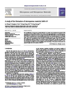
pair of ?xed supporting rings as they may be used accord ing to the invention; FIG. 4 shows in similar representation a different .form on construction of a pair of supporting rings; FIG. 5 shows in axial section the upper half of the preferred form of a pipe connection designed according to the invention, with two packing rings and three sup
porting rings; FIG. 6 shows in axial section the production of the preferred form of a sleeve end designed according to the
invention, with only one packing ring and two supporting rings during the insertion of the core; FIG. 7 shows the same construction after completed in
sertion of the core; form particularly favorable with regard to strength. It is further particularly advantageous for the method of in 25 FIG. 8 shows on a different scale, from the side, the
stallation according to the invention, which will be ex
preferred form of a core for the production of a sleeve
plained later. The ?xed ring consists advantageously of plastic.
with supporting rings in the circumferential furrow after completed ?tting of the pipe end onto the core;
FIG. 9 shows diagrammatically on a different scale Thermoplastic material is preferred. Best suited is a plastic of a softening temperature equal to or preferably some 30 the whole arrangement for carying out the method ac
what higher than that used for the piper, as this favors the
method of production explained later. The selection of material is advantageously made so that the materials of the ?xed rings and of the pipe have the same chemical and physical behavior.
The invention comprises also a method for the produc tion of a pipe sleeve of thermoplastic material with ?xed
cording to the invention, from the side; FIG. 10 shows the view from the left of FIG. 9; FIG. 11 shows the view from about of FIG. 9; and FIG. 12 shows on a different scale a ?lling ring. The pipe connection in FIGS. 1 and 2 between the ex
truded pipes 1 and 2 consisting of polyvinyl chloride has a sleeve 3 provided with an annular furrow 4. In the
latter extends the elastic packing ring 5, made of natural or synthetic rubber, which by its internal ridge 12 applies porting ring or rings and possibly also one or more pack 40 sealingly against the inserted pipe end 1. As can be seen from FIG. 2, the ring groove 6 formed ing rings, or ?lling rings which can be removed again by the annular furrow 4 has approximately the form of after formation of the sleeve, are placed on a substan
supporting rings in the ring groove.
This method is distinguished in that the continuous sup
a trapezoid which closely approaches the form of a rec tially cylindrical core whose outside diameter is equal to tangle. The edges of the ring groove are rounded out. the desired inside diameter of the sleeve, in that this core with the rings is inserted into the end of the pipe, widened 45 The depth of the ring groove is preferably one half of or to be widened to form the sleeve and heated to the
its axial extent.
Into the ring groove the packing ring 5 is placed. It range of thermoelastic deformability, in that the sleeve end is held there, even if at great pipe diameters its stiffness is consolidated over the core and over the rings by cool is not su?icient, by application against the lateral zones ing, in that the core is pulled out of the sleeve end, and in that ?nally the ?lling ring or rings, if any, are removed 50 7 and 8 of the ring groove, since its extent in axial direc tion in the relaxed state is slightly greater than the cor from the sleeve. The supporting rings are now ?rmly responding dimension of the ring groove. The outer seated in the annular furrow of the sleeve. A special circumferential surface of ring 5 is drawn in concavely, advantage of this method resides in that with it at the so that its pro?le is limited externally by a gentle arc same time the sleeve can be shaped to the pipe end. Due to the fact that the sleeve end, that is, the pipe end al 55 line 9 which terminates in the rounded corners 10. Also on the inside, the corners 11 of the ring are rounded. ready widened or preferably still to be widened to form At 12 the ring shows an arch, which projects inwardly the sleeve, has been heated to the range of thermoelastic beyond the innermost limit line of the tolerance ?eld 13 deformability, the pipe end rises beyond the rings during for the outside diameter of the pipe end to be inserted. insertion of the core and contracts again elastically behind them to the diameter of the core. According to the princi 60 On both sides of the annular ridge 12, the inner surface
ple of relativity in mechanics, of course, the sleeve end
of the ring extends slightly arched inwardly at 14.
If now the pipe end 1 is inserted, by its conically taper may alternatively be ?tted over the core without thereby ing end it pushes the annular ridge 12 outward, which going outside the invention. then applies sealingly against the pipe end. Further the In the case of large pipe diameters it is advantageous if the sleeve is compressed from the outside before its re 65 air chamber 15 is compressed between annular furrow and outer surface of the ring, so that a constant pressure consolidation. The clinging of the material to the core
and the supporting rings is thereby favored. The method is conducted particularly favorably if this compression is
can act on the entire outer ring groove surface.
brought about with the aid of the external air pressure by
down and thus enlarged the contact surface of the ring,
The lateral ridges 11 of the ring are thereby pushed
suction of air from the zone between the sleeve and core. 70 owing to which a lower pressure per area acts on the inserted pipe. To avoid too rapid a consolidation of the sleeve end
present in the thermoelastic temperature range upon in sertion of the core, the latter is advantageously heated
beforehand. A temperature of 50 deg. C. has proved suit
able for polyvinyl chloride pipes.
Below is explained the construction with ?xed support
ing rings for the packing ring. In the construction shown in FIG. 5, the end of pipe 75 21 is designed as insertable sleeve 22. At 23 the sleeve
27,736 presents an enlargement in which are seated the ?xed sup porting rings 24, 25 and 26 as well as the packing rings 27 and 28. The pipe is made of polyvinyl chloride, as are
For carrying out the method according to the inven
also the ?xed rings 24, 25 and 26. The packing rings 27
tion, with rod 51 shifted toward the left, so that the pins 44 are drawn into the interior of the core, the supporting ring 40 is ?rst slid onto core 36, then the
and 28 are made of soft rubber. The connection is suitable for lines under pressure, both those under internal and those under external pressure. As can be seen from the drawing, the ?xed supporting
elastic rubber backing ring 42 and then the supporting ring 41. Meanwhile the bushings 37 and 38 are in the position shown in FIG. 6, where they are retained. The two supporting rings 40 and 41 may alternatively be
made of a plastic softening at a higher temperature than 23 of the sleeve by reason of their oblique outer surfaces. 10 that of the pipe. Next, the rod 51 is moved to the right, so that ring 41 is prevented from being displaced. Ad The supporting rings 25 and 26 or respectively 24 and vantageously the supporting rings 40 and 41 as well as 26 each leave between them a ring groove 30, 31 of ap the packing ring 42 and the core 36 are treated externally proximately trapezoidal cross-section. The cross~section with a lubricant before they are applied. of these ring grooves widens outwardly. Owing to this, Next, the core is inserted into the sleeve end 52 which the packing rings 27 and 28 ?nd therein an excellent ac in the meantime has been brought into an elastically de commodation and it is avoided that upon insertion of formable state by softening. In so doing, this sleeve end the pointed end, they are pushed out of the grooves hold is widened, as can be seen from FIG. 6. When the outer ing them. It is clear that the inside diameters of the ?xed most edge 52 of the sleeve end has reached the position supporting rings 24, 25 and 26 are greater by a small shown in FIG. 6, it pushes bushing 38 before it counter amount taking into account the manufacturing tolerances to the pressure of a weak spring power. When bushing 38 than the outside diameter of the pipe 29 to be inserted. has reached the outer stop collar on bushing 37, it actuates To avoid notch effects, the edges of the rings 24, 25 and a limit switch (not shown) which after a certain delay 26 applying against the inner surface of the sleeve are moves the bushings 37 and 38 to the left. In this state, the rounded. For the supporting rings 32 and 33 shown in FIG. 4, 25 outermost left end 52 of the sleeve has already embraced the packing ring 42 and holds the latter clamped together a groove of dovetail pro?le is provided for each in the in radial direction. Also, the end 52 has come far enough sides facing each other. These rings are especially suited on the outer conical circumference of the supporting ring for being ?rmly connected with the rubber ring. For this 40 that it no longer tends to push this ring before it, but purpose they are placed in the mold intended for the production of the rubber ring. When the rubber packing 30 retains it in its position due to the inclination of the circumferential surface of ring 40. The two bushings 37 ring is then molded, the dovetail-shaped grooves ?ll up and 38 are now dispensable and are therefore brought out with rubber and a ?rm, positive connection results. of active position. This state of the two rings is illus The sleeve construction shown in FIGS. 6 and 7 repre trated in FIG. 7. An important point, of course, is that the sents the preferred form of a sleeve with only one pack right end face of this bushing still applies by a sufficiently ing ring. It differs from the construction according to large area against the left end face of the sleeve end when FIG. 5 essentially in that one instead of two packing the two bushings 37 and 38 are retracted into the inactive rings is provided. Accordingly the axial extent of the position shown in FIG. 7. Next the core slides farther into entire packing construction is much smaller than in the the elastic sleeve end, to a portion which is adjacent that construction according to FIG. 5. 40 rising over the annular ridge formed on the rings and An embodiment of the method according to the inven which is more constricted. It slides until the left end tion for the production of the sleeve connection will 52 of the sleeve end abuts on the right end of the bushing now be further explained with reference to FIGS. 6 37. If necessary, the produced furrow can be copied also and 7, where the core 36 is shown in section in the upper half. from the outside. As a rule, however, this is not necessary. Finally the sleeve is cooled and thereby consolidated. Core 36 consists mainly of a steel shell, whose external 45 form corresponds essentially to the internal form of the Next, after movement of rod 51 to the left and the draw pipe sleeve to be produced. Its right end tapers to facili in in the pins 44 brought about thereby, the core 36 can tate the sliding on (FIG. 7) of the thermoplastic pipe end. be pulled out of the ?nished sleeve. For holding the right-hand supporting ring 41, the core The next operation can begin. possesses some radially movable pins 44, which under 50 It is more advantageous and simple than with the ap
rings 25 apply ?rmly against the wall of the enlargement
the action of a spring 45 tend to move into the core far enough so as not to protrude beyond the circumferential surface of the core. These pins cooperate with a conical control piece 49 which is seated on the rod 51 which is
guided axially in the bearing disks 48 and 50. If the rod is displaced by axial displacement to the right into the position shown in FIGS. 6 and 7, the pins 44 are pushed outward radially and thus form stops for the supporting ring 41. The core 36 has further mounted on it for axial displacement a bushing 37 which serves to secure the sup
porting ring 40 against being seized by the end 52 of the sleeve end 47 an dbeing displaced along the core. As the end of the supporting ring 40 at left in FIGS. 6 and 7 advantageously has sharp edges, as far as this is possible,
paratus illustrated in FIGS. 6 and 7 to carry out the method with the apparatus shown in FIGS. 8 to 11. The apparatus carries on a base 60 a deforming core 61.
Above core 61 is a sprinkling nozzle 62 for cooling and consolidating the pipe sleeve 63 shaped on core 61. Core 61 contains a central bore 64 which is connected through a line 65 to an air suction device 66. From bore 64, thin bores 67, 68, 69 and 70 extend radially to the zones of the surface of the core at which by the production of a vacu urn a particularly good clinging of the deformable sleeve to the core is to be brought about. Core 61 possesses
in ring grooves 71 and 72 so-called O-rings 73 and 74, which upon production of a vacuum between core 61
65 and sleeve 63 seal the zone between them from the out side. At its left end the core has a stop 75 for the thermo between bushing 37 and supporting ring 40 is conical, as
to avoid the formation of dirt chambers, the contact area
plastic pipe sleeve 63. Also a low step 65 is provided at the core circumference, against which the supporting a second bushing 38, whose function it is to retain the 70 ring 77 braces itself when the pipe is ?tted onto the core. This step is very low. Its height is for example 1 mm. packing ring 42 before insertion thereof into the elasti In front of core 61, the base 60 carries, displaceable cally deformable sleeve end 47 radially inward. During in axial direction of the core by means of a hydraulic insertion into the sleeve end, the right end face of this cylinder 78, a collet 79 for clamping the pipe to be de ring is forced by the sleeve end 52 to slide on the bush ing 37. 75 formed. Collet 79 is opened and closed by means of a hy
indicated in the drawing. On bushing 37 is mounted, also for axial displacement,
7
27,736
draulic cylinder 80. Base 60 contains a hydraulic unit 81 for the actuation of the hydraulic cylinders 78 and 80. To produce a pipe sleeve with supporting rings 77 and
8 2. A method according to claim 1 wherein the sleeve
82, ?rst the core 61 is heated to about 50 deg. C. Then the
is formed from the outside. 3. A method according to claim 1 wherein the sleeve is formed by internal suction between the sleeve and
closed supporting ring 77, an elastic but hard ?lling ring
core.
83, which is slotted in the manner shown in FIG. 12, and the second supporting ring 82 are ?tted on the core in the
4. In a method for forming at the end of a pipe of thermoplastic material a widened sleeve having in an in ner circumferential groove at least one packing ring and at least one additional ring constituting an axial counter
position shown in FIG. 8. Then the pipe, having been made elastically deformable in the end zone by heating
to about 110 deg. (1., is clamped into the collet 79 so 10 bearing for the packing ring, the steps of placing at least one additional ring and at least one ?lling [rings] ring on a substantially cylindrical core whose outside diameter about the axis 84. Plate 85 is then pivoted out of the is equal to the desired inside diameter of the sleeve and path of movement of the pipe and the pipe is pushed by the heating the sleeve to the range of thermoelastic deforma hydraulic cylinder 78 over core 61 into the position shown bility, thereafter moving the core with the rings into said in FIG. 8. Then the vacuum unit 66 is switched on, which end of the pipe and allowing the part of said end of the by suction of air through lines 65, 64, 67, 69 and 70 causes pipe which has passed the rings to contract elastically, the still deformable pipe end 63 to apply closely to the said end of the pipe being formed into a sleeve having in core also at the points where the sleeve of the pipe is an inner groove [which constitutes the ?rst said groove] pinched inward. the [packing] ?lling and additional rings, thereafter con About 1/3 to 1/2 minute later, the sprinkling nozzle 62
that its end applies against the stop plate 85 pivotable
is switched on. This lets water run onto the ?nished
solidating the sleeve by cooling, thereafter extracting the
pipe sleeve and thereby cools and consolidates the latter.
core from the sleeve, the rings remaining in the groove,
and thereafter replacing [each] said ?lling ring with a Then, after switching off the vacuum unit 66 and the nor. packing ring. zle 62, the collet 79 with the pipe is taken away from the 5. A method according to claim 4 wherein the sleeve core 61. The pipe takes along parts 77, 83 and 82. Now the 25 is formed from the outside. pipe is taken out of the collet 79. By means of a mandrel 6. A method according to claim 4 wherein the sleeve introduced in bore 86, the ?lling ring 83 is pulled in is formed by internal suction between the sleeve and core. ward under elastic deformation and removed from the 7. A method according to claim 4 wherein two addi interior of the sleeve. Into the opened ring groove, a packing ring, preferably of the kind shown in FIG. 2, 30 tional rings and one ?lling ring are placed on the core. is now placed under elastic deformation. References Cited What is claimed is: 1. In a method for forming at the end of a pipe of thermoplastic material a widened sleeve having in an inner circumferential groove at least one packing ring and at least one additional ring constituting an axial coun
ter-bearing for the packing ring, the steps of placing said at least one additional ring and said packing ring on a
The following references, cited by the Examiner, are of record in the patented ?le of this patent or the original
patent.
UNITED STATES PATENTS 2,766,806 3,265,410
10/1956 8/1966
Rothermel _______ __ 264——92 X Lorang _________ __ 285—231 X
substantially cylindrical core whose outside diameter is equal to the desired inside diameter of the sleeve and heat 40 FOREIGN PATENTS ing the sleeve to the range of thermoelastic deformability, 852,578 10/1960 Great Britain ______ _- 264—-249 thereafter moving the core with the rings into said end 1,172,418 6/1964 Germany _________ __ 264—249 of the pipe, by relative movement between the core and pipe, and allowing the part of said end of the pipe which CHARLIE T. MOON, Primary Examiner has passed the rings to contract elastically, said end of the pipe being formed into said sleeve having in a resulting U.S. Cl. X.R. inner groove which constitutes the ?rst said groove the
packing and additional rings, thereafter consolidating the sleeve by cooling, and thereafter extracting the core from 50 the sleeve, the rings remaining in the groove.
29—450, 451; 264—92, 249; 277-—l, 190; 285-——23l