98
J. Opt. Soc. Am. A / Vol. 25, No. 1 / January 2008
Berg et al.
Reflection symmetry of a sphere’s internal field and its consequences on scattering: a microphysical approach Matthew J. Berg, Christopher M. Sorensen,* and Amitabha Chakrabarti Department of Physics, Kansas State University, Manhattan, Kansas, 66506-2601, USA *Corresponding author:
[email protected] Received July 30, 2007; accepted October 5, 2007; posted October 31, 2007 (Doc. ID 85835); published December 12, 2007 We examine the reflection symmetries of the electromagnetic wave inside of a uniform spherical particle and identify the consequences of the symmetries for the Stokes parameters describing the polarization state of the far-field scattered wave. The connection between the two waves is described from a microphysical perspective that illustrates the wavelet-superposition origin of the scattered wave. In contrast to more conventional approaches, this microphysical perspective yields new insight into the physical character of the scattering of a plane wave by a sphere. The results of simulations are presented, which graphically demonstrate the relation between the symmetries present in the internal wave and the polarization state of the scattered wave. © 2007 Optical Society of America OCIS codes: 290.4020, 290.5820, 290.5850, 260.5430, 120.2130, 120.5240.
1. INTRODUCTION This work identifies the reflection symmetries of the electromagnetic wave inside of a spherical particle and describes the connection between this internal wave and the wave scattered by the particle in the far-field zone. This connection has been known for some time and has recently been used to explain aspects of the particle’s backscattering behavior [1,2]. Previous interest in the wave inside of a spherical particle has been motivated mainly by secondary effects such as stimulated Raman and Brillouin scattering, lasing, and particle heating [3–12]. Here however, the internal wave is regarded as the source of the scattered wave, and the influences of the internal wave’s symmetries on the far-field measurable quantities derived from the scattered wave (that is, the Stokes parameters), are determined. An extensive foundation of work exists relating the symmetry of a single particle or of a multiparticle group to the structure of its scattered wave [13–23]. In contrast to the approaches taken in the previous work, here the connection between the the sphere’s internal and scattered waves is described from a microphysical wavesuperposition perspective. This microphysical approach treats the internal wave residing in the particle’s volume elements as sources that radiate their contributions to the observation point and hence build up the scattered wave. As a result, a physical interpretation of the effects of the sphere’s symmetry on the polarization state of the scattered wave emerges. This same physical understanding, however, is not achieved from the more conventional approaches of analyzing the character of the Mie series for the scattered wave or the matrix transformation between the incident and scattered waves. The article begins by defining the scattering arrangement and then derives the reflection symmetries of the 1084-7529/08/010098-10/$15.00
sphere’s internal field. Next the microphysical model is presented, and the consequences of the internal wave’s symmetry on the polarization state of the far-field scattered wave are described.
2. SCATTERING ARRANGEMENT Consider a uniform sphere of radius R and refractive index m located at the origin and surrounded by vacuum. A linearly polarized plane wave of wavelength is incident ˆ inc direcon the sphere traveling along the z-axis in the n tion. The wavenumber is k = 2 / , and the polarization is along the x-axis, see Fig. 1. The electric and magnetic fields of the incident wave at r are ˆ ·n ˆ inc兲xˆ , Einc共r兲 = Einc o exp共ikrr Binc共r兲 =
k
ˆ inc ⫻ Einc共r兲, n
共1兲
共2兲
respectively, where Einc is the real-valued wave amplio tude. All field quantities in this work share the same harmonic time dependence exp共−it兲, where = kc, and c = 共⑀oo兲−1/2 is the speed of light, with ⑀o and o being the permittivity and permeability of free space, respectively. For conciseness, this time dependence is suppressed. The scattering arrangement in this work is defined as the geometric configuration formed by the sphere, the polarization, and the propagation direction of the incident wave. The sphere’s surface, denoted by S, separates space into two volumes; the volume internal to the sphere’s surface denoted by Vint, and the volume external to it denoted by Vext. The sphere is surrounded by a large imaginary spherical surface Sl also centered on the origin. The observation point r is restricted to points on Sl, and it is © 2008 Optical Society of America
Berg et al.
Vol. 25, No. 1 / January 2008 / J. Opt. Soc. Am. A
99
Xn共r兲 = Rn共r兲sin cos + ⌰n共r兲cos cos − ⌽n共r兲sin , 共8兲 Yn共r兲 = Rn共r兲sin sin + ⌰n共r兲cos sin + ⌽n共r兲cos , 共9兲 Zn共r兲 = Rn共r兲cos − ⌰n共r兲sin .
共10兲
Equations (8)–(10) now give the internal field in Cartesian coordinates ⬁
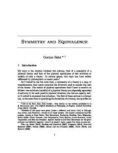
Eint共r兲 = Fig. 1. (Color online) Scattering arrangement. Shown at the tip of r is the scattered electric field Esca and the polarization ellipse discussed in Section 4.
assumed that the size of Sl is large enough that r satisfies the far-field conditions of [24].
3. REFLECTION SYMMETRY OF THE INTERNAL FIELD The Mie internal electric and magnetic fields can be cast into a form that readily demonstrates their reflection symmetry. The electric field inside of the sphere is [25] ⬁
Eint共r兲 =
兺 E 关c M 共r兲 − id N 共r兲兴, n
n
n
n
n
r 苸 Vint ,
共3兲
n=1
and the magnetic field follows as Bint共r兲 = −
1
ⵜ ⫻ Eint共r兲,
r 苸 Vint .
共4兲
The connection between Eint and Bint in Eq. (4) essentially allows one to consider only the electric field when analyzing the wave’s reflection symmetry, see [14]. In Eq. (3), En = inEinc o 共2n + 1兲 / n共n + 1兲 and the functions Mn and Nn are vector spherical wave functions. These functions are usually formulated in spherical polar coordinates, and explicit expressions for them are given in [25]. The expansion coefficients cn and dn in Eq. (3) are determined by the boundary conditions of the fields at S and depend only on the sphere’s size parameter kR, and refractive index m. Because of their independence on the location of the observation point, cn and dn are not explicitly given here. The internal electric field can be expressed in Cartesian coordinates by defining the radial, polar, and azimuthal functions Rn共r兲 = En关cnMn共r兲 − idnNn共r兲兴 · rˆ ,
共5兲
⌰n共r兲 = En关cnMn共r兲 − idnNn共r兲兴 · ˆ ,
共6兲
ˆ, ⌽n共r兲 = En关cnMn共r兲 − idnNn共r兲兴 ·
共7兲
respectively. Then the rectangular functions Xn, Yn, and Zn are defined as
兺 关X 共r兲xˆ + Y 共r兲yˆ + Z 共r兲zˆ 兴. n
n
n
共11兲
n=1
To describe the reflection symmetry of Eint and of the scattering arrangement, let ⌸x, ⌸y, and ⌸z denote the y − z, x − z, and x − y planes through the origin, respectively. The intersection of the large spherical surface Sl with the ⌸x and ⌸y planes defines the horizontal contour Ch and the vertical contour Cv, respectively. Note that these contours can have practical significance; in some simple scattering measurements the detector is confined to one of these contours [26]. Figure 2 shows this configuration of planes and contours, and inspection of Fig. 2 demonstrates that the scattering arrangement is invariant under reflection about the ⌸x and ⌸y planes, [recall from Eqs. (1) and (2) that the direction of the incident field oscillates]. It is not, however, invariant under reflection about the ⌸z plane because of the propagation direction ˆ inc兲 of the incident wave. 共n Expressing r in Cartesian coordinates reveals the reflection symmetry of Eint by the behavior of the rectangular functions Xn, Yn, and Zn under the transformations x → −x and y → −y. Upon making these transformations in Eqs. (8)–(10), one eventually finds that Xn共x,y,z兲 = Xn共− x,y,z兲 = Xn共x,− y,z兲,
共12兲
Yn共x,y,z兲 = − Yn共− x,y,z兲 = − Yn共x,− y,z兲,
共13兲
Fig. 2. (Color online) Sketch showing the ⌸x, ⌸y, and ⌸z planes and Ch and Cv contours. The planes pass through the origin of the coordinate system and the center of the sphere.
100
J. Opt. Soc. Am. A / Vol. 25, No. 1 / January 2008
Zn共x,y,z兲 = − Zn共− x,y,z兲 = Zn共x,− y,z兲.
Berg et al.
共14兲
Because the components of the internal field must be continuous throughout Vint since no sources reside in the particle, Eqs. (13) and (14) provide the additional conditions that Yn共r兲 = 0,
for x = 0 or y = 0,
共15兲
Zn共r兲 = 0,
for x = 0.
共16兲
Equation (12) shows that the x-component of the internal field is invariant under reflection about the ⌸x and ⌸y planes, whereas Eq. (13) shows that the y-component of the field switches sign upon reflection about these planes. Equation (14) demonstrates that the z-component of the field is invariant about the ⌸y plane but switches sign about the ⌸x plane. From Eqs. (15) and (16) one can see that the y-component of the internal field vanishes for points on the ⌸x and ⌸y, planes, and the z-component vanishes for points on the ⌸x plane. This means that the internal field can have only an x-component in the ⌸x plane. Moreover, because of Eq. (12), the field magnitude must have reflection symmetry about the z-axis in this plane. A numerical implementation of the Mie solution (verified by comparison to the BHMIE program of [25]) is used to graphically demonstrate these symmetries. Figure 3 shows the normalized field magnitude in the ⌸x plane for a sphere with kR = 12 and m = 1.33+ 0i. Figures 4 and 5 show the field inside this same sphere except in the ⌸y and ⌸z planes. The color code for these plots is given in Fig. 3 and is in log scale. The colors are assigned relative to Fig. 3, which enables comparison between the plots.
Fig. 4.
Esca共r兲 =
4
r
冕
共m2 − 1兲共IJ − rˆ 丢 rˆ 兲
Eint共r⬘兲exp共− ikr⬘ · rˆ 兲dr⬘ ,
共17兲
Vint
where JI is the Cartesian identity dyad and rˆ 丢 rˆ is the dyad formed by the direct product of rˆ with itself in the Cartesian basis [24,27]. In the far-field zone, the scattered wave is a transverse spherical wave [24]. The scattered magnetic field is then given by Bsca共r兲 =
sca
Fig. 3. (Color online) Electric field inside and surrounding a sphere with kR = 12 and m = 1.33+ 0i for points in the ⌸x plane, recall Fig. 2. The sphere’s surface is outlined. The normalized field magnitude is shown by the color shades in log scale. Contour lines are also shown to give relief to the plot when not viewed in color. No field vectors are shown since the field is normal to this plane, see Eqs. (15) and (16).
exp共ikr兲 k2
·
4. MICROPHYSICAL APPROACH It has been shown that the scattered electric field E at observation points in the far-field zone is related to Eint via the volume integral equation (VIE) as
(Color online) Same as Fig. 3 except for the ⌸y plane.
k
rˆ ⫻ Esca共r兲.
共18兲
Because of the transverse nature of the scattered wave, both Esca and Bsca are tangent to the large spherical surface Sl. The scattered electric field is then fully described ˆ unit vectors at r. In by its projections along the ˆ and general, the polarization state of the sphere’s scattered
Fig. 5. plane.
(Color online) Same as Figs. 3 and 4 except for the ⌸z
Berg et al.
wave at r is elliptical, meaning that the tip of the Esca vector will trace out an ellipse (the polarization ellipse) in time at r, see Fig. 1 [28,29]. The polarization ellipse describes the wave’s polarization state and is characterized by three quantities; its ellipticity, defined as the ratio of ˆ its minor and major axes, its orientation in the ˆ − sca plane, and the sense of rotation of E in time [1]. Consider dividing the sphere into many infinitesimally small volume elements ⌬V each located by ri. The size of a volume element is taken to be sufficiently small enough that the electric field throughout it is uniform. Then by Eq. (17) exp共ikr兲 k
Esca共r兲 =
2
4
r
共m2 − 1兲 lim
⌬V→0
兺 共IJ − rˆ 丢 rˆ 兲 i
· E 共ri兲exp共− ikri · rˆ 兲⌬V,
共19兲
int
where the sum runs over the locations ri of every volume element in the sphere. Next, let co = k2共m2 − 1兲⌬V / 共4兲 and define zi共rˆ 兲 =
co兵关Eint x 共ri兲cos
+
Eint y 共ri兲sin
兴cos
− Ezint共ri兲sin 其exp共− ikri · rˆ 兲,
共20兲
int ˆ 兲, zi共rˆ 兲 = co关Eint y 共ri兲cos − Ex 共ri兲sin 兴exp共− ikri · r
共21兲 int int where Eint x , Ey , and Ez are the Cartesian components of the internal field. The quantities zi and zi of Eqs. (20) and (21) have physical significance (discussed next) and give the following form for the scattered field
exp共ikr兲 r
兺 关z 共rˆ 兲ˆ + z 共rˆ 兲ˆ 兴, i
i
101
ˆ 兲, zi共rˆ 兲 = ⫿ coEint x 共ri兲exp共− ikri · r
共24兲
where the top and bottom signs in Eq. (23) correspond to = / 2 and = 3 / 2, respectively. Next, the sum over the sphere’s volume in Eq. (22) for the -component of the field is split in two. One sum covers the hemisphere for internal points with x 艌 0, and the other sum covers the hemisphere with x ⬍ 0, that is,
兺 z 共rˆ 兲 = 兺 i
i
x艌
zj共rˆ 兲 +
j
兺
x⬍
zk共rˆ 兲,
共25兲
k
where the points rj and rk [recall Eqs. (23) and (24)] are mirror points about the ⌸x plane, see Fig. 6. From Eqs. (13) and (14) one sees that the y- and z-components of the internal field appearing in Eq. (23) change sign upon reflection about the ⌸x plane. This means that the sums over the x 艌 0 and x ⬍ 0 hemispheres in Eq. (25) cancel each other term-by-term, that is, zj共rˆ 兲 = − zk共rˆ 兲.
共26兲
Then from Eqs. (22) and (24),
and
Esca共r兲 =
Vol. 25, No. 1 / January 2008 / J. Opt. Soc. Am. A
Esca共Rlrˆ 兲 = ⫿ co
exp共ikRl兲 Rl
兺E
int x 共ri兲exp共−
ˆ, ikri · rˆ 兲
i
r 苸 Ch ,
共27兲
where the top and bottom signs correspond to = / 2 and = 3 / 2, respectively.
共22兲
i
where the limit ⌬V → 0 appearing in Eq. (19) is assumed. Equation (22) reveals the meaning of the far-field form of the VIE formulation of the scattered field [24]. The internal electric field within a volume element acts as the source of an outward-traveling transverse spherical wave (or wavelet for short). The amplitudes of the components of the electric field of the ith wavelet are given by the complex-valued quantities zi and zi, which depend on the location of the the volume element ri and the direction to the observation point rˆ . The scattered field is then the superposition of all the wavelet fields radiated out to r, that is Eq. (22). This wavelet-based description of the scattered field forms the basis for a microphysical perspective of the scattering process.
5. CONSEQUENCES OF THE SYMMETRY Consider placing the observation point somewhere on the Ch contour. With r on this contour, the azimuthal angle can have two values, = / 2 and = 3 / 2, and one finds from Eq. (20) that ˆ 兲, zi共rˆ 兲 = − co关Ezint共ri兲sin ⫿ Eint y 共ri兲cos 兴exp共− ikri · r 共23兲 and from Eq. (21) that
Fig. 6. Sketch of the hemispheres used to derive Eqs. (27) and (32). The sphere is separated to delineate the hemispheres. The internal locations rj and rk are mirror points about the ⌸x plane (top sketch) and the ⌸y plane (bottom sketch).
102
J. Opt. Soc. Am. A / Vol. 25, No. 1 / January 2008
Berg et al.
Equation (27) shows that, for observation points on the Ch contour, the scattered wave is determined solely by the x-component of the sphere’s internal electric field. The symmetry of the internal field leads to the cancellation of the -components of the wavelet amplitudes, which carry the dependence on the other Cartesian components of the internal field. Moreover, the direction of the scattered field for observation points on this contour is only along ˆ direction, (which is parallel or antiparallel to the xˆ the direction on Ch) demonstrating that the scattered wave for points on Ch has the same (linear) polarization state as the incident wave. Next consider placing the observation point on the Cv contour. Here = 0 and = . Now Eqs. (20) and (21) become ˆ 兲, zi共rˆ 兲 = − co关Ezint共ri兲sin ⫿ Eint x 共ri兲cos 兴exp共− ikri · r 共28兲 and ˆ 兲, zi共rˆ 兲 = ± coEint y 共ri兲exp共− ikri · r
共29兲
where the top and bottom signs in Eqs. (28) and (29) correspond to = 0 and = , respectively. The sum in Eq. (22) is again split in two like above except here the hemispheres correspond to y 艌 0 and y ⬍ 0, see Fig. 6. Then, for the -component,
兺 z 共rˆ 兲 = 兺 i
i
y艌
zj共rˆ 兲 +
j
兺
y⬍
zk共rˆ 兲,
共30兲
k
where rj and rk are now mirror points about the ⌸y plane. From the behavior of the y-component of Eint given in Eq. (13) combined with Eq. (29), one finds that zj共rˆ 兲 = − zk共rˆ 兲,
共31兲
plicitly build the symmetries of the sphere’s internal field into these parameters, the double sums which cover the entire sphere volume are separated into component sums of the volume elements contained in the four regions of the sphere’s interior bounded by the intersection of the ⌸x and ⌸y planes and the sphere’s surface S. These wedgeshaped regions, or quadrants for short, are labeled by the Roman numerals I–IV, and the volume of each quadrant is denoted VI – VIV. Using the symmetry properties of Eqs. (12)–(14), the double sums over the sphere’s four quadrants are reduced to a single double sum over only the first quadrant, VI. To explain how this is done, consider two arbitrary volume element locations rj共I兲 and rk共I兲 in VI. Let rj共II兲 , rj共III兲 , rj共IV兲, and rk共II兲 , rk共III兲 , rk共IV兲 be the locations obtained in the remaining three quadrants by performing successive reflections of rj and rk about the ⌸x and ⌸y planes. Figure 7 shows these locations in their respective quadrants. Next, 共I兲 共I兲 共I兲 let zj共I兲 , zj , zk , zk be the wavelet amplitudes of Eqs. (20) and (21) evaluated for the points rj共I兲 and rk共I兲, respectively. 共II兲 共IV兲 共IV兲 Finally let zj共II兲 be the wavelet ampli , z j , . . . z j , z j tudes zj and zj evaluated for the reflected points rj共II兲 , rj共III兲 , rj共IV兲, and similarly for the k subscript terms. Because the points in the VII – VIV quadrants are related to the points in the VI quadrant through the same reflection operations that define the reflection symmetry of the internal field, the wavelet amplitudes in the VII – VIV quadrants are directly related to the amplitudes in only the VI quadrant. With these considerations, the Stokes parameters can be expressed as Eqs. (33)–(36) below as double sums over only the VI quadrant, I共rˆ 兲 =
Esca共Rlrˆ 兲 = − co
Rl
兺
Q共rˆ 兲 = 关Ezint共ri兲sin
⫿
Eint x 共ri兲cos
2
冑
⑀o o
兵z ␣ 共rˆ 兲关z  共rˆ 兲兴 兺 兺 ␣ 共 兲 j
共I兲
j,k
共 兲 k
*
+ zj共␣兲共rˆ 兲关zk共兲共rˆ 兲兴*其,
,
共33兲
which, from Eqs. (22) and (29), demonstrates that there is no contribution to the scattered field on Cv from the y-component of the internal electric field. Then, exp共ikRl兲
1
兴
1 2
冑
⑀o o
兵z ␣ 共rˆ 兲关z  共rˆ 兲兴 兺 兺 ␣ 共 兲 j
共I兲
j,k
共 兲 k
*
− zj共␣兲共rˆ 兲关zk共兲共rˆ 兲兴*其,
,
共34兲
i
⫻exp共− ikri · rˆ 兲ˆ ,
r 苸 Cv ,
共32兲
where again the top and bottom signs correspond to = 0 and = , respectively. This result demonstrates that the scattered electric field for points on Cv has only a -component and hence is linearly polarized. Using the Stokes parameter formalism, the polarization state of the far-field scattered wave is expressed below in terms of the wavelet amplitudes of Eqs. (20) and (21). The Stokes parameters consist of four quantities I, Q, U, and V that have units of power and can be directly measured. Explicit expressions for the parameters and a description of their measurement can be found in [27]. The quantity I describes the intensity of the scattered wave and the overall size of the polarization ellipse, whereas Q and U collectively describe its orientation and ellipticity, and V describes its sense of rotation. In casting the Stokes parameters in terms of the wavelet amplitudes of Eqs. (20) and (21), one obtains a double sum over the sphere’s volume for each parameter. To ex-
U共rˆ 兲 = −
1 2
冑
⑀o o
兵z ␣ 共rˆ 兲关z  共rˆ 兲兴 兺 兺 ␣ 共 兲 j
共I兲
j,k
共 兲 k
*
+ zj共␣兲共rˆ 兲关zk共兲共rˆ 兲兴*其,
,
共35兲
V共rˆ 兲 =
i 2
冑
⑀o o
兵z ␣ 共rˆ 兲关z  共rˆ 兲兴 兺 兺 ␣ 共 兲 j
共I兲
j,k
共 兲 k
*
− zj共␣兲共rˆ 兲关zk共兲共rˆ 兲兴*其,
,
共36兲 where ␣ ,  苸 兵I , II, III, IV其, and the notation 兺共I兲 means that the sum covers the first quadrant VI only. The appendix provides the explicit expression for zj共␣兲 and zj共␣兲 that are needed to arrive at the symmetry properties in Eqs. (37)–(42) next. By making the transformations → − and → 2 − in Eqs. (33)–(36), (which describe the reflection of the observation point about the ⌸x and ⌸y planes, respectively) one finds that
Berg et al.
Vol. 25, No. 1 / January 2008 / J. Opt. Soc. Am. A
103
consistent with the Rayleigh limit. Referring to [28] shows that this result can, of course, also be deduced from the Mie series for the scattered electric field.
6. DEMONSTRATION OF THE AFFECT OF THE SYMMETRY ON THE POLARIZATION STATE
Fig. 7. Sketch of the internal points and quadrants of the sphere used to derive Eqs. (33)–(36). The incident wave travels through the page toward the reader, and the sketch shows the ⌸z slice through the sphere depicted in Fig. 2. The locations rj共II兲 , rj共III兲 , rj共IV兲 and rk共II兲 , rk共III兲 , rk共IV兲 are generated from the locations rj共I兲 and rk共I兲 in VI through successive reflections about the ⌸x and ⌸y planes.
I共, 兲 = I共, − 兲 = I共,2 − 兲,
共37兲
Q共, 兲 = Q共, − 兲 = Q共,2 − 兲,
共38兲
U共, 兲 = − U共, − 兲 = − U共,2 − 兲,
共39兲
V共, 兲 = − V共, − 兲 = − V共,2 − 兲.
共40兲
The symmetry conditions of Eqs. (37)–(40) result from the term-by-term equality of Eqs. (33)–(36) under the reflection transformations, which is a direct consequence of the internal field’s symmetry about these same planes. Equations (39) and (40) and the continuity of the Stokes parameters with direction provide the extra conditions U共,0兲 = U共, /2兲 = U共, 兲 = U共,3/2兲 = 0,
共41兲
V共,0兲 = V共, /2兲 = V共, 兲 = V共,3/2兲 = 0.
共42兲
The polarization state of the scattered wave for a sphere with kR = 4 and m = 1.25+ 0i is examined in detail next to graphically demonstrate the symmetries presented above. The size and refractive index of the sphere is chosen such that the structures in the scattered wave are not too complicated to examine graphically. Other kR and m values have been investigated by the authors and give the same qualitative results as described below. Figure 8 shows the polarization state of the scattered wave on the large imaginary spherical surface Sl where the ellipticity is indicated by gray shades. Lighter shades correspond to more linear polarization, whereas darker shades correspond to more circular polarization. The polarization ellipses are also shown for various points on Sl. The left-handed rotation of an ellipse is indicated by a thick red line, and the right-handed rotation is indicated by a thin blue line. The sense of rotation is right-handed if the scattered electric field vector rotates in the counterclockwise direction to an observer looking into the oncoming wave. Inspection of this figure shows that the wave is linearly polarized along the Ch and Cv contours as predicted by Eqs. (27) and (32). Figures 9–11 display the intensity, ellipticity and rotation of the scattered wave on Sl for the same sphere as in Fig. 8, except here the plots show all directions. The intersection of the ⌸x and ⌸y planes with Sl are indicated on
It is important to stress that these symmetries of the Stokes parameters, require all the reflection symmetries of the spheres internal field. Equations (37)–(42) are also obtained by [14,20,23]; however via different methods, there the analysis concerns either the scattered field’s structure only or the elements of a matrix transformation of the incident wave into the scattered wave. Neither demonstrates the effect of the internal wave’s structure. Notice that if the internal electric field is uniform and directed along the x-axis (contrary to earlier, more general considerations), then from Eqs. (20), (21), and (36) one can find that V共rˆ 兲 = 0,
ˆ, for Eint共r兲 = Eint x x
共43兲
where Eint x is a constant. A situation that would produce such a uniform internal field would be the so-called Rayleigh limit [25]. Equation (43) demonstrates that the scattered wave is linearly polarized in all directions, which is
Fig. 8. (Color online) The polarization state of the scattered wave for a sphere with kR = 4 and m = 1.25+ 0i. The plot shows the vibration ellipses at various points on Sl, recall Fig. 1. The bold red ellipses correspond to left-handed rotation of the field, whereas thin blue ellipses correspond to right-handed rotation. The ellipticity is shown in gray shades on Sl. Darker (lighter) shades indicate more elliptical (linear) polarization.
104
J. Opt. Soc. Am. A / Vol. 25, No. 1 / January 2008
Fig. 9. Intensity of the scattered wave on Sl. The intensity is normalized to the forward direction 共 = 0兲, and gray shades are assigned in log scale as indicated. The sphere is the same as in Fig. 8.
the plots by dashed lines. The intensity, Fig. 9, shows reflection symmetry about both the ⌸x and ⌸y planes. Notice from Fig. 10 that the scattered wave is, in general, elliptically polarized in all directions except those contained in the ⌸x and ⌸y planes. The ellipticity displays reflection symmetry about the ⌸x and ⌸y planes and shows that the wave is, overall, more linearly polarized in the forward directions as compared to the backward directions. The plot of the wave’s rotation in Fig. 11 reveals that the wave changes its sense of rotation upon reflection of the observation point about either of these planes. The angular distribution of the wave’s rotation appears to be “conserved”
Fig. 10. (Color online) Ellipticity of the scattered wave on Sl. The gray scale is the same as in Fig. 8, and the sphere is the same as in Figs. 8 and 9. The dashed lines show the intersection of the ⌸x and ⌸y planes with Sl. These lines also indicate the location of four of the seven L-lines, that separate the the angular regions of opposing rotation in Fig. 11. One of the four points of circular polarization, or C-points, is indicated by the gray (red online) dot in the upper left of the plot. See the text for a discussion of L-lines and C-points.
Berg et al.
Fig. 11. Rotation of the scattered wave on Sl. Black indicates left-handed rotation and white indicates right-handed rotation. The sphere is the same as in Figs. 8–10. Notice the correlation of the angular structure with that of Fig. 10.
in the sense that for each angular region of right-handed rotation, there is another region that is the mirror image to that region about the ⌸x or ⌸y planes that shows lefthanded rotation. Every reflection symmetry of Figs. 8–11 is explained by the results in Section 5. The figures show that the scattered wave is linearly polarized along the Ch and Cv contours. This can be understood from Eq. (42), which shows that V = 0 for directions lying in the ⌸x and ⌸y planes. Moreover, the orientation of the (linear) polarization is ˆ directions since U = 0 from Eq. (41) along either the ˆ or (see the ellipsometric interpretation given in [1]). Figure 9 shows that the intensity of the wave is invariant upon reflection about the ⌸x and ⌸y planes, which is due to the invariance of Eq. (37) upon reflection. The change in the wave’s rotation and the orientation of its polarization ellipse for directions reflected about the ⌸x and ⌸y planes is accounted for by the negative sign appearing in Eqs. (39) and (40). A comparison of the rotation of the scattered wave shown in Fig. 11 to the ellipticity shown in Fig. 10 reveals that the wave becomes linearly polarized where angular regions of opposing rotation meet. In this sense the angular structure of the ellipticity and the rotation of the wave are correlated. There are also distinct points where the ellipticity of the wave becomes circular, one of which is indicated Fig. 10. The points of circular polarization and the lines of linear polarization appear to be examples of the so-called “C-points,” and “L-lines,” respectively, of [30,31]. One can find seven such L-lines in Fig. 11 and four such C-points in Fig. 10.
7. INTERPRETATION By appealing to the microphysical perspective of scattering afforded by the VIE formalism, the analysis above connects the reflection symmetries of a sphere’s internal field to the overall structure of the polarization state of its scattered wave. This connection can be given a clearer physical meaning by remembering that the quantities zi
Berg et al.
Fig. 12. (Color online) This diagram illustrates the waveletcomponent cancellation that is responsible for the linear polarization state of the scattered wave on the Ch contour. A similar picture applies for the Cv contour. Internal mirror points rj and rk about the ⌸x plane are shown along with an example of the internal electric field vectors Eint共rj兲 and Eint共rk兲 that satisfy the symmetry conditions of Eqs. (12)–(16). Each of these internal wavelets contribute Ej and Ek to the scattered field, where the cancellation of their -components is evident.
and zi represent the amplitudes of the - and -components of each wavelet’s contribution to the farfield scattered wave. These amplitudes depend both on the field at a location inside the sphere and on the direction to the observation point. In this sense, the wavelet amplitudes facilitate the connection between the internal and scattered waves. For example, suppose that the observation point lies on the Ch contour. The sketch in Fig. 12 shows two wavelets located at points rj and rk inside a sphere. These points are mirror points about the ⌸x plane, and the electric fields shown at the points, Eint共rj兲 and Eint共rk兲, obey the symmetry properties of Eqs. (12)–(16). Shown at r are the contributions to the scattered field from these wavelets, Ej and Ek, respectively. The projections of Ej and Ek onto the ˆ direction are also shown. These projections are given by the wavelet amplitudes zj and zk, except for a factor of exp共ikr兲 / r, which is a constant on Ch, recall Eq. (22). Figure 12 demonstrates that these components of the wavelet’s contribution to the scattered field cancel each other, and hence it is only the -components that contribute. The contributing components in turn depend only on the x-component of the internal electric field and yield a linearly polarized scattered wave on the Ch contour. A similar cancellation process can be used to explain the linear polarization state of the scattered wave for observation points on the Cv contour. From this cancellation-based viewpoint, one can now understand that the ellipticity of the polarization state is due to the break in symmetry of the scattering arrangement that results from taking the observation point off the Ch or Cv contours. This break in symmetry prevents the unique cancellation of components that results in the linear polarization state and introduces a relative phase shift between the components.
8. COMMENTS None of the general results of this work rely on specific values for kR or m. Consequently, the symmetries of the internal field and the Stokes parameters are valid for a
Vol. 25, No. 1 / January 2008 / J. Opt. Soc. Am. A
105
sphere of any arbitrary size and refractive index provided that the illumination configuration of Fig. 1 is used. Note that when a sphere is illuminated by a linearly polarized incident wave, as in this work, the scattered wave is completely polarized in all directions [28]. There is no depolarization. That does not mean, however, that the polarization state does not change, and indeed this work reminds one that it does change, from linear to elliptical, with angle. One could, of course, derive the symmetry properties of the Stokes parameters in Eqs. (37)–(42) using the Mie scattered wave directly, see for example [20,23,28]. This wave is similar to the Mie internal wave in that it also involves an expansion of the wave in vector spherical wave functions except with different expansion coefficients. Each term in the expansion can be regarded as a partial wave that consists of an electric and magnetic part. These partial waves essentially provide a way to describe the structure of the scattered wave in terms of component waves of simpler form. For example, the scattered wave for a small sphere 共kR Ⰶ 1兲 with a moderate realvalued refractive index, will have an expansion that is dominated by the first electric partial wave [28]. This partial wave is equivalent in form to the far-field wave radiated by an oscillating electric dipole. For a more arbitrary sphere, higher-order partial waves will in general be present in the expansion. Although the partial waves are useful to describe the structure of the scattered wave, they offer no explanation for the physical origin of the structure; that information is encoded in a complicated way in the expansion coefficients via the boundary conditions on the surface of the particle. In using the partial waves to derive Eqs. (37)–(40), one is only able to show that the symmetry of the Stokes parameters is due to the mathematical behavior of the partial waves under reflection of rˆ about the ⌸x or ⌸y planes. Although this is a valid mathematical account of the symmetry and has utility in its own right, it does little to provide the wavesuperposition insight that the above microphysical approach yields.
9. CONCLUSION The electric field inside of a uniform dielectric sphere is shown to have reflection symmetries, and these symmetries’ consequences on the polarization state of the scattered wave are described. By regarding the internal wave as the source of the scattered wave, a microphysical, wavelet-superposition description of the scattering process is developed. The microphysical description is used to show that the scattered wave is linearly polarized in directions contained in the planes of reflection symmetry, and in general, is elliptically polarized in other directions. It is seen that some components of the internal electric field have no direct influence on the scattered wave for certain high symmetry directions. The angular structure of the rotation and ellipticity of the scattered wave’s polarization state are shown to be correlated. All the symmetry properties of the polarization state of the scattered wave found in this work have also been found by others. The analysis here, however, demonstrates that these properties are caused by the symmetric structure of the
106
J. Opt. Soc. Am. A / Vol. 25, No. 1 / January 2008
Berg et al.
internal wave, which in turn is caused by the spherical particle shape. Moreover, the symmetries are shown to cause cancellation of the wavelet components, which build up the scattered wave and hence demonstrate how the sphere’s symmetries are ultimately imprinted on the structure of the scattered wave.
APPENDIX A Here the explicit forms for the wavelet amplitudes zj共␣兲 and zj共␣兲 of Eqs. (33)–(42) required to prove the symmetry properties of the Stokes parameters in Eqs. (37)–(40) are given: zj共I兲共rˆ 兲 = co关Ex共rj兲cos cos + Ey共rj兲cos sin − Ez共rj兲sin 兴 ⫻ exp关− ik共rjx sin cos + rjy sin sin + rjz cos 兲兴,
共44兲
ACKNOWLEDGMENTS M. J. Berg is thankful for the helpful suggestions of Michael Mishchenko of the NASA Goddard Institute of Space Studies, O. Larry Weaver of Kansas State University, and Thomas Wriedt of the Institut fuer Werkstofftechnik at the Universität Bremen. This work was supported by the NASA Graduate Student Researchers Program.
REFERENCES 1.
2.
3.
zj共II兲共rˆ 兲 = co关Ex共rj兲cos cos − Ey共rj兲cos sin − Ez共rj兲sin 兴 ⫻ exp关− ik共rjx sin cos − rjy sin sin + rjz cos 兲兴,
4.
共45兲 5.
zj共III兲共rˆ 兲 = co关Ex共rj兲cos cos + Ey共rj兲cos sin 6.
+ Ez共rj兲sin 兴 ⫻ exp关− ik共− rjx sin cos − rjy sin sin + rjz cos 兲兴,
共46兲 7.
zj共IV兲共rˆ 兲 = co关Ex共rj兲cos cos − Ey共rj兲cos sin 8.
+ Ez共rj兲sin 兴 ⫻ exp关− ik共− rjx sin cos + rjy sin sin + rjz cos 兲兴,
共47兲
and zj共I兲共rˆ 兲
9. 10.
= co关Ey共rj兲cos − Ex共rj兲sin 兴exp关− ik共rjx sin cos + rjy sin sin + rjz cos 兲兴,
共48兲
zj共II兲共rˆ 兲 = co关− Ey共rj兲cos − Ex共rj兲sin 兴
12. 13.
⫻ exp关− ik共rjx sin cos − rjy sin sin + rjz cos 兲兴,
11.
14.
共49兲 15.
zj共III兲共rˆ 兲 = co关Ey共rj兲cos − Ex共rj兲sin 兴 ⫻ exp关− ik共− rjx sin cos − rjy sin sin + rjz cos 兲兴,
共50兲
zj共IV兲共rˆ 兲 = co关− Ey共rj兲cos − Ex共rj兲sin 兴
17.
⫻ exp关− ik共− rjx sin cos + rjy sin sin + rjz cos 兲兴,
16.
18.
共51兲
where co = k2共m2 − 1兲⌬V / 共4兲, and rj = rjxxˆ + rjyyˆ + rjzzˆ . These expressions are identical for the k subscript terms.
19.
M. I. Mishchenko, L. D. Travis, and A. A. Lacis, Scattering, Absorption, and Emission of Light by Small Particles (Cambridge U. Press, 2002), freely available in the pdf format at http://www.giss.nasa.gov/~crmim/books.html. J. Tyynelä, E. Zubko, G. Videen, and K. Muinonen, “Interrelating angular scattering characteristics to internal electric fields for wavelength-sized spherical particles,” J. Quant. Spectrosc. Radiat. Transf. 106, 520–534 (2007). C. Li, G. W. Kattawar, and P. W. Zhai, “Electric and mangnetic energy density distributions inside and outside dielectric particles illuminated by a plane electromagnetic wave,” Opt. Express 13, 4554–4559 (2005). N. Velesco, T. Kaiser, and G. Schweiger, “Computation of the internal field of a large spherical particle by use of the geometrical-optics approximation,” Appl. Opt. 36, 8724–8728 (1997). L. Kai and A. D’Alessio, “Internal-field characteristics of spherical particles,” Part. Part. Syst. Charact. 12, 237–241 (1995). E. E. M. Khaled, S. C. Hill, and P. W. Barber, “Internal electric energy in a spherical particle illuminated with a plane wave or off-axis Gaussian beam,” Appl. Opt. 33, 524–532 (1994). G. Chen, D. Q. Chowdhury, and R. K. Chang, “Laserinduced radiation leakage from microdroplets,” J. Opt. Soc. Am. B 10, 620–632 (1993). H. M. Lai, P. T. Leung, K. L. Poon, and K. Young, “Characterization of the internal energy density in Mie scattering,” J. Opt. Soc. Am. A 8, 1553–1558 (1991). C. C. Dobson and J. W. Lewis, “Survey of the Mie problem source function,” J. Opt. Soc. Am. A 6, 463–466 (1989). P. Chýlek, J. D. Pendleton, and R. G. Pinnick, “Internal and near-surface scattered fields of a spherical particle at resonant conditions,” Appl. Opt. 24, 3940–3942 (1985). P. W. Barber and S. C. Hill, Light Scattering by Particles: Computational Methods (World Scientific, 1990). P. W. Dusel, M. Kerker, and D. D. Cooke, “Distribution of absorption centers within irradiated spheres,” J. Opt. Soc. Am. 69, 55–59 (1979). C. E. Baum and N. H. Kritikos, Electromagnetic Symmetry (Taylor & Francis, 1995). S. H. Yueh, R. Kwok, and S. V. Nghiem, “Polarimetric scattering and emission properties of targets with reflection symmetry,” Radio Sci. 29, 1409–1420 (1994). C. H. Hu, G. W. Kattawar, M. E. Parkin, and P. Herb, “Symmetry theorems on the forward and backward scattering Mueller matrices for light scattering from a nonspherical dielectric scatterer,” Appl. Opt. 26, 4159–4173 (1987). K. F. Ren, G. Gréhan, and G. Gouesbet, “Symmetry relations in generalized Lorentz–Mie theory,” J. Opt. Soc. Am. A 11, 1812–1817 (1994). F. M. Schultz, K. Stamnes, and J. J. Stamnes, “Point-group symmetries in electromagnetic scattering,” J. Opt. Soc. Am. A 16, 853–865 (1999). J. W. Hovenier, “Symmetry relations for forward and backward scattering by randomly oriented particles,” J. Quant. Spectrosc. Radiat. Transf. 60, 483–492 (1998). S. V. Nghiem, S. H. Yueh, R. Kwok, and F. K. Li, “Symmetry properties in polarimetric remote sensing,” Radio Sci. 27, 693–711 (1992).
Berg et al. 20. 21. 22. 23. 24. 25.
J. W. Hovenier, “Principles of symmetry for polarization studies of planets,” Astron. Astrophys. 7, 86–90 (1970). J. W. Hovenier, “Symmetry relationships for scattering of polarized light in a slab of randomly oriented particles,” J. Atmos. Sci. 26, 488–489 (1969). P. C. Waterman, “Symmetry, unitarity, and geometry in electromagnetic symmetry,” Phys. Rev. D 3, 825–839 (1971). H. C. van de Hulst, Light Scattering by Small Particles (Dover, 1981). M. I. Mishchenko, “Far-field approximation in electromagnetic scattering,” J. Quant. Spectrosc. Radiat. Transf. 100, 268–276 (2006). C. F. Bohren and D. R. Huffman, Absorption and Scattering of Light by Small Particles (Wiley, 1983).
Vol. 25, No. 1 / January 2008 / J. Opt. Soc. Am. A 26. 27. 28. 29. 30. 31.
107
B. Chu, Laser Light Scattering (Academic, 1991). M. I. Mishchenko, L. D. Travis, and A. A. Lacis, Multiple Scattering of Light by Particles: Radiative Transfer and Coherent Backscattering (Cambridge U. Press, 2006). M. Born and E. Wolf, Principles of Optics (Cambridge U. Press, 1999). J. D. Jackson, Classical Electrodynamics (Wiley, 1999). J. F. Nye, “Lines of circular polarization in electromagnetic wave fields,” Proc. R. Soc. London, Ser. A 389, 279–290 (1983). J. F. Nye, “Line singularities in wave fields,” Philos. Trans. R. Soc. London, Ser. A 355, 2065–2069 (1997).