PCVAU1712
General Catalogue
Contents VRV Development History VRV Overview VRV IV Heat Recovery VRV IV Cooling Only / Heat Pump VRV IV-S VRV III-Q VRV IV Water Cooled Indoor Unit Overview VRV Indoor Units FXFQ-S FXFQ-P FXZQ-A2 FXUQ-A FXCQ-M FXKQ-MA FXDQ-PB/NB FXDQ-SP FXDYQ-MA FXSQ-P FXMQ-P FXHQ-MA FXAQ-P FXLQ-MA FXNQ-MA Residential Indoor Units FFQ-B CDKS-EA/C, C(F)DXS-EA/C CTXG-P FTKS-L, FTXS-KA FVXS-K FLXS-B/G Branch Selector Units / Branch Provider Units Air Treatment Equipment Lineup Outdoor Air Processing Unit Heat Reclaim Ventilator Gas Heat Pump Control Systems Option List
1 5 9 31 63 73 85 111 Type Ceiling Mounted Cassette (Round Flow with Sensing) Ceiling Mounted Cassette (Round Flow) Ceiling Mounted Cassette (Compact Multi Flow) 4-Way Flow Ceiling Suspended Cassette Ceiling Mounted Cassette (Double Flow) Ceiling Mounted Cassette (Corner) Slim Ceiling Mounted Duct (Standard) Slim Ceiling Mounted Duct (Compact) Ceiling Concealed Duct Mid-Static Ceiling Mounted Duct Ceiling Mounted Duct Ceiling Suspended Wall Mounted Floor Standing Concealed Floor Standing Type Ceiling Mounted Cassette (Compact Multi Flow) Slim Ceiling Mounted Duct Designer Wall Mounted Wall Mounted Floor Standing Floor/Ceiling Suspended Dual
113 119 120 121 122 123 124 125 126 127 129 131 132 133 134 135 136 137 138 139 140 141 143 145 149 161 179 189
Background of VRV development
The 1st Generation
VRV series released in 1982
’14
2.5 years development term Completion of development in May, 1982 Technical award of Japan Society of Refrigerating & Air-conditioning Engineers in 1983
’08
Conceptual diagram of a multi air conditioner for buildings
VRV K Plus series
VRV L series Adopted the new R-407C refrigerant
VRV G series
’04
-Heat pump-
VRV H series
VRV D series VRV G series -Heat recovery-
VRV C series
-Cooling only-
-Cooling only-
’82 01
’84
’88
’90
’92
’95
’05
VRV IV -Cooling only / Heat pump-
VRV IV
VRV III Q series
-Heat recovery-
-Replacement use-
VRV III-C series -Low outdoor temp. area use-
VRV III Connection to residential indoor unit series VRV IV S series
VRV KA series
VRV K series
VRV F series
’06
’12
VRV III series
Made possible to connect to BMS using the DIII-NET
-Cooling only-
’07
’10
’11
’96
’99
’00
’16
VRV-WIII series
’02
VRV II M series
VRV III-S series
Adopted the new R-410A refrigerant
VRV Multi function series -Cooling/heating, hot water supply-
VRV IV W series -Water Cooled system-
VRV II MA series VRV II-S series
VRV-WII series
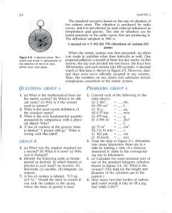
Development history To meet the needs of the times, we've continued to develop technology continuously as the leading air conditioning manufacturer in the world.
General Catalogue * VRV is a trademark of Daikin Industries, Ltd.
02
Expansion of the country of sale Sales is undergoing in more than 70 countries
Europe Italy France Germany Spain Russia UK
Austria Belgium Bulgaria Croatia Cyprus Czech
Lithuania Macedonia Netherlands Poland Portugal Finland
Greece Hungary Ireland Romania Serbia Slovakia
Sweden Switzerland Turkey Ukraine
Asia
Middle East
Africa South Africa Algeria Burkina Faso Egypt Ivory Coast Senegal Sudan
UAE Saudi Arabia Bahrain Jordan Oman Qatar
Japan China
Korea Taiwan
USA Mexico
Oceania
Asia India Vietnam Thailand Indonesia Malaysia Singapore
North America
Cambodia Myanmar Philippine Maldives Nepal Seychelles Sri Lanka
Canada Puerto Rico
South America
Australia Fiji New Caledonia New Zealand Tahiti
Brazil Argentina Chile Colombia Panama Peru
The influence of VRV - Central system market in Japan 140,000
350,000 35,000
Fan coil unit
120,000
250,000 25,000
100,000
200,000 20,000
80,000
150,000 15,000
60,000
Chiller
100,000 10,000
40,000
VRV
50,000 5,000 0 0
Number of production (Unit)
Number of production (Unit)
300,000 30,000
20,000 0
1990
1995
2000
2005
2009
Source) -Chiller & Fan coil unit: Japan Refrigeration & Air -conditioning Institute -VRV : DAIKIN: Estimated by DAIKIN
03
04
Wide variety of series models to supply total air solutions
S SERIES
Heat Pump
From home to large buildings, and from newly constructed to renovated buildings, VRV IV system meets a wide range of air conditioning needs and supplies total air solutions.
P.63 Especially designed for residential, small offices and shops VRV Ⅳ S series is the system that aims to provide sufficient capacity, along with the compact size required by residential, small offices and shops. Outdoor units are designed to be slim and space saving, and offer 6 models to select from, providing the power that suits your needs.
RXYMQ-A Lineup
3.5
class
Heat Pump
4
5
6
8
9
P.9 Heat Recovery
REYQ-T Lineup
class
High-COP Type
P.73
Maximum comfort via simultaneous cooling and heating Heat Recovery series enables simultaneous operation of cooling and heating within a single refrigerant piping circuit by controlling the BS unit. This series also substantially improves energy efficiency by recycling exhaust heat.
8 10 12 14 16 18 20 22 24 26 28 30 32 34 36 38 40 42 44 46 48 50 52 54 56 58 60
VRV III-Q series, a replacement VRV unit, can be installed using existing refrigerant piping, so renovation of the air conditioning system can be carried out quickly and smoothly. This minimises inconveniences to activities and users in the building.
RQYQ-P RQCEQ-P Lineup
class
Standard Type
For quick & high quality replacement use
Heat Pump / Heat Recovery
Heat Pump
5
8 10 12 13 14 16 18 20 22 24 26 28 30 32 34 36 38 40 42 44 46 48
Heat Recovery
P.31 Cooling Only / Heat Pump
RX(Y)Q-T Lineup
class
High-COP Type
05
Achieves excellent performance to meet the needs in various buildings Next generation VRV IV series offers improved energy savings, comfort, and ease of installation to meet an ever wider variety of needs. It also enables a mixed combination of VRV indoor units and residential indoor units all in one system, opening the door to stylish and quiet indoor units.
6 8 10 12 14 16 18 20 22 24 26 28 30 32 34 36 38 40 42 44 46 48 50 52 54 56 58 60
W SERIES
Heat Pump / Heat Recovery
class
Standard Type
Heat Pump
Space Saving Type
Heat Recovery
6
8
10
12
Water cooled system suitable for tall multistoried buildings Water cooled VRV IV series utilises water as a heat source. The temperature of heat source water can be 10°C to 45°C, and outdoor air temperature does not affect heating capacity. The outside unit is compact and saves space in the machine room.
RWEYQ-T Lineup
P.85
14
16
18
20
22
24
26
28
30
32
34
36
06
Wide range indoor unit lineup creating various comfortable airflow VRV indoor units Type
20
25
32
40
50
63
71
80
100
125
140
145
160
180
200
250
Model Name Capacity Range(kW) 2.2
2.8
3.6
4.5
5.6
7.1
8.0
9.0
11.2
14
16
16.2 18.0
20
22.4
28
25
31.3
40
50
62.5
71
80
100
125
140
145
180
200
250
Capacity Index Ceiling Mounted Cassette (Round Flow with Sensing)
FXFQ-S
Ceiling Mounted Cassette (Round Flow)
FXFQ-P
Ceiling Mounted Cassette (Compact Multi Flow)
FXZQ-A2
4-Way Flow Ceiling Suspended
FXUQ-A
Ceiling Mounted Cassette (Double Flow)
FXCQ-M
Ceiling Mounted Cassette Corner
FXKQ-MA
Slim Ceiling Mounted Duct (Standard Series)
Slim Ceiling Mounted Duct (Compact Series) Middle Static �Pressure Ceiling �Mounted Duct Ceiling Concealed (Duct)
Ceiling Mounted Duct
160
Ceiling Mounted Cassette (Compact Multi Flow)
Slim Ceiling Mounted Duct
Model Name
Capacity Range(kW) Capacity Index
20 2.2 20
25 2.5 25
35 3.5 35
50 5.0 50
60 6.0 60
71 7.1 71
FFQ-B CDKS-EA CDXS-EA CDKS-C FDXS-C
CTXG-P
Wall Mounted
FTKS-K FTXS-K FTKS-KA FTXS-KA
FXDQ-NB
Floor Standing
FXDQ-SP Floor/Ceiling Suspended Dual
FXSQ-P
FVXS-K
FLXS-B
FLXS-G Note: For indoor units that can be connected, please refer to the indoor unit product lineups associated with each outdoor unit series.
FXDYQ-MA
FXMQ-P
FXMQ-MF
Ceiling Suspended
FXHQ-MA
Wall Mounted
FXAQ-P
Floor Standing
FXLQ-MA
Concealed Floor Standing
FXNQ-MA
Heat Reclaim Ventilator
20
Type
FXDQ-PB
Outdoor-Air Processing Unit
Heat Reclaim Ventilator with DX-Coil and Humidifier
Residential indoor units with connection to BP units
VKM-GA(M)
Airflow rate 500-1000 m3/h
VAM-GJ
Airflow rate 150-2000 m3/h
Note: For indoor units that can be connected, please refer to the indoor unit product lineups associated with each outdoor unit series.
07
08
Maximum comfort via simultan eous cooling and heating
Heat Recovery
VRV IV
Heat Recovery
Offers simultaneous cooling and heating operation on the same floor!
REYQ-T Cooling operation for rooms significantly heated by sun
Heat Recovery
8 class-60 class (22.4 kW)
(168 kW)
What is Heat Recovery Air Conditioner?
Modern office buildings are highly airtight and subject to an increasing heat load due to the use of computers, lighting equipment and other office equipment. In these buildings some rooms may require artificial cooling even in winter, depending on the amount of sunshine received and the number of people in the room. In order to meet such requirements the Heat Recovery Series enables the simultaneous operation of cooling and heating by controlling the BS unit that switches cooling and heating. This series also substantially improves energy efficiency by recycling waste heat.
Heat recovery operation mode 28 kW
7 kW
7 kW
7 kW
7 kW
No.1
No.2
No.3
No.4
Individual BS unit Indoor unit
(cooling and heating operation)
(C)
Heat radiation operation (all cooling operation)
(A)
(D)
(B)
cooling
cooling
cooling
cooling
heating
heating
Heat absorption tendency heat recovery operation
cooling heating Outdoor air processing air conditioning
heating
cooling
heating
heating
cooling
heating
Individual office
Able to cater to individual heating and cooling requirement
Provides heating and annual cooling depending on space area
BS unit (Individual type/Centralised type)
heating
heating
heating
Centralised BS unit
Heat recovery
Heat pump
Individual BS unit
Gas piping
heating
Individual BS unit
Outdoor unit
Indoor unit
Indoor unit
Indoor unit
* For indoor units used for cooling only (do not connect to BS unit when using for heat recovery), total capacity index must be 50% or less than the capacity index of the outdoor units.
High and low pressure gas piping
Suction gas piping
Liquid piping
Note: Operation modes (A) and (E) are applicable when the outdoor temperature is 35°C and 7°C respectively; The other modes are applicable under typical outdoor conditions.
09
cooling office
Winter season (Hotel)
Individual BS unit
(E) cooling
heating
heating
(all heating operation)
cooling
heating
cooling corridor
Heat absorption operation
(mainly cooling, part heating operation)
Individual BS unit
By adding suction gas piping and a BS unit (sold separately), simultaneous cooling and heating operation can be provided by a single system.
(mainly heating, part cooling operation) Heat absorption
cooling
Heat radiation tendency heat recovery operation
Heat radiation
cooling
Centralised BS unit
Difference between the load of cold air and heat from room is large Can be use with the outdoor air processing air conditioning
cooling
Heat radiation
Individual BS unit
Winter season (Office Building) Heat recovery operation
Outdoor unit
Increasing demand for simultaneous cooling and heating needs heating
Operation mode
Heating operation for rooms not significantly heated by sun
Liquid piping Outdoor unit
By adding suction gas piping and a BS unit...
Indoor unit (Heating)
Indoor unit (Cooling)
Indoor unit * (Cooling only)
Heat recovery operation!
10
Excellent Operational Performance
Heat Recovery
Ease of installation
With its enhanced lineup of 2 types-High-COP and Standard types, VRV Ⅳ Heat Recovery series outdoor units offer a higher capacity up to 60 class (168 kW) to meet an ever wider variety of needs.
Compact & lightweight design
Highly-integrated VRV Ⅳ system offers compact outdoor units to achieve maximum utilisation of the installation space.
VRV
1,300 mm
765 mm
930 mm
VRV
12 class(33.5 kW)
12 class(33.5 kW)
14, 16, 18, 20 class
11
Product Weight 230 kg
30% Decrease
Sound level(dB(A))
8 class
10 class
12 class
14 class
16 class
58
58
60
62
63
56
57
59
60
61
Up to 48 class
Up to 60 class
1 type only
2 types of High-COP type and Standard type
Streamlined air grille It promotes the discharge of swirling airflow, further reducing the pressure loss.
Mo/C
Streamlined scroll fan The sharp edge of each fan blade has a certain curvature, reducing both the vibration and the pressure loss. Streamlined scroll fan Illustrated fan
1˜ 2 dB(A) reduction than conventional model
Nighttime quiet operation function
Outdoor PCB automatically memorises the time when the peak outdoor temperature appears. It will enable quiet operation mode after 8 h*1, and return to normal mode after it keeps for 9 h*2. *1. 8 h is the initial setting with 6 h or 10 h also available. *2. 9 h is the initial setting with 8 h or 10 h also available. *3. In case of 10 class outdoor unit during cooling operation.
Peak in outdoor temperature
Capacity (%)
Without increasing operation sound, advanced analytical technologies are utilised to optimise fan design and increase airflow rate and high external static pressure.
Standard Type
Product Weight 331 kg
100
Load (%)
Improve heat exchanger efficency, helps to reduced operation sound.
Large airflow, high static pressure and quiet technology
High-COP Type
28% Decrease
Lower operation sound
VRV
class
Installation Space 0.71 m2
Comfort
Up to 20 class
Multiple Outdoor Units
Lineup
(33.5 kW)
Installation Space 0.99 m2
Night mode
50
9 hrs
8 hrs
0
Operating sound (dB)
Up to 16 class
8, 10, 12 class
765 mm
12 class
12 class (33.5 kW)
VRV
Single Outdoor Unit
8, 10, 12, 14, 16 class
VRV IV
2 types up to 60 class
Heat Recovery
Enhanced Lineup
57
45
8:00
Enable night mode 12:00
16:00
20:00
VRV IV
min. 45 0:00
*3
dB(A) 4:00
8:00
Note: · This function is available in setting at site. · The operating sound in quiet operation mode is the actual value measured by our company. · The relationship of outdoor temperature (load) and time shown above is just an example.
12
Excellent Operational Performance
The flexibility of simultaneous cooling and heating operation has been further enhanced by various advanced technologies.
Higher Coefficient of Performance (COP)
It has become essential for air conditioning manufacturers to develop systems that provide high energy savings. We at Daikin have made great efforts in this field, and the VRV Ⅳ system delivers highly efficient performance, contributing to high energy savings. Cooling Operation COP 4.50
3.98
3.87
Comparison of 12 class system ( During simultaneous cooling and heating operation )
3.67
Conventional model (VRV
3.46
3.50
3.00
8 class
10 class
12 class
Development of a highly efficient heat exchanger utilising of a two-split structure
In a conventional system, two heat exchanger panels are utilised: one is used as an evaporator; while the other is used as a condenser. In the newly developed system, a two-split structure is utilised, with one panel split into two parts (top and bottom) at an optimal ratio depending on the capacity required for simultaneous cooling and heating operation. Heat radiation loss has been minimised, and the heat recovery efficiency and partial load characteristics have been improved.
4.34
4.00
VRV IV
Energy saving
Heat Recovery
Heat Recovery
14 class
16 class
*Cooling operation conditions: Indoor temp. of 27ºCDB,19ºCWB, and outdoor temp. of 35ºCDB.
)
The size has been reduced by using four heat exchanger panels.
The heat exchanger panel utilises a two-split structure (top and bottom), achieving higher heat recovery efficiency than the conventional model.
Two heat exchanger panels are used. Heat radiation loss from the condenser is high.
Heating Operation COP 4.50
4.40
4.32 4.07
Indoor and outdoor heat balance (conceptual image)
4.17
[ Indoor unit side ]
3.94
4.00
[ Outdoor unit ]
Cooling load (heat absorption)
Conventional model (VRV
3.50
3.00
8 class
10 class
12 class
14 class
16 class
*Heating operation conditions: Indoor temp. of 20ºCDB, and outdoor temp. of 7ºCDB, 6ºCWB.
The heat recovery system utilises waste heat, achieving outstanding energy conservation performance.
2
Outdoor unit
BS unit
1 Cooling
13
1
The (cold) waste heat from heating is used for the cooling operation.
Indoor unit
Heating
2
The waste heat from cooling is used to generate heat that is needed for heating operation while conserving electricity.
Heat Heating load recovery (heat radiation)
The thermal load that cannot be recovered needs to be radiated from the outdoor unit.
)
The optimal condensation capacity can be attained.
The condenser is large, resulting in unnecessary heat radiation.
Heat loss control
Heat loss
Condenser
Evaporator
Heat Recovery Link control to reduce the heat loss
Heat loss is minimised by interlocking the heat exchanger switching, motor-operated valves, compressors, and fans, which are conventionally controlled independently during simultaneous cooling and heating operation, leading to a significant increase in efficiency.
VRV
Refrigerant circuit is balanced based on the independent control of each elements
Fan
Switch HE
EV
occurred heat loss Comp.
Interlocking operation with each elements in order to reduce energy Improvement of Heat recovery
Fan
Switch HE
EV
Comp.
14
VRT-Variable Refrigerant Temperature
Basic mode is selected to maintain optimal comfort. VRT is selected to save energy and prevent excessive cooling or heating.
The new VRV IV system now features VRT technology. VRT automatically adjusts refrigerant temperature to individual building and climate requirement, thus further improving annual energy efficiency and maintaining comfort. With this excellent technology, running costs are reduced.
During cooling, the refrigerant evaporating temperature (Te) is raised to minimise the difference with the condensing temperature. During heating, condensing temperature (Tc) is lowered to minimise the difference to the evaporating temperature. Compressors work less, and this reduces power consumption.
Capacity priority
Fixed Refrigerant Temperature
(During heating)
Compressor
Evaporator
Fixed Te/Tc - Standard control
Evaporator
Cooling load & capacity
Required capacity changes as air conditioning load changes according to outdoor temperature.
25%
Powerful Mode Reaction speed
25℃
30℃
35℃
Outdoor Temp.
Automatic control adjusts evaporating temperature to heat load change.
High
VRT
Low
COP
Energy efficiency is improved without sacrificing comfort.
Without VRT
20℃
15
25℃
30℃
35℃
Outdoor Temp.
Indoor Temp. (ºC)
Fast
Quick Mild
Start of cooling
Set temperature
Fast
Time Medium
Mild Mode
Eco Mode
Reaction speed Medium (Default setting on VRV IV)
Powerful mode
Powerful
Very Fast
Unable to change Te
• Can boost capacity above 100% if needed. The refrigerant temperature can go lower in cooling (higher in heating) than the set minimum (maximum in heating). • Gives priority to very fast reaction speed. The refrigerant temperature goes down (or up in heating) fast to keep the room setpoint stable.
Quick mode
• Gives priority to fast reaction speed. The refrigerant temperature goes down (or up in heating) fast to keep the room setpoint stable.
Mild mode
• Gives priority to efficiency. The refrigerant temperature goes down (or up in heating) gradually giving priority to the efficiency of the system instead of the reaction speed.
Recommended for use in these situations Cooling only regions having differences in daily temperature.
Outdoor Temp. (ºC)
High
Automatic control to adjust temperature
Without VRT
20℃
In case of fixed evaporating temperature, excessive cooling, thermo on-off loss, and other inefficiencies occur.
Reaction speed
VRT offers quicker cool down to shorten uncomfortable pull down time.
25
Low
Refrigerant evaporating temp. / Te(℃)
VRT
Outdoor Temp.
Fixed Te
Quick Mode
Very Fast
30
35℃
Fixed target Te
Floating Te/ Tc
100%
30℃
Floating target Te/Tc depending on heat load (Default setting on VRV IV)
Compressor
Typical changes in evaporating temperature and COP depending on changing indoor load
25℃
High Sensible Mode
Selecting VRT enables operation to be optimised for either energy efficiency or rapid cooling/heating.
Condenser Indoor unit heat exchanger
Evaporating temperature raised Compressor workload reduced
20℃
Auto Mode
Condensing temperature lowered Compressor workload reduced
Condenser
Capacity changes to match heat load
Variable Refrigerant Temperature
Basic Mode
Refrigerant cycle (During cooling)
Indoor unit heat exchanger
Energy saving priority
40 35
Av. max. temp.
Cooling/heating regions having periods of mild outdoor temperatures.
Av. daily temp. difference
Outdoor Temp. (ºC)
How is energy reduced?
VRV IV
Customise your VRV system for optimal annual efficiency
Fine control to match user preference available through mode selection
Heat Recovery
State-of-the-art energy saving technology
Heat Recovery
30 25 20 15 0
Av. min. temp. (Typical example)
Mar.
Jun.
Sep.
VRT is particularly effective at night when temperatures are low.
Dec.
40 35 30 25
Heating period
Intermediate period
Intermediate Heating period period
Cooling period
Av. max. temp.
20 15 0
(Typical example)
Av. min. temp. Mar.
Jun.
Sep.
Dec.
VRT is particularly effective during the intermediate periods.
* VRT is only available during either all cooling operation or all heating operation.
16
Enhanced Lineup of BS Units
Individual BS unit
Recommended for large spaces or areas subject to frequent layout change
PS BSQ100AV1 BSQ160AV1 BSQ250AV1
Compact and lightweight design 10
Individual BS unit
Individual BS unit
Individual BS unit
Individual BS unit
Individual BS unit
Indoor unit
Enhanced Line up 8
Individual BS unit
Recommended for areas which have many small rooms
PS
BS4Q14AV1 BS6Q14AV1 BS8Q14AV1 BS10Q14AV1 BS12Q14AV1 BS16Q14AV1
12
Conventional Centralised BS Unit
16
Compared to conventional BS unit (6 branch) BS unit size
reduced by 65%
Centralised BS Unit
BS unit weight
58 connecting point
Centralised BS unit
Faster installation of centralised BS unit thanks to open connection
reduced by 73%
Installation and maintenance work have been made easier through the integration of multiple BS units. Individual BS unit
EV
Centralised BS unit
Centralised BS unit
6
EV
Individual BS unit
Centralised BS unit
4
Combined use of a centralised BS unit and individual BS units meets the needs of many design plans.
Indoor unit
Compact and flexible installation Flexible design Low noise
No. of branches
VRV IV
Individual and centralised BS unit allow greater design flexibility.
Heat Recovery
Heat Recovery
22
connecting point
Time saving! No need to cut the pipe before brazing
Cut and braze the pipe (for indoor units bigger or equal to 7.1 kW (63 class))
(for indoor units smaller or equal to 5.6 kW (50 class))
Lower transient sound New BS units achieve lower transient sound level than conventional BS units.
Individual BS unit
Centralised BS unit Maximum transient sound
*Centralised BS unit requires drain pipe
Greater design flexibility achieved by increasing the connection capacity range Centralised BS unit Increased from
2.2–16.0 kW
(Up to 11.2 kW in the conventional system)
17
Centralised BS unit 4 branch
6 branch
8 branch 47
New BS units
Sound level (dB(A))*
45
47
Conventional BS units
Sound level (dB(A))*
51.5
53.5
Individual BS unit
10 branch 12 branch 16 branch 48
48
49
100 type
160 type
40
45
45
45.5
46.5
47.5
250 type
*Anechoic chamber conversion value, measured at a point 1 m downward from the unit centre.
Centralised BS unit By merging two branches Adaptable up to
28.0 kW
18
More Flexible System Design Long piping length
Connection ratio
Connection capacity at maximum is 200%.
The long piping length provides more design flexibility, which can match even large-sized buildings.
Conditions of VRV indoor unit connection capacity
Multiple use Equalising pipe is no longer required between the outdoor units.
Max. actual piping length
Applicable VRV indoor units
k
165 m
Single outdoor units
q
Max. equivalent piping length
m
l
190 m
Double outdoor units First indoor branch
a
p First outdoor branch
Max. total piping length
Triple outdoor units
Connection ratio
50%–200%
FXDQ, FXSQ, FXMQ-P, FXAQ models
Connection ratio =
Total capacity index of the indoor units Capacity index of the outdoor units
VRV IV
More options for equipment placement
Heat Recovery
Heat Recovery
Other VRV indoor unit models*1
200%
200%
160% 130%
*1 For the FXFQ25P and FXFQ25S models, maximum connection ratio is 130% for the entire range of outdoor units.
f
Note: If the operational capacity of indoor units is more than 130%, low airflow operation is enforced in all the indoor units.
*Refer to page 27 for outdoor unit combination details.
b
1000 m
Single use
a
Max. level difference between the indoor units 3
First indoor branch
r
15 m higher than VRV
g
f b
c
h d
e
Max.
90 m 2 Max.
30 m
3
Colours in the diagram above are merely for identifying pipes referenced with symbols such as a .
Actual piping length
Example
Equivalent piping length
Refrigerant piping length
165 m
a+f+g+h+i
190 m
Total piping length
1000 m
a+b+c+d+e+f+g+h+i
—
Between the first indoor branch and the farthest indoor unit
90 m*
f+g+h+i
—
k+p,l,m
13 m
Between the outdoor branch and outdoor unit
Between the outdoor units (Multiple use) Maximum allowable level difference
1
10 m Level Difference
Example
5m
q
30 m
Between the indoor units Between the outdoor units and the indoor units
More options in the opening/angle of louvre Outstanding heat dissipation effect in both hierarchical and intensive arrangement
i
s
Maximum allowable piping length
78.4 Pa
Wide operation temperature range The versatile operation range of the VRV IV system works to reduce limitations on installation locations. The operation temperature range for heating goes all the way down to -20˚C, while cooling can be performed with outdoor temperatures as high as 43˚C. Both these achievements are due to the employment of a high-pressure dome-type compressor.
50 40
43˚CDB
30 20 10 0 -10
-5˚CDB Cooling
Outdoor temperature (°CWB)
30 m
VRV IV outdoor unit condenser fans are able to achieve external static pressures of up to 78.4 Pa, ensuring efficient heat dissipation and stable operations.
2
Outdoor temperature (°CDB)
between the outdoor units and the indoor units
90 m
High external static pressure
*The rest of indoor units are the same as for single use.
Max. level difference
20
15.5˚CWB
15.5˚CWB
10 0 -10
-6˚CWB
-20
Cooling & Heating
-20˚CWB Heating
s
If the outdoor unit is above.
90 m
2
r
If the outdoor unit is below.
90 m
2
r
1. No special requirements up to 40 m. The maximum actual piping length can be 90 m, depending on conditions. Various conditions and requirements have to be met to allow utilisation of 90 m piping length. Be sure to refer to the Engineering Data Book for details of these conditions and requirements. 2. When level differences above 50 m if the outdoor unit is above the indoor unit and 40 m if the outdoor unit is below the indoor unit, a dedicated setting on the outdoor unit is required. Refer to the Engineering Data Book and contact your local dealer for more information. 3. When level differences are 15 m or more, maximum actual piping length must be 120 m.
19
20
Reliable and Stable System
Efficient automatic test operation
Daikin VRV IV system incorporates a simplified and efficient test operation function, not only greatly accelerating the installation process, but effectively improving the field setting quality as well. Automatic check
Automatically checks the wirings between outdoor units and indoor units to confirm whether there is a defective wiring.
Outdoor unit sequencing technology
Automatic sequencing operation
During start-up, Daikin VRV IV unit sequencing operation will be automatically enabled to ensure balanced operation of each outdoor unit to improve longevity of equipment and stable operation.
Stage 1
Wiring check
Optimises operations to suit field piping lengths.
Piping check
Automatically check whether the stop valve in each outdoor unit is in normal status to ensure the smooth operation of air conditioning system.
Stage 2
Automatic sequencing Priority:
Priority:
VRV IV
Multiple advanced features ensuring more accurate test operation and stable system
Heat Recovery
Heat Recovery
Stage 3
Automatic sequencing Priority:
Stop valve check
Simplified commissioning and after-sales service
Function of information display by luminous digital tube
VRV IV system utilises 7-segment luminous digital tubes to display system operation information, enabling the operational state to be visually displayed whilst facilitating simplified commissioning and after-sales service.
7-segment digital display
Displays system operation information directly
Conventional LED display Figures out system operation information by reading light emitting state of different diodes, which is both inefficient and fallible.
Double backup operation functions responding resiliently to various unexpected situations
Double backup operation functions
Daikin VRV IV system boasts double backup operation functions, which can secure the use of air conditioners in this area to the greatest extent by emergently enabling double backup operation functions even if failure occurs in a set of air conditioning equipment. In the event of a failure, emergency operation can be conveniently enabled to allow the remaining system to operate in a limited fashion.
Unit backup operation function
Compressor backup operation function
If malfunction occurs in an outdoor unit... Emergency operation can be conveniently set and enabled by the remote controller for indoor unit (for systems composed of two or more outdoor units ).
If malfunction occurs in a compressor... Emergency operation can be easily set and enabled by the outdoor unit (for a single outdoor unit system REYQ14-20TY1 models).
Compliant with the RoHS Directive*
We have been making efforts to facilitate the transition to using RoHS Directive*-compliant materials for system parts. * RoHS Directive The RoHS (Restriction of Hazardous Substances (in electrical and electronic equipment)) Directive is an environmental directive enacted to regulate the use of designated chemical substances (lead, cadmium, hexavalent chromium, mercury, polybrominated biphenyls and polybrominated diphenylether) in electrical equipment. All household products subject to this Directive and sold in Europe from July 1, 2006 are legally bound to comply with the RoHS Directive.
21
22
Excellent Performance
Large capacity inverter compressor using high tension strength material, resulting in 12 class (33.5 kW) compressor utilising an 8 class (22.4 kW) casing.
Various advanced control main PC board
SMT* packaging technology
SMT packaging technology adopted by the whole computer control panel improves the anti-clutter performance.
Computer control board surface adopting SMT packaging technology
Conventional computer control board surface
VRV IV
Large capacity all DC inverter compressor in compact casing
Heat Recovery
Heat Recovery
Advanced Technologies Achieve
Protects your computer boards from the adverse effect of sandy and humid weather.
Development of high strength material
Compact high efficiency concentrated winding motor
Gives 2.4 times tensile strength compare to conventional material New Material: 600 MPa Conventional Material : 250 MPa Increase compression chamber volume by using thin spiral design.
Distributed winding motor Concentrated winding motor (Current 8 class(22.4 kW) (New 12 class(33.5kW) compressor) compressor)
Computer control board
Coil end
Small sizing coil end using concentrated winding, reduce copper loss (winding resistance). Improve motor efficiency in low rpm range (improve intermediate efficiency).
SMT packaging material
*SMT: Surface mounted technology
Refrigerant cooling technology, ensures stability of PCB temperature Improved inner design to increase smooth airflow Downsize electric component, re-locate to dead space of bell mouth side to decrease airflow resistance.
As a result of having thinned wall thickness of the scroll, compression chamber volume increase 50%
Bell mouth
Electric Component Space
VRV
Highly integrated heat exchanger
Improve performance by increasing heat exchanger area while maintaining the same installation space. Realise highly integrated heat exchanger performance (increase row, reduce fin pitch) by reducing of airflow resistance which changes cooling tube to Ø7.
VRV
Roof terrace temperature in summer is over 40 C, seriously affecting inverter cooling efficiency, resulting in decline of inverter operating speed. Finally device parts response speed is reduced.
18,20 class (50,56 kW)
3 row with small pipe design, increases heat transfer efficiency Fine Louvre Fin
23
Waffle Fin
Change fin shape from fine louvre to waffle fin. Fin pitch can be reduced fin pitch from 2.0 mm to 1.4 mm, to realise unit efficiency which increased heat exchanger area.
16 class (45 kW)
Heat exchanger Contribution of COP area (cooling)
24%UP
108.5%
Control board failure ratio at stable operation is reduced.
Improve reliability at high ambient temperature It is possible to cool the inverter power module stability even at high ambient temperature. This helps to keep air-conditioning capacity and also reduces failure ratio.
24
Wide Range of Choices Enhanced lineup of 2 types with maximum capacity of 60 class (168 kW). With its enhanced lineup of 2 types, VRV IV Heat Recovery series outdoor units offer a higher capacity up to 60 class (168 kW) to meet an ever wider variety of needs. The single outdoor unit has only 2 different shapes and dimensions, not only simplifying the design process, but also bringing the system design flexibility to a new level. Outdoor units with anti-corrosion specifications (-E type on request) are designed specifically for use in areas which are subject to salt damage and atmospheric pollution.
High-COP Type
Triple Outdoor Units
Double Outdoor Units 16, 18, 20 class
Indoor Units TypeType
Ceiling Mounted Ceiling Mounted Cassette (Round Cassette(Round Flow withSensing) Sensing) Flow with
71 71
80 80
9.0 9 80 80
100 250 100 125 125 140 140 145145 160180180200200 250
11.2 11.2
14 14
1616 16.2 22.4 2828 16.218.020 20 22.4
100 250 100 125 125 140 140 145145 160180180200200 250
FXFQ-SVM FXFQ-SVM
Ceiling MountedCassette Ceiling Mounted Cassette FXFQ-PVE FXFQ-PVE (Round Flow) (Round Flow) Ceiling Mounted Ceiling Mounted CassetteFXZQ-A2VEB Cassette FXZQ-A2VEB (Compact Multi (Compact MultiFlow) Flow) 4-Way Flow 4-Way Flow Ceiling Suspended Ceiling Suspended
24, 26, 28, 30, 32 class
20 20 25 25 32 32 40 40 5050 6363
Model Name Capacity Capacity Range(kW) 7.1 8.0 Range(kW) Model Name 2.2 2.22.8 2.8 3.63.6 4.54.5 5.65.6 7.1 8 Capacity Index 20 25 31.3 40 50 62.5 71 Capacity Index 20 25 31.25 40 50 62.5 71
VRV IV
Outdoor Units - Heat Recovery
Heat Recovery
Heat Recovery
FXUQ-AVEB FXUQ-AVEB
Ceiling Mounted
Ceiling Mounted Cassette FXCQ-MVE Cassette FXCQ-MVE (Double Flow) (Double Flow) Ceiling Mounted Ceiling Mounted Cassette Corner Cassette Corner
REYQ16THY1(E) REYQ18THY1(E) REYQ20THY1(E)
REYQ24THY1(E) REYQ26THY1(E) REYQ28THY1(E)
Slim Ceiling Slim Ceiling Mounted Duct Mounted Duct (Compact Series)
Standard Type
(Compact Series)
Double Outdoor Units
Single Outdoor Units 8, 10, 12 class
Slim Ceiling Slim Ceiling Mounted Duct Mounted Duct (Standard Series) (Standard Series)
REYQ30THY1(E) REYQ32THY1(E)
14, 16, 18, 20 class
22, 24 class
26, 28, 30 class
Middle Static
32, 34, 36 class
FXKQ-MAVE FXKQ-MAVE FXDQ-PBVE
FXDQ-PBVE
FXDQ-NBVE
FXDQ-NBVE(900/1,100 mm width type)
(900/1,100 mm width type)
FXDQ-SPV1
FXDQ-SPV1
Pressure Ceiling Middle Static �Pressure Mounted Duct Ceiling �Mounted Duct
FXSQ-PVE
Ceiling Concealed
FXDYQ-M(A)V1
Ceiling Concealed (Duct) (Duct)
(700 mm width type) (700mm width type)
FXSQ-PVE
FXDYQ-MAV1
FXMQ-PVE Ceiling Mounted Duct
Ceiling Mounted Duct
REYQ8TY1(E) REYQ10TY1(E) REYQ12TY1(E)
REYQ14TY1(E) REYQ18TY1(E) REYQ16TY1(E) REYQ20TY1(E)
Triple Outdoor Units 38, 40 class
REYQ22TY1(E) REYQ24TY1(E)
42, 44 class
REYQ26TY1(E) REYQ28TY1(E) REYQ30TY1(E)
REYQ32TY1(E) REYQ34TY1(E) REYQ36TY1(E)
46, 48, 50, 52, 54, 56, 58, 60 class
FXMQ-PV1A
FXMQ-MFV1
Ceiling Suspended
FXHQ-MAVE
Outdoor-Air Processing Unit
Ceiling Suspended Wall Mounted
Floor Standing
Floor Standing
Lineup
class High-COP Type
REYQ42TY1(E) REYQ44TY1(E)
REYQ46TY1(E) REYQ52TY1(E) REYQ58TY1(E) REYQ48TY1(E) REYQ54TY1(E) REYQ60TY1(E) REYQ50TY1(E) REYQ56TY1(E)
FXMQ-MVE9
Outdoor-Air Processing Unit
Wall Mounted
REYQ38TY1(E) REYQ40TY1(E)
FXMQ-PVE
Concealed Floor Standing
Concealed Floor HeatStanding Reclaim Ventilator
with DX-Coil and Heat Reclaim Ventilator Humidifier
with DX-Coil and Heat Reclaim Humidifier Ventilator
Heat Reclaim Ventilator
FXMQ-MFV1 FXHQ-MAVE
FXAQ-PVE
FXAQ-PVE FXLQ-MAVE
FXLQ-MAVE FXNQ-MAVE
FXNQ-MAVE VKM-GA(M)V1
Airflow rate 500-1000 m3/h
VKM-GA(M)V1 VAM-GJVE
VAM-GJVE
Airflow rate 500-1000 m3/h Airflow rate 150-2000 m3/h
Airflow rate 150-2000 m3/h
Standard Type
25
26
Specifications
kW
Capacity index
Model name
Combination
16
44.8
400
REYQ16TH
REYQ8T x 2
20
55.9
500
REYQ20TH
REYQ8T + REYQ12T
26
72.8
650
REYQ26TH
REYQ8Tx 2 + REYQ10T
50.4
18
67.2
24
78.3
28
83.9
30
89.4
32
450 600 700 750 800
REYQ18TH
REYQ24TH REYQ28TH REYQ30TH REYQ32TH
REYQ8T + REYQ10T
Outdoor unit multi connection piping kit*1
BHFP26P90
REYQ8T x 3
REYQ8Tx 2 + REYQ12T
REYQ8T+ REYQ10T+ REYQ12T
Total capacity index of 2 connectable indoor units*
Maximum number of 2 connectable indoor units*
200 to 520 (640)
26 (32)
250 to 650 (800)
32 (40)
325 to 845 (845) 350 to 910 (910)
42 (42) 45 (45)
400 to 1,040 (1,040)
52 (52)
225 to 585 (720)
29 (36)
300 to 780 (780) BHFP26P136
REYQ8T+ REYQ12Tx 2
39 (39)
375 to 975 (975)
48 (48)
Note: *1. The outdoor unit multi connection piping kit (separately sold) is required for multiple connection.
High-COP Type
REYQ16THY1(E) REYQ8TY1(E) REYQ8TY1(E)
MODEL Combination units
–
Power supply kcal/h Cooling capacity
Compressor
Standard Type Class
kW
Capacity index
8
22.4
200
10 12 14 16 18 20 22 24
28.0 33.5 40.0 45.0 50.0 56.0 61.5
67.0
26
73.5
30
83.5
28 32 34 36 38 40 42 44 46 48 50 52 54
56 58 60
78.5 90.0 95.0 101
106 112 118
124 130 135 140 145 150
156 162 168
250 300 350 400 450 500 550 600 650 700 750 800 850 900 950
1,000 1,050 1,100 1,150 1,200 1,250 1,300 1,350 1,400 1,450 1,500
Model name REYQ8T
REYQ10T REYQ12T REYQ14T REYQ16T REYQ18T REYQ20T
Combination
Outdoor unit multi connection piping kit*1
Total capacity index of connectable indoor units*2
Maximum number of connectable indoor units*2
REYQ8T
–
100 to 260 (400)
13 (20)
REYQ10T REYQ12T REYQ14T REYQ16T REYQ18T REYQ20T
REYQ22T
REYQ10T + REYQ12T
REYQ26T
REYQ12T + REYQ14T
REYQ30T
REYQ12T + REYQ18T
REYQ24T REYQ28T REYQ32T REYQ34T REYQ36T REYQ38T REYQ40T REYQ42T REYQ44T REYQ46T REYQ48T REYQ50T REYQ52T REYQ54T REYQ56T REYQ58T REYQ60T
– – – – – –
BHFP26P90
375 to 975 (1,200)
16 (25) 19 (30)
BHFP26P136
625 to 1,625 (1,625) 650 to 1,690 (1,690) 675 to 1,755 (1,755) 700 to 1,820 (1,820) 725 to 1,885 (1,885) 750 to 1,950 (1,950)
Note: *1. For multiple connection of 22 class systems and above, the outdoor unit multi connection piping kit (separately sold) is required.
*2. Values inside brackets are based on connection of indoor units rated at maximum capacity, 200% for single outdoor units, 160% for double outdoor units, and 130% for triple outdoor units. Refer to page 20 for note on connection capacity of indoor units.
14.9 8-100
17.0 7-100
kW
(3.3x1)+(3.3x1)
35 (44)
45 (56) 48 (60) 52 (64) 55 (64) 58 (64) 61 (61)
/s m³/min
Piping connections
kg dB(A) Cooling
ºCDB
Heating
ºCWB
Cooling & Heating
ºCWB
Charge Liquid
kg
9.7+9.8
215+230 61 82
9.7+9.9
215+215+215 61 82
9.7+9.7+9.7
15.9 (Brazing)
Gas
mm
28.6 (Brazing)
28.6 (Brazing)
28.6 (Brazing)
34.9 (Brazing)
High and low pressure gas
mm
22.2 (Brazing)
22.2 (Brazing)
28.6 (Brazing)
28.6 (Brazing)
REYQ26THY1(E) REYQ8TY1(E) REYQ8TY1(E) REYQ10TY1(E)
REYQ28THY1(E) REYQ8TY1(E) REYQ8TY1(E) REYQ12TY1(E)
REYQ30THY1(E) REYQ8TY1(E) REYQ10TY1(E) REYQ12TY1(E)
REYQ32THY1(E) REYQ8TY1(E) REYQ12TY1(E) REYQ12TY1(E)
267,000 78.3 75,300
286,000 83.9 80,800
305,000 89.4 86,000
Cooling capacity
Btu/h kW kcal/h
Heating capacity
kW
(3.3x1)+(3.3x1)+(4.0x1)
kW kW
Type Motor output
/s
Airflow rate Dimensions (H×W×D) Machine weight Sound level
m³/min mm kg dB(A)
Sound power
248,000 72.8 70,100
%
Cooling Heating
Casing colour
62,600
278,000 81.5 17.4 18.7 6-100
Btu/h
Capacity control
Piping connections
9.7+9.7
-5 to 43 -20 to 15.5 -6 to 15.5 R-410A
158+158+158
15.9 (Brazing)
kcal/h
Refrigerant
215+230 60 81
2,633+2,633+2,633
(1,657x930x765)+(1,657x930x765)+ (1,657x930x765)
(1,657x930x765)+(1,657x930x765) 215+215 59 80
(3.3x1)+(3.3x1)+(3.3x1)
15.9 (Brazing)
Power supply
Operation range
Ivory white (5Y7.5/1) Hermetically Sealed Scroll Type (3.3x1)+(4.0x1) (3.3x1)+(4.9x1) 2,633+3,000 2,633+2,800 158+180 158+168
256,000 75.0 15.5
12.7 (Brazing)
kW
64 (64)
158+158
213,000 62.5 13.8
67.2 64,500
mm
Combination units
Compressor
2,633+2,633
193,000 56.5 12.2
Type
MODEL
Power consumption
171,000 50.0 10.3
mm
dB(A)
Sound power
39 (48) 42 (52)
Motor output
Sound level
Refrigerant
32 (50)
Type
Machine weight
29 (45)
26 (40)
575 to 1,495 (1,495) 600 to 1,560 (1,560)
13.0 8-100
kW kW
Dimensions (H×W×D)
Operation range
550 to 1,430 (1,430)
REYQ14T + REYQ16T × 2
11.4 10-100
Cooling Heating
Airflow rate
22 (35)
525 to 1,365 (1,365)
REYQ12T + REYQ16T × 2
REYQ20T × 3
350 to 910 (1,120)
500 to 1,300 (1,300)
REYQ10T + REYQ16T × 2
REYQ18T + REYQ20T × 2
275 to 715 (880)
475 to 1,235 (1,235)
REYQ8T + REYQ10T + REYQ20T
REYQ18T × 2 + REYQ20T
250 to 650 (1,000)
450 to 1,170 (1,440)
REYQ10T + REYQ12T + REYQ18T
REYQ18T × 3
225 to 585 (900)
425 to 1,105 (1,360)
REYQ16T + REYQ20T
REYQ16T + REYQ18T × 2
200 to 520 (800)
400 to 1,040 (1,280)
REYQ16T + REYQ18T
REYQ16T × 2 + REYQ18T
175 to 455 (700)
325 to 845 (1,040)
REYQ16T × 2
REYQ16T × 3
150 to 390 (600)
300 to 780 (960)
REYQ12T × 2
REYQ12T + REYQ16T
125 to 325 (500)
%
Btu/h
Casing colour
57,800
229,000
kW
Capacity control
–
191,000 55.9 53,800
kcal/h
Power consumption
–
3-phase 4-wire system, 380–415 V, 50 Hz 43,300 48,100
REYQ24THY1(E) REYQ8TY1(E) REYQ8TY1(E) REYQ8TY1(E)
172,000 50.4 48,600
kW
*2. Values inside brackets are based on connection of indoor units rated at maximum capacity, 200% for single outdoor units, 160% for double outdoor units, and 130% for triple outdoor units. Refer to page 20 for note on connection capacity of indoor units.
REYQ20THY1(E) REYQ8TY1(E) REYQ12TY1(E)
153,000 44.8 43,000
Btu/h
Heating capacity
38,500
REYQ18THY1(E) REYQ8TY1(E) REYQ10TY1(E)
dB(A) Cooling
ºCDB
Heating
ºCWB
Cooling & Heating
ºCWB
2,633+2,633+2,800 158+158+168 215+215+230 61 82
3-phase 4-wire system, 380–415 V, 50 Hz 67,300 72,200
299,000 87.5 19.0 20.6 6-100
(1,657x930x765)+(1,657x930x765)+(1,657x930x765)
Type Charge Liquid
kg mm
321,000 94.0 20.9 22.2 5-100
Ivory white (5Y7.5/1) Hermetically Sealed Scroll Type (3.3x1)+(3.3x1)+(4.9x1) (3.3x1)+(4.0x1)+(4.9x1) 2,633+2,633+3,000 2,633+2,800+3,000 158+158+180 158+168+180 215+215+230 62 83
-5 to 43 -20 to 15.5 -6 to 15.5 R-410A
215+230+230 62 83
9.7+9.8+9.9
76,900
341,000 100 22.5 24.1 5-100
(3.3x1)+(4.9x1)+(4.9x1) 2,633+3,000+3,000 158+180+180 215+230+230 63 84
9.7+9.7+9.8
9.7+9.7+9.9
19.1 (Brazing)
19.1 (Brazing)
19.1 (Brazing)
19.1 (Brazing)
VRV IV
VRV IV Outdoor Units Heat Recovery REYQ-T
High-COP Type Class
Heat Recovery
Heat Recovery
Outdoor Unit Combinations
9.7+9.9+9.9
Gas
mm
34.9 (Brazing)
34.9 (Brazing)
34.9 (Brazing)
34.9 (Brazing)
High and low pressure gas
mm
28.6 (Brazing)
28.6 (Brazing)
28.6 (Brazing)
28.6 (Brazing)
Note:1. Models with (E) are the outdoor units with anti-corrosion specifications. Please refer to Engineering Data Book for details. 2. Specifications are based on the following conditions; •Cooling: Indoor temp.: 27°CDB, 19°CWB, Outdoor temp.: 35°CDB, Equivalent piping length: 7.5 m, Level difference: 0 m. •Heating: Indoor temp.: 20°CDB, Outdoor temp.: 7°CDB, 6°CWB, Equivalent piping length: 7.5 m, Level difference: 0 m. •Sound level: Anechoic chamber conversion value, measured at a point 1 m in front of the unit at a height of 1.5 m. During actual operation, these values are normally somewhat higher as a result of ambient conditions.
27
28
Specifications Standard Type MODEL Combination units Power supply kcal/h Cooling capacity
Btu/h kW kcal/h
Heating capacity
Btu/h kW
Power consumption
Cooling
kW
Heating
kW
Capacity control Casing colour
REYQ8TY1(E)
REYQ10TY1(E)
–
–
19,300
24,100
22.4 21,500
28.0 27,100
76,400
85,300 25.0 5.16
95,500
107,000 31.5 7.04
%
5.68 20-100
7.29 16-100
kW
3.3x1
4.0x1
/s
2,633
2,800
215 56 77
1,657x930x765 230 57 78
Type Compressor
Motor output
Airflow rate Dimensions (H×W×D)
Machine weight
Piping connections
kg dB(A)
Sound power
Refrigerant
mm dB(A)
Sound level
Operation range
m³/min
Cooling
ºCDB
Heating
ºCWB
Cooling & Heating
ºCWB
168
Charge Liquid
kg
–
–
–
–
38,700
43,000
3-phase 4-wire system, 380–415 V, 50 Hz 28,800 34,400 114,000
136,000
128,000 37.5 8.66
154,000 45.0 10.9
33.5 32,300
9.7
9.8
40.0 38,700
154,000 45.0 43,000
171,000 50.0 48,200
–
REYQ22TY1(E) REYQ10TY1(E) REYQ12TY1(E)
REYQ24TY1(E) REYQ12TY1(E) REYQ12TY1(E)
48,200
52,900
57,600
191,000
210,000
229,000
191,000 56.0 15.4 15.0 8-100
215,000 63.0 18.0
235,000 69.0 15.7
256,000 75.0 17.3
56.0 54,200
61.5 59,300
4.9x1
(3.0x1)+(3.1x1)
(3.4x1)+(3.7x1)
(3.6x1)+(5.0x1)
(4.0x1)+(6.1x1)
(4.0x1)+(4.9x1)
(4.9x1)+(4.9x1)
3,000 180
3,900 234
3,983 239
3,767 226
4,483
2,800+3,000
3,000+3,000 180+180
230 59 80
310 60 81
Ivory white (5Y7.5/1) Hermetically Sealed Scroll Type
9.9
-5 to 43 -20 to 15.5 -6 to 15.5 R-410A
11.8
1,657x1,240x765 310 61 82
11.8
342 62 83
11.8
269
1,657x1,240x765 342 65 86
11.8
16.5 8-100
168+180
REYQ30TY1(E) REYQ12TY1(E) REYQ18TY1(E)
251,000
268,000
281,000 82.5 19.6
299,000 87.5 21.7
285,000 83.5 80,400
3-phase 4-wire system, 380–415 V, 50 Hz 63,200 67,500 73.5 71,000
10.8 11-100
17.5 8-100
REYQ28TY1(E) REYQ12TY1(E) REYQ16TY1(E)
67.0 64,500
171,000 50.0 13.0 12.7 10-100
9.22 15-100
REYQ26TY1(E) REYQ12TY1(E) REYQ14TY1(E)
18.4 8-100
77,400
319,000 93.5 24.1 24.2 5-100
21.9 6-100
Ivory white (5Y7.5/1) Hermetically Sealed Scroll Type
3,000+3,900 180+234 230+310 63 84
9.9+9.9
9.9+11.8
3,000+3,983 180+239
(1,657x930x765)+(1,657x1,240x765) 230+310 63 84 -5 to 43 -20 to 15.5 -6 to 15.5 R-410A
3,000+3,767 180+226
9.9+11.8
230+342 64 85
9.9+11.8
REYQ34TY1(E) REYQ16TY1(E) REYQ18TY1(E) 81,700
307,000 90.0 86,000
324,000 95.0 91,200
(3.4x1)+(3.7x1)+ (3.4x1)+(3.7x1)
(3.4x1)+(3.7x1)+ (3.6x1)+(5.0x1)
341,000 100 26.0 25.4 5-100
(4.9x1)+(3.0x1)+(3.1x1) (4.9x1)+(3.4x1)+(3.7x1) (4.9x1)+(3.6x1)+(5.0x1)
(1,657x930x765)+(1,657x930x765) 230+230 230+230 61 62 82 83
9.8+9.9
71,800
78.5 75,300
20.0 6-100
REYQ32TY1(E) REYQ16TY1(E) REYQ16TY1(E)
3,983+3,983 239+239
362,000 106 28.4 27.7 4-100
3,983+3,767 239+226
(1,657x1,240x765)+(1,657x1,240x765) 310+310 310+342 64 65 85 86
11.8+11.8
11.8+11.8
12.7 (Brazing)
12.7 (Brazing)
12.7 (Brazing)
15.9 (Brazing)
15.9 (Brazing)
15.9 (Brazing)
15.9 (Brazing)
19.1 (Brazing)
19.1 (Brazing)
19.1 (Brazing)
19.1 (Brazing)
19.1 (Brazing)
Gas
mm
19.1 (Brazing)
22.2 (Brazing)
28.6 (Brazing)
28.6 (Brazing)
28.6 (Brazing)
28.6 (Brazing)
28.6 (Brazing)
28.6 (Brazing)
34.9 (Brazing)
34.9 (Brazing)
34.9 (Brazing)
34.9 (Brazing)
34.9 (Brazing)
34.9 (Brazing)
High and low pressure gas
mm
15.9 (Brazing)
19.1 (Brazing)
19.1 (Brazing)
22.2 (Brazing)
22.2 (Brazing)
22.2 (Brazing)
28.6 (Brazing)
28.6 (Brazing)
28.6 (Brazing)
28.6 (Brazing)
28.6 (Brazing)
28.6 (Brazing)
28.6 (Brazing)
28.6 (Brazing)
REYQ36TY1(E) REYQ16TY1(E) REYQ20TY1(E)
–
REYQ38TY1(E) REYQ8TY1(E) REYQ10TY1(E) REYQ20TY1(E)
REYQ40TY1(E) REYQ10TY1(E) REYQ12TY1(E) REYQ18TY1(E)
REYQ42TY1(E) REYQ10TY1(E) REYQ16TY1(E) REYQ16TY1(E)
REYQ44TY1(E) REYQ12TY1(E) REYQ16TY1(E) REYQ16TY1(E)
REYQ46TY1(E) REYQ14TY1(E) REYQ16TY1(E) REYQ16TY1(E)
REYQ48TY1(E) REYQ16TY1(E) REYQ16TY1(E) REYQ16TY1(E)
REYQ50TY1(E) REYQ16TY1(E) REYQ16TY1(E) REYQ18TY1(E)
REYQ18TY1(E) REYQ18TY1(E)
86,900
91,200
107,000
112,000
116,000
120,000
125,000
3-phase 4-wire system, 380–415 V, 50 Hz 129,000
553,000 162 43.8
573,000 168 46.2
Cooling capacity
Btu/h kW kcal/h
Heating capacity
Btu/h kW Cooling
kW
Heating
kW
Capacity control Casing colour
%
345,000 101 97,200
362,000 106 103,000
30.2 4-100
30.5 4-100
386,000 113 31.0
409,000 120 30.2
Type Motor output
Airflow rate Dimensions (H×W×D)
kW
(3.4x1)+(3.7x1)+ (4.0x1)+(6.1x1)
(3.3x1)+(4.0x1)+ (4.0x1)+(6.1x1)
/s
3,983+4,483
2,633+2,800+4,483
m³/min
239+269
mm
(1,657x1,240x765)+ (1,657x1,240x765)
kg
Machine weight
dB(A)
Sound level
dB(A)
Sound power
Piping connections
REYQ20TY1(E)
9.5 (Brazing)
kcal/h
Refrigerant
REYQ18TY1(E)
9.5 (Brazing)
Power supply
Operation range
REYQ16TY1(E)
mm
Combination units
Compressor
REYQ14TY1(E)
Type
MODEL
Power consumption
158
REYQ12TY1(E)
Cooling
ºCDB
Heating
ºCWB
Cooling & Heating
ºCWB
158+168+269
3-phase 4-wire system, 380–415 V, 50 Hz 96,300 101,000 382,000 112 108,000
403,000 118 114,000
31.5 4-100
32.7 4-100
471,000 138 34.7 34.6 4-100
(4.0x1)+(3.4x1)+ (3.7x1)+(3.4x1)+ (3.7x1) 2,800+3,983+3,983 168+239+239
(4.9x1)+(3.4x1)+ (3.7x1)+(3.4x1)+ (3.7x1) 3,000+3,983+3,983 180+239+239
427,000 125 31.1
450,000 132 33.0
Ivory white (5Y7.5/1) Hermetically Sealed Scroll Type (4.0x1)+(4.9x1)+ (3.6x1)+(5.0x1) 2,800+3,000+3,767 168+180+226
(1,657x930x765)+(1,657x930x765)+ (1,657x1,240x765)
423,000 124 119,000
(1,657x930x765)+(1,657x1,240x765)+ (1,657x1,240x765)
310+342 66 87
215+230+342 66 87
230+230+342 65 86
230+310+310 65 86
230+310+310 65 86
9.8+11.8+11.8
Type
-5 to 43 -20 to 15.5 -6 to 15.5 R-410A
444,000 130 125,000 495,000 145 36.9 36.2 3-100
(3.0x1)+(3.1x1)+ (3.4x1)+(3.7x1)+ (3.4x1)+(3.7x1) 3,900+3,983+3,983 234+239+239
(1,657x1,240x765)+ (1,657x1,240x765)+ (1,657x1,240x765)
REYQ52TY1(E) REYQ16TY1(E)
461,000 135 129,000
478,000 140 134,000
495,000 145 139,000
38.1 3-100
40.4 3-100
42.7 3-100
512,000 150 39.0
(3.4x1)+(3.7x1)+ (3.4x1)+(3.7x1)+ (3.4x1)+(3.7x1) 3,983+3,983+3,983 239+239+239
532,000 156 41.4
(3.4x1)+(3.7x1)+ (3.4x1)+(3.7x1)+ (3.6x1)+(5.0x1) 3,983+3,983+3,767 239+239+226
(3.4x1)+(3.7x1)+ (3.6x1)+(5.0x1)+ (3.6x1)+(5.0x1) 3,983+3,767+3,767 239+226+226
REYQ54TY1(E) REYQ18TY1(E)
REYQ18TY1(E) REYQ18TY1(E)
REYQ56TY1(E) REYQ18TY1(E) REYQ18TY1(E) REYQ20TY1(E)
REYQ58TY1(E) REYQ18TY1(E) REYQ20TY1(E) REYQ20TY1(E)
REYQ60TY1(E) REYQ20TY1(E) REYQ20TY1(E) REYQ20TY1(E)
134,000
139,000
144,000
597,000 175 48.8
621,000 182 51.4 50.0 3-100
645,000 189 54.0 52.5 3-100
512,000 150 144,000
532,000 156 151,000
45.0 3-100
47.5 3-100
Ivory white (5Y7.5/1) Hermetically Sealed Scroll Type (3.6x1)+(5.0x1)+ (3.6x1)+(5.0x1)+ (3.6x1)+(5.0x1) 3,767+3,767+3,767 226+226+226
(3.6x1)+(5.0x1)+ (3.6x1)+(5.0x1)+ (4.0x1)+(6.1x1)
3,767+3,767+4,483 226+226+269
553,000 162 157,000
573,000 168 163,000
(3.6x1)+(5.0x1)+ (4.0x1)+(6.1x1)+ (4.0x1)+(6.1x1) 3,767+4,483+4,483 226+269+269
(4.0x1)+(6.1x1)+ (4.0x1)+(6.1x1)+ (4.0x1)+(6.1x1) 4,483+4,483+4,483 269+269+269
(1,657x1,240x765)+(1,657x1,240x765)+(1,657x1,240x765)
310+310+310 65 86
310+310+310 66 87
310+310+342 66 87
310+342+342 66 87
342+342+342 67 88
342+342+342 68 89
342+342+342 69 90
342+342+342 70 91
9.9+11.8+11.8
11.8+11.8+11.8
11.8+11.8+11.8
11.8+11.8+11.8
11.8+11.8+11.8
11.8+11.8+11.8
11.8+11.8+11.8
11.8+11.8+11.8
11.8+11.8+11.8
-5 to 43 -20 to 15.5 -6 to 15.5 R-410A
Liquid
mm
19.1 (Brazing)
11.8+11.8
9.7+9.8+11.8
9.8+9.9+11.8
Gas
mm
41.3 (Brazing)
41.3 (Brazing)
41.3 (Brazing)
41.3 (Brazing)
41.3 (Brazing)
41.3 (Brazing)
41.3 (Brazing)
41.3 (Brazing)
41.3 (Brazing)
41.3 (Brazing)
41.3 (Brazing)
41.3 (Brazing)
41.3 (Brazing)
High and low pressure gas
mm
28.6 (Brazing)
34.9 (Brazing)
34.9 (Brazing)
34.9 (Brazing)
34.9 (Brazing)
34.9 (Brazing)
34.9 (Brazing)
34.9 (Brazing)
34.9 (Brazing)
34.9 (Brazing)
34.9 (Brazing)
34.9 (Brazing)
34.9 (Brazing)
Charge
kg
19.1 (Brazing)
19.1 (Brazing)
19.1 (Brazing)
19.1 (Brazing)
19.1 (Brazing)
VRV IV
VRV IV Outdoor Units Heat Recovery REYQ-T
Heat Recovery
Heat Recovery
19.1 (Brazing)
19.1 (Brazing)
19.1 (Brazing)
19.1 (Brazing)
19.1 (Brazing)
19.1 (Brazing)
19.1 (Brazing)
Note: 1. Models with (E) are the outdoor units with anti-corrosion specifications. Please refer to Engineering Data Book for details. 2. Specifications are based on the following conditions; •Cooling: Indoor temp.: 27°CDB, 19°CWB, Outdoor temp.: 35°CDB, Equivalent piping length: 7.5 m, Level difference: 0 m. •Heating: Indoor temp.: 20°CDB, Outdoor temp.: 7°CDB, 6°CWB, Equivalent piping length: 7.5 m, Level difference: 0 m. •Sound level: Anechoic chamber conversion value, measured at a point 1 m in front of the unit at a height of 1.5 m. During actual operation, these values are normally somewhat higher as a result of ambient conditions.
29
30
Excellent Operational Perf
ormance
Cooling Only / Heat Pump
Energy saving
Higher Coefficient of Performance (COP)
Cooling Only / Heat Pump
6 class-60 class (16 kW)
4.5 4 3.5
(168 kW)
Energy Saving
20 class
Compact Design
(168kW)
New series with compact & lightweight design
12 class(32 kW)-50 class(140 kW) with 4 new models lineup
6 class(16 kW)-60 class(168 kW) with 3 new models lineup
18 class(50 kW)-50 class(140 kW) with 17 new models lineup
VRV
3.94 4.35
Installation Space
1.66 m2 2.13 m2
Product Weight
490 kg
Lineup
class
High-COP Type Standard Type Space Saving Type
555 kg
10%
Inctease
3.94 3.94
Installation Space
1.66 m2 1.42 m2 490 kg
(40 kW)
(45 kW)
*Cooling operation conditions: Indoor temp. of 27ºCDB, 19ºCWB, and outdoor temp. of 35ºCDB.
(50 kW)
7
6.79
6
6.09 5.89 5.81
5.47 5.13
0
8 class 10 class 12 class 14 class 16 class 18 class (22.4 kW)
(28 kW)
(33.5 kW)
(40 kW)
(45 kW)
*Cooling operation conditions: Indoor temp. of 27ºCDB, 19ºCWB, and outdoor temp. of 35ºCDB.
(50 kW)
VRV
COP during cooling operation
Product Weight
(33.5 kW)
4
Offers higher capacity of up to 60 class
VRV
(28 kW)
5
Enables further energy saving
COP during cooling operation
Cooling Operation COP
(56 kW)
(55.9 kW)
3.25
COP at 50% operation load
20 class
20 class
(54.4 kW)
31
Space Saving Type
Up to 60 class
3.46
8 class 10 class 12 class 14 class 16 class 18 class (22.4 kW)
Enhanced Lineup to 3 types Standard Type
3.84 3.72 3.67
3 0
High-COP Type
4.30
VRV IV
Cooling Operation COP
Cooling Only / Heat Pump
COP at 100% operation load
RX(Y)Q-T
380 kg
COP during cooling operation
3.94 3.11
14%
Installation Space
1.66 m2 0.95 m2
22%
Product Weight
Decrease
Decrease
490 kg
320 kg
COP for 10 class 43%
Decrease
35%
Decrease
Mo/C
6 8 10 12 14 16 18 20 22 24 26 28 30 32 34 36 38 40 42 44 46 48 50 52 54 56 58 60
Cooling Operation COP
7 6 5 4
3.84 4.21
4.55
4.96
5.47
6.09
3 0
100 %
90 %
80 %
70 %
60 %
50 %
Load
*Cooling operation conditions: Indoor temp. of 27ºCDB, 19ºCWB, and outdoor temp. of 35ºCDB.
32
Refined Design Meets Advanced Technolo gies
43% Decrease
Sufficient cooling for electrical component
The new 20 class model is designed with the electrical box strategically located between a region of positive and negative pressure. This design allows a larger air flow from negative pressure to positive pressure due to the higher pressure difference. The small holes created in the electric box are now close to the fan blower inlet, thus a significant pressure difference can still be achieved unlike that of VRV . Positive pressure space
Installation space
VRV
Electric box air passage outlet
20 class
20 class
As a leading global innovator, Daikin advanced from the conventional 2 module combination to a single module for 20 class model. This allows the installation area to reduce by 43% as compared to the previous VRV 20 class model.
Positive pressure space
High pressure difference
With this unbridled passion for high quality and advanced technology solutions, the new 20 class is designed with the following considerations:
Low pressure difference
Negative pressure space
Electric box air passage outlet
Negative pressure space
Electric box air passage entrance
Design considerations
1. Increase surface area of heat exchanger for better performance 2. Easy maintenance
Electric box air passage entrance Higher pressure as air entering is near to the fan blower inlet
VRV IV
Customise your VRV system for optimal annual efficiency
Cooling Only / Heat Pump
Realising compact technology with performance
Cooling Only / Heat Pump
3. Sufficient cooling for electrical component 4. Eliminate suction resistance issue to enhance air flow volume.
Increase surface area of heat exchanger
Pressure is lower as the area where air enters is far away from the fan blower inlet
VRV
Eliminate suction resistance issue
The unique 4-sided all round heat exchanger ensure sufficient surface area for the heat exchanger as oppose to conventional 3-sided heat exchanger. This improves the heat exchanger performance without increasing the footprint.
Without affecting the fan volume, the electric component is re-designed to the top and free up the dead space that existed in previous VRV models. This eliminates the problem of suction resistance.
VRV
Easy maintenance
In previous VRV design, the electrical component is usually situated on the front surface which requires the whole electrical component to be removed before maintenance can be carried out.
Electrical component
With the new design, the electrical component is strategically located on the top which ease the maintenance process. Moreover, the heat exchanger on the front side can be extended to take up the previous space used for the electrical component and improve its performance.
33
Electrical component
Uneven negative pressure space
VRV
Even negative pressure space
VRV
34
VRT-Variable Refrigerant Temperature Basic mode is selected to maintain optimal comfort. VRT is selected to save energy and prevent excessive cooling or heating.
The new VRV IV system now features VRT technology. VRT automatically adjusts refrigerant temperature to individual building and climate requirement, thus further improving annual energy efficiency and maintaining comfort. With this excellent technology, running costs are reduced.
Capacity priority
Energy saving priority
Fixed Refrigerant Temperature
Variable Refrigerant Temperature
Auto Mode
Basic Mode
How is energy reduced?
During cooling, the refrigerant evaporating temperature (Te) is raised to minimise the difference with the condensing temperature. During heating, condensing temperature (Tc) is lowered to minimise the difference to the evaporating temperature. Compressors work less, and this reduces power consumption.
(During cooling)
Fixed target Te
(During heating) Condensing temperature lowered Compressor workload reduced
Condenser Indoor unit heat exchanger
High Sensible Mode
Floating target Te/Tc depending on heat load (Default setting on VRV IV)
Fixed Te/Tc - Standard control
Refrigerant cycle
VRV IV
Customise your VRV system for optimal annual efficiency
Fine control to match user preference available through mode selection
Cooling Only / Heat Pump
State-of-the-art energy saving technology for VRV system
Cooling Only / Heat Pump
Compressor
Evaporator
Condenser Indoor unit heat exchanger
Evaporating temperature raised Compressor workload reduced
Selecting VRT enables operation to be optimised for either energy efficiency or rapid cooling/heating.
Compressor
Floating Te/ Tc
Evaporator
Powerful Mode
Typical changes in evaporating temperature and COP depending on changing indoor load
Reaction speed
Fixed Te
Quick Mode
Very Fast
Reaction speed
Fast
Mild Mode
Eco Mode
Reaction speed Medium (Default setting on VRV IV)
Unable to change Te
25%
30℃
High
VRT
35℃
Outdoor Temp.
25℃
30℃
35℃
Outdoor Temp.
Automatic control adjusts evaporating temperature to heat load change.
High
VRT
Low
COP
Energy efficiency is improved without sacrificing comfort.
Without VRT
20℃
35
25℃
30℃
35℃
Outdoor Temp.
Powerful mode
Powerful Quick Mild
Start of cooling
Set temperature
25
Very Fast
Automatic control to adjust temperature
Without VRT
20℃
In case of fixed evaporating temperature, excessive cooling, thermo on-off loss, and other inefficiencies occur.
30
Fast
Time Medium
• Can boost capacity above 100% if needed. The refrigerant temperature can go lower in cooling (higher in heating) than the set minimum (maximum in heating). • Gives priority to very fast reaction speed. The refrigerant temperature goes down (or up in heating) fast to keep the room setpoint stable.
Quick mode
• Gives priority to fast reaction speed. The refrigerant temperature goes down (or up in heating) fast to keep the room setpoint stable.
Mild mode
• Gives priority to efficiency. The refrigerant temperature goes down (or up in heating) gradually giving priority to the efficiency of the system instead of the reaction speed.
Recommended for use in these situations Cooling only regions having differences in daily temperature. Outdoor Temp. (ºC)
25℃
Low
Refrigerant evaporating temp. / Te(℃)
20℃
VRT offers quicker cool down to shorten uncomfortable pull down time.
40 35
Av. max. temp.
Cooling/heating regions having periods of mild outdoor temperatures.
Av. daily temp. difference
Outdoor Temp. (ºC)
Required capacity changes as air conditioning load changes according to outdoor temperature.
Capacity changes to match heat load
Indoor Temp. (ºC)
Cooling load & capacity
100%
30 25 20 15 0
Av. min. temp. (Typical example)
Mar.
Jun.
Sep.
VRT is particularly effective at night when temperatures are low.
Dec.
40 35 30 25
Heating period
Intermediate period
Intermediate Heating period period
Cooling period
Av. max. temp.
20 15 0
Av. min. temp. Mar.
(Typical example)
Jun.
Sep.
Dec.
VRT is particularly effective during the intermediate periods.
36
More Flexible System Design
Cooling Only / Heat Pump
More options for installation location
Long piping length
For mixed combination of VRV and residential indoor units
The long piping length provides more design flexibility, which can match even large-sized buildings.
VRV : VRV indoor unit RA : Residential indoor unit BP : BP unit
Multiple use
Max. equivalent piping length
Max. total piping length
Max. level difference
165 m
First indoor branch
Max. level difference
First indoor branch
2
30 m
between the indoor units
a
r
g
f b
c
h d
e
s
Max.
30 m
Maximum allowable piping length
Example
Equivalent piping length
Refrigerant piping length
165 m
a+f+g+h+i
190 m
Total piping length
1000 m
a+b+c+d+e+f+g+h+i
—
Between the first indoor branch and the farthest indoor unit
90 m
Between the outdoor branch and the last outdoor unit
10 m
Between the outdoor units (Multiple use) Maximum allowable level difference
Between the outdoor units and the indoor units
—
k+p
13 m
Example
5m
q
30 m
Between the indoor units
f+g+h+i
Level Difference
90 m
2
r
If the outdoor unit is below.
90 m
2
r
Connection capacity at maximum is 200%. Connection ratio
50%–200% Connection ratio = Total capacity index of the indoor units Capacity index of the outdoor units
37
Single outdoor units Double outdoor units Triple outdoor units
FXDQ, FXSQ, FXMQ-P, FXAQ models
200%
RA
15 m
Maximum allowable level difference
Max.
k
5m
Max.
40 m
p VRV
RA
Actual piping length
Example
Equivalent piping length
Refrigerant piping length
100 m
a+b+c+g+k, a+b+c+d
120 m
Total piping length
250 m
a+b+c+d+e+f+g+h+i+j+k
—
h, i, j, k
—
50 m*1
b+c+g, b+c+d
—
5m
a
—
Level Difference
Example
Between BP unit and indoor unit
If indoor unit capacity index < 60.
2 m–15 m
If indoor unit capacity index is 60.
2 m–12 m
If indoor unit capacity index is 71.
2 m–8 m
Between outdoor unit and the first indoor branch
Between the indoor units
15 m
l
Between BP units
15 m
m
40 m
n
Between the outdoor unit and the indoor unit
If the outdoor unit is above. If the outdoor unit is below.
50 m 40 m 5m
n o p
*1. If the piping length between the first indoor branch and BP unit or VRV indoor unit is over 20 m, it is necessary to increase the gas and liquid piping size between the first indoor branch and BP unit or VRV indoor unit. If the piping diameter of the sized up piping exceeds the diameter of the piping before the first indoor branch kit, then the latter also requires a liquid piping and gas piping size up. Please refer to Engineering Data Book for details.
Conditions of VRV indoor unit connection capacity Applicable VRV indoor units
VRV
Between the BP unit and the indoor unit
1. No special requirements up to 40 m. The maximum actual piping length can be 90 m, depending on conditions. Various conditions and requirements have to be met to allow utilisation of 90 m piping length. Be sure to refer to the Engineering Data Book for details of these conditions and requirements. 2. When level differences are 50 m or more, the diameter of the main liquid piping size must be increased. If the outdoor unit is above the indoor unit, a dedicated setting on the outdoor unit is required. Refer to the Engineering Data Book and contact your local dealer for more information.
Connection ratio
RA
m
15 m
BP
j
Between the outdoor unit and the BP unit
s
If the outdoor unit is above.
RA
o Max.
i
Between the first indoor branch and the farthest BP unit or between the first indoor branch and the farthest VRV indoor unit
Colours in the diagram above are merely for identifying pipes referenced with symbols such as a .
Actual piping length
g
f
When a mixed combination of VRV and residential indoor units is connected or when only residential indoor units are connected
i
Max.
1
Max.
d
*Colours in the diagram below are merely for identifying pipes referenced with symbols such as a .
Minimum allowable piping length
Maximum allowable piping length
e BP
h
n
l
*The rest of indoor units are the same as for single use.
90 m 2
15 m higher than VRV
50 m Outdoor unit below indoor unit : Max. 40 m Outdoor unit above indoor unit : Max.
b
First outdoor branch
Single use
1000 m
f
a
p
190 m
90 m
between the outdoor units and the indoor units
First indoor branch
q
c
VRV IV
Max. actual piping length
b
a
k
Cooling Only / Heat Pump
For connection of only VRV indoor units
*When a mixed combination of VRV and residential indoor units is connected or when only residential indoor units are connected, connection ratio must be 50% to 130% for cooling only models and 80% to 130% for heat pump models. Refer to page 48 for outdoor unit combination details.
High external static pressure VRV IV outdoor unit condenser fans are
Other VRV indoor unit models*1
200% 160% 130%
able to achieve external static pressures of up to 78.4 Pa, ensuring efficient heat dissipation and stable operations.
78.4 Pa
More options in the opening/angle of louvre Outstanding heat dissipation effect in both hierarchical and intensive arrangement
*1 For the FXFQ25P and FXFQ25S models, maximum connection ratio is 130% for the entire range of outdoor units. Note: If the operational capacity of indoor units is more than 130%, low airflow operation is enforced in all the indoor units. *Refer to page 47-48 for outdoor unit combination details.
38
Reliable and Stable System
Cooling Only / Heat Pump
Daikin VRV IV system incorporates a simplified and efficient test operation function, not only greatly accelerating the installation process, but effectively improving the field setting quality as well. Automatically checks the wirings between outdoor units and indoor units to confirm whether there is a defective wiring.
Automatic check
Wiring check
Optimises operations to suit field piping lengths.
Function of information display by luminous digital tube VRV IV system utilises 7-segment
luminous digital tubes to display system operation information, enabling the operational state to be visually displayed whilst facilitating simplified commissioning and after-sales service.
Stop valve check
Ease of installation
Outdoor unit sequencing technology Automatic sequencing operation
Stage 1
Highly-integrated VRV IV system offers compact outdoor units to achieve maximum utilisation of the installation space.
Stage 2
Automatic sequencing Priority:
VRV
39
Figures out system operation information by reading light emitting state of different diodes, which is both inefficient and fallible.
During start-up, Daikin VRV IV unit sequencing operation will be automatically enabled to ensure balanced operation of each outdoor unit to improve longevity of equipment and stable operation.
Compact & lightweight design
765 mm
Displays system operation information directly
Conventional LED display
Piping check
Automatically check whether the stop valve in each outdoor unit is in normal status to ensure the smooth operation of air conditioning system.
1,240 mm
7-segment digital display
VRV IV
Efficient automatic test operation
Simplified commissioning and after-sales service
Cooling Only / Heat Pump
Multiple advanced features ensuring more accurate test operation and stable system
765 mm
930 mm
(33.5kW)
Automatic sequencing Priority:
Compliant with the RoHS Directive*
12 class
12 class
Priority:
Stage 3
(33.5kW)
Installation Space
0.95 m2
0.71 m2
25% Decrease
Product Weight
285 kg
195 kg
32% Decrease
We have been making efforts to facilitate the transition to using RoHS Directive*-compliant materials for system parts. * RoHS Directive The RoHS (Restriction of Hazardous Substances (in electrical and electronic equipment)) Directive is an environmental directive enacted to regulate the use of designated chemical substances (lead, cadmium, hexavalent chromium, mercury, polybrominated biphenyls and polybrominated diphenylether) in electrical equipment. All household products subject to this Directive and sold in Europe from July 1, 2006 are legally bound to comply with the RoHS Directive.
40
Reliable and Stable System
Cooling Only / Heat Pump
I-demand function When set to 70% demand
Total of 11 levels 100%
Power consumption
More
70%
Can be set in 5% increments
VRV IV provides maintenance feature* which allows the shutdown of FCU without shutting down the whole
VRV system. This feature comes in handy during maintenance period as the remaining indoor units continue to operate.
Cooling Only / Heat Pump
VRV IV
0%
Double backup operation functions responding resiliently to various unexpected situations
Double backup operation functions
Daikin VRV IV system boasts double backup operation functions, which can secure the use of air conditioners in this area to the greatest extent by emergently enabling double backup operation functions even if failure occurs in a set of air conditioning equipment. In the event of a failure, emergency operation can be conveniently enabled to allow the remaining system to operate in a limited fashion. Unit backup operation function
Compressor backup operation function
If malfunction occurs in an outdoor unit... Emergency operation can be conveniently set and enabled by the remote controller for indoor unit (for systems composed of two or more outdoor units ).
If malfunction occurs in a compressor... Emergency operation can be easily set and enabled by the outdoor unit (for a single outdoor unit system RX(Y)Q14-20TY1A models).
Area A
Area B
Comfort
Lower operation sound Improve heat exchanger efficency, helps to reduced operation sound.
Sound level(dB(A))
VRV
Large airflow, high static pressure and quiet technology
6 class
8 class
10 class
12 class
55
56
57
59
Without increasing operation sound, advanced analytic technologies are utilised to optimise fan design and increase airflow rate and high external static pressure.
Wide operation temperature range 40 30 20 10 0 -10
-5˚CDB Cooling
41
Outdoor temperature (°CWB)
50
Outdoor temperature (°CDB)
The versatile operation range of the VRV IV system works to reduce limitations on installation locations. The operation temperature range for heating goes all the way down to -20˚C, while cooling can be performed with outdoor temperatures as high as 49˚C. Both these achievements are due to the employment of a high-pressure dome-type compressor.
49˚CDB
20
15.5˚CWB
10 0
-20
Streamlined air grille It promotes the discharge of swirling airflow, further reducing the pressure loss.
Streamlined scroll fan The sharp edge of each fan blade has a certain curvature, reducing both the vibration and the pressure loss. Streamlined scroll fan Illustrated fan
-10
Area C
* Field setting is required. This feature does not apply to BP unit connection. For more information, please contact Daikin sales office.
57
57
58
60
1˜ 2 dB(A) reduction than conventional model
Nighttime quiet operation function
Outdoor PCB automatically memorises the time when the peak outdoor temperature appears. It will enable quiet operation mode after 8 h*1, and return to normal mode after it keeps for 9 h*2. *1. 8 h is the initial setting with 6 h or 10 h also available. *2. 9 h is the initial setting with 8 h or 10 h also available. *3. In case of 10 class outdoor unit during cooling operation. Peak in outdoor temperature
Capacity (%)
Time
100
Load (%)
Less
50% 40%
Operating sound (dB)
Limit to power consumption can be set precisely to one of 11 levels. Peak power cut-off can be accomplished according to each user situation.
Ease of Maintenance
Night mode
50
9 hrs
8 hrs
0 60
57 50
40
8:00
Enable night mode 12:00
16:00
20:00
VRV IV
min. 40 0:00
*3
dB(A) 4:00
8:00
Note: · This function is available in setting at site. · The operating sound in quiet operation mode is the actual value measured by our company. · The relationship of outdoor temperature (load) and time shown above is just an example.
-20˚CWB Heating
42
Advanced Technologies Achieve Excelle nt Performance
Small type high efficiency concentrated winding motor
Gives 2.4 times tensile strength compare to conventional material New Material: 600 MPa Conventional Material : 250 MPa Increase compression chamber volume by using thin spiral design.
Distributed winding motor (Current 8 class(22.4 kW) compressor)
SMT packaging technology adopted by the whole computer control panel improves the anti-clutter performance.
Concentrated winding motor (New 12 class(33.5kW) compressor)
Computer control board surface adopting SMT packaging technology
Conventional computer control board surface
Protects your computer boards from the adverse effect of sandy and humid weather.
Computer control board Coil end
VRV IV
Development of high strength material
SMT* packaging technology
Cooling Only / Heat Pump
Large capacity inverter compressor using high tension strength material, resulting in 12 class (33.5 kW) compressor utilising an 8 class (22.4 kW) casing.
Various advanced control main PC board Main Features
Large capacity all DC inverter compressor in compact casing
Cooling Only / Heat Pump
SMT packaging material
*SMT: Surface mounted technology
Small sizing coil end using concentrated winding, reduce copper loss (winding resistance). Improve motor efficiency in low rpm range (improve intermediate efficiency).
As a result of having thinned a wall thickness of the scroll, compression chamber volume increase 50%
Outer Rotor DC Motor (ODM) Only Daikin adapted ODM with feature of stable rotation and volumetric efficiency
Advantages of ODM
Thanks to large diameter of the rotor, Large torque with same electromagnetic force Stable rotation in all range, and can be operated with small number of rotations
Refrigerant cooling technology, ensures stability of PCB temperature Improved inner design to increase smooth airflow Bell mouth
Downsize electric component, re-locate to dead space of bell mouth side to decrease airflow resistance.
Electric Component Space UNIQUE
ODM
(Outer Type)
VRV
Rotor
Conventional Motor (Inner Type) Rotor
F
F
HIGH TORQUE with low energy
MORE efficient
Highly integrated heat exchanger
PC Board
Heat
Improve performance by increasing heat exchanger area while maintaining the same installation space.
Refrigerant
Realise highly integrated heat exchanger performance(increase row, reduce fin pitch) by reducing of airflow resistance which changes cooling tube to Ø7.
Heat exchanger Contribution of COP area (cooling)
(55.9 kW)
Fine Louvre Fin
43
Waffle Fin
3 row with small pipe design, increases heat transfer efficiency
10 class (28 kW) 13%UP 16 class (45 kW) 24%UP
Refrigerant Refrigerant Jacket
Using refrigerant to cool the inverter power module helped minimize the electric component, and this resulted in reduced airflow resistance and improved efficiency of the heat exchanger.
VRV
20 class
Power Module
105.5% 111.5%
Change fin shape from fine louvre to waffle fin. Fin pitch can be reduced fin pitch from 2.0 mm to 1.4 mm, to realise unit efficiency which increased heat exchanger area.
Roof terrace temperature in summer is over 40 C, seriously affecting inverter cooling efficiency, resulting in decline of inverter operating speed. Finally device parts response speed is reduced.
Control board failure ratio at stable operation is reduced.
Improve reliability at high ambient temperature It is possible to cool the inverter power module stability even at high ambient temperature. This helps to keep air-conditioning capacity and also reduces failure ratio.
44
Outdoor Unit Lineup
Cooling Only / Heat Pump
VRV IV outdoor unit offers a higher capacity of up to 60 class (168 kW), responding to the needs of large commercial buildings. The single outdoor unit has only 2 different shapes and dimensions, not only simplifying the design process, but also bringing the system design flexibility to a new level. Outdoor units with anti-corrosion specifications (-E type on request) are designed specifically for use in areas which are subject to salt damage and atmospheric pollution.
High-COP Type
Double Outdoor Units 12, 14, 16 class
RX(Y)Q12THY1A(E) RX(Y)Q14THY1A(E) RX(Y)Q16THY1A(E)
Standard Type
Single Outdoor Units
6, 8, 10, 12 class 14, 16 class
RX(Y)Q6TY1A(E) RX(Y)Q8TY1A(E) RX(Y)Q10TY1A(E) RX(Y)Q12TY1A(E)
RX(Y)Q14TY1A(E) RX(Y)Q16TY1A(E)
Space Saving Type
Single Outdoor Units 18, 20 class
RX(Y)Q18TY1A(E) RX(Y)Q20TY1A(E)
45
Triple Outdoor Units
RX(Y)Q18THY1A(E) RX(Y)Q20THY1A(E) RX(Y)Q22THY1A(E) RX(Y)Q24THY1A(E)
RX(Y)Q26THY1A(E) RX(Y)Q28THY1A(E) RX(Y)Q30THY1A(E) RX(Y)Q32THY1A(E)
RX(Y)Q34THY1A(E) RX(Y)Q38THY1A(E)
Double Outdoor Units 18, 20 class
22, 24, 26 class
RX(Y)Q18TNY1A(E) RX(Y)Q20TNY1A(E)
Double Outdoor Units 22, 24 class
RX(Y)Q22TSY1A(E) RX(Y)Q24TSY1A(E)
RX(Y)Q22TNY1A(E) RX(Y)Q24TNY1A(E) RX(Y)Q26TNY1A(E)
class
6 8 10 12 14 16 18 20 22 24 26 28 30 32 34 36 38 40 42 44 46 48 50 52 54 56 58 60
High-COP Type Standard Type Space Saving Type
36, 40 class
34, 38 class
18, 20, 22, 24, 26, 28, 30, 32 class
Lineup
VRV IV
Outdoor unit capacity now increased to 60 class (168 kW)
Cooling Only / Heat Pump
Outdoor Units - Cooling Only / Heat Pump
28, 30, 32 class
RX(Y)Q28TNY1A(E) RX(Y)Q30TNY1A(E) RX(Y)Q32TNY1A(E)
26, 28, 30, 32 class
RX(Y)Q26TSY1A(E) RX(Y)Q30TSY1A(E) RX(Y)Q28TSY1A(E) RX(Y)Q32TSY1A(E)
42, 44, 46, 48, 50 class
RX(Y)Q42THY1A(E) RX(Y)Q48THY1A(E) RX(Y)Q44THY1A(E) RX(Y)Q50THY1A(E) RX(Y)Q46THY1A(E)
RX(Y)Q36THY1A(E) RX(Y)Q40THY1A(E)
Triple Outdoor Units
34, 36 class
42, 44 class
38, 40 class
RX(Y)Q34TNY1A(E) RX(Y)Q36TNY1A(E)
RX(Y)Q42TNY1A(E) RX(Y)Q44TNY1A(E)
RX(Y)Q38TNY1A(E) RX(Y)Q40TNY1A(E)
Double Outdoor Units 34, 36, 38, 40 class
RX(Y)Q34TSY1A(E) RX(Y)Q38TSY1A(E) RX(Y)Q36TSY1A(E) RX(Y)Q40TSY1A(E)
Triple Outdoor Units 42, 44 class
RX(Y)Q42TSY1A(E) RX(Y)Q44TSY1A(E)
46, 48, 50, 52, 54, 56, 58, 60 class
RX(Y)Q46TNY1A(E) RX(Y)Q48TNY1A(E) RX(Y)Q50TNY1A(E) RX(Y)Q52TNY1A(E)
RX(Y)Q54TNY1A(E) RX(Y)Q56TNY1A(E) RX(Y)Q58TNY1A(E) RX(Y)Q60TNY1A(E)
46, 48, 50 class
RX(Y)Q46TSY1A(E) RX(Y)Q48TSY1A(E) RX(Y)Q50TSY1A(E)
46
Outdoor Unit Combinations
Cooling Only / Heat Pump
Class
kW
12 14 16 18 20 22 24 26 28 30 32 34 36 38 40 42 44 46 48 50
32.0 38.4 44.8 48.0 54.4 60.8 67.2 72.8 78.3 83.9 89.4 95.9 102 107 114 120 125 130 135 140
Capacity index 300 350 400 450 500 550 600 650 700 750 800 850 900 950 1,000 1,050 1,100 1,150 1,200 1,250
Model name
Combination
RX(Y)Q12TH RX(Y)Q14TH RX(Y)Q16TH RX(Y)Q18TH RX(Y)Q20TH RX(Y)Q22TH RX(Y)Q24TH RX(Y)Q26TH RX(Y)Q28TH RX(Y)Q30TH RX(Y)Q32TH RX(Y)Q34TH RX(Y)Q36TH RX(Y)Q38TH RX(Y)Q40TH RX(Y)Q42TH RX(Y)Q44TH RX(Y)Q46TH RX(Y)Q48TH RX(Y)Q50TH
RX(Y)Q6Tx 2 RX(Y)Q6T+ RX(Y)Q8T RX(Y)Q8T x 2 RX(Y)Q6T x 3 RX(Y)Q6Tx 2+ RX(Y)Q8T RX(Y)Q6T+ RX(Y)Q8Tx 2 RX(Y)Q8Tx 3 RX(Y)Q8Tx 2 + RX(Y)Q10T RX(Y)Q8Tx 2 + RX(Y)Q12T RX(Y)Q8T+ RX(Y)Q10T+ RX(Y)Q12T RX(Y)Q8T+ RX(Y)Q12Tx 2 RX(Y)Q8T+ RX(Y)Q12T+ RX(Y)Q14T RX(Y)Q8T+ RX(Y)Q14T x 2 RX(Y)Q12Tx 2+ RX(Y)Q14T RX(Y)Q12T+ RX(Y)Q14Tx 2 RX(Y)Q14Tx 3 RX(Y)Q14Tx 2+ RX(Y)Q16T RX(Y)Q14T+ RX(Y)Q16Tx 2 RX(Y)Q16Tx 3 RX(Y)Q16Tx 2 + RX(Y)Q18T
Outdoor unit multi connection piping kit*1
BHFP22P100
BHFP22P151
Total capacity index of connectable indoor units*2
Maximum number of connectable indoor units*2
Class
kW
150 to 390 (480) 175 to 455 (560) 200 to 520 (640) 225 to 585 (585) 250 to 650 (650) 275 to 715 (715) 300 to 780 (780) 325 to 845 (845) 350 to 910 (910) 375 to 975 (975) 400 to 1,040 (1,040) 425 to 1,105 (1,105) 450 to 1,170 (1,170) 475 to 1,235 (1,235) 500 to 1,300 (1,300) 525 to 1,365 (1,365) 550 to 1,430 (1,430) 575 to 1,495 (1,495) 600 to 1,560 (1,560) 625 to 1,625 (1,625)
19 (24) 22 (28) 26 (32) 29 (29) 32 (32) 35 (35) 39 (39) 42 (42) 45 (45) 48 (48) 52 (52) 55 (55) 58 (58) 61 (61)
6 8 10 12 14 16 18 20 22 24 26 28 30 32 34 36 38 40 42 44 46 48 50 52 54 56 58 60
16.0 22.4 28.0 33.5 40.0 45.0 50.4 55.9 62.4 68.0 73.5 80.0 85.0 90.0 95.0 101 106 112 119 124 130 135 140 145 150 156 162 168
64 (64)
Note: *1. The outdoor unit multi connection piping kit (separately sold) is required for multiple connection.
*2. Values inside brackets are based on connection of indoor units rated at maximum capacity, 200% for single outdoor units, 160% for double outdoor units, and 130% for triple outdoor units. Refer to page 37 for note on connection capacity of indoor units.
Space Saving Type Class
kW
18 20 22 24 26 28 30 32 34 36 38 40 42 44 46 48 50
50.0 56.0 61.5 67.0 72.4 78.5 83.5 89.5 95.0 100 106 112 117 123 129 134 140
Capacity index 450 500 550 600 650 700 750 800 850 900 950 1,000 1,050 1,100 1,150 1,200 1,250
Model name
Combination
Outdoor unit multi connection piping kit*1
Total capacity index of connectable indoor units*2
Maximum number of connectable indoor units*2
RX(Y)Q18T RX(Y)Q20T RX(Y)Q22TS RX(Y)Q24TS RX(Y)Q26TS RX(Y)Q28TS RX(Y)Q30TS RX(Y)Q32TS RX(Y)Q34TS RX(Y)Q36TS RX(Y)Q38TS RX(Y)Q40TS RX(Y)Q42TS RX(Y)Q44TS RX(Y)Q46TS RX(Y)Q48TS RX(Y)Q50TS
RX(Y)Q18T RX(Y)Q20T RX(Y)Q10T + RX(Y)Q12T RX(Y)Q12T x 2 RX(Y)Q8T + RX(Y)Q18T RX(Y)Q12T + RX(Y)Q16T RX(Y)Q12T + RX(Y)Q18T RX(Y)Q12T + RX(Y)Q20T RX(Y)Q16T + RX(Y)Q18T RX(Y)Q18T x 2 RX(Y)Q18T + RX(Y)Q20T RX(Y)Q20T x 2 RX(Y)Q12T x 2 + RX(Y)Q18T RX(Y)Q12T x 2 + RX(Y)Q20T RX(Y)Q12T + RX(Y)Q16T + RX(Y)Q18T RX(Y)Q12T + RX(Y)Q18T x 2 RX(Y)Q12T + RX(Y)Q18T + RX(Y)Q20T
– –
225 to 585 (900) 250 to 650 (1,000) 275 to 715 (880) 300 to 780 (960) 325 to 845 (1,040) 350 to 910 (1,120) 375 to 975 (1,200) 400 to 1,040 (1,280) 425 to 1,105 (1,360) 450 to 1,170 (1,440) 475 to 1,235 (1,520) 500 to 1,300 (1,600) 525 to 1,365 (1,365) 550 to 1,430 (1,430) 575 to 1,495 (1,495) 600 to 1,560 (1,560) 625 to 1,625 (1,625)
29 (45) 32 (50) 35 (44) 39 (48) 42 (52) 45 (56) 48 (60) 52 (64) 55 (64) 58 (64) 61 (64)
BHFP22P100
BHFP22P151
Standard Type
Note: *1. For multiple connection of 22 class and above the outdoor unit multi connection piping kit (separately sold) is required.
64 (64)
*2. Values inside brackets are based on connection of indoor units rated at maximum capacity, 200% for single outdoor units, 160% for double outdoor units, and 130% for triple outdoor units. Refer to page 37 for note on connection capacity of indoor units.
Capacity index 150 200 250 300 350 400 450 500 550 600 650 700 750 800 850 900 950 1,000 1,050 1,100 1,150 1,200 1,250 1,300 1,350 1,400 1,450 1,500
Model name
Combination
Outdoor unit multi connection piping kit*1
Total capacity index of connectable indoor units*2
Maximum number of connectable indoor units*2
RX(Y)Q6T RX(Y)Q8T RX(Y)Q10T RX(Y)Q12T RX(Y)Q14T RX(Y)Q16T RX(Y)Q18TN RX(Y)Q20TN RX(Y)Q22TN RX(Y)Q24TN RX(Y)Q26TN RX(Y)Q28TN RX(Y)Q30TN RX(Y)Q32TN RX(Y)Q34TN RX(Y)Q36TN RX(Y)Q38TN RX(Y)Q40TN RX(Y)Q42TN RX(Y)Q44TN RX(Y)Q46TN RX(Y)Q48TN RX(Y)Q50TN RX(Y)Q52TN RX(Y)Q54TN RX(Y)Q56TN RX(Y)Q58TN RX(Y)Q60TN
RX(Y)Q6T RX(Y)Q8T RX(Y)Q10T RX(Y)Q12T RX(Y)Q14T RX(Y)Q16T RX(Y)Q8T + RX(Y)Q10T RX(Y)Q8T + RX(Y)Q12T RX(Y)Q8T + RX(Y)Q14T RX(Y)Q10T + RX(Y)Q14T RX(Y)Q12T + RX(Y)Q14T RX(Y)Q14T × 2 RX(Y)Q14T + RX(Y)Q16T RX(Y)Q14T + RX(Y)Q18T RX(Y)Q10T + RX(Y)Q12T × 2 RX(Y)Q12T × 3 RX(Y)Q8T + RX(Y)Q12T + RX(Y)Q18T RX(Y)Q12T × 2 + RX(Y)Q16T RX(Y)Q12T + RX(Y)Q14T + RX(Y)Q16T RX(Y)Q12T + RX(Y)Q16T × 2 RX(Y)Q14T × 2 + RX(Y)Q18T RX(Y)Q14T + RX(Y)Q16T + RX(Y)Q18T RX(Y)Q14T + RX(Y)Q18T × 2 RX(Y)Q16T + RX(Y)Q18T × 2 RX(Y)Q18T × 3 RX(Y)Q18T × 2 + RX(Y)Q20T RX(Y)Q18T + RX(Y)Q20T × 2 RX(Y)Q20T × 3
– – – – – –
75 to 195 (300) 100 to 260 (400) 125 to 325 (500) 150 to 390 (600) 175 to 455 (700) 200 to 520 (800) 225 to 585 (720) 250 to 650 (800) 275 to 715 (880) 300 to 780 (960) 325 to 845 (1,040) 350 to 910 (1,120) 375 to 975 (1,200) 400 to 1,040 (1,280) 425 to 1,105 (1,105) 450 to 1,170 (1,170) 475 to 1,235 (1,235) 500 to 1,300 (1,300) 525 to 1,365 (1,365) 550 to 1,430 (1,430) 575 to 1,495 (1,495) 600 to 1,560 (1,560) 625 to 1,625 (1,625) 650 to 1,690 (1,690) 675 to 1,755 (1,755) 700 to 1,820 (1,820) 725 to 1,885 (1,885) 750 to 1,950 (1,950)
9 (15) 13 (20) 16 (25) 19 (30) 22 (35) 26 (40) 29 (36) 32 (40) 35 (44) 39 (48) 42 (52) 45 (56) 48 (60) 52 (64)
BHFP22P100
BHFP22P151
VRV IV
High-COP Type
Cooling Only / Heat Pump
For connection of only VRV indoor units
55 (55) 58 (58) 61 (61)
64 (64)
Note: *1. For multiple connection of 18 class systems and above, the outdoor unit multi connection piping kit (separately sold) is required. *2. Values inside brackets are based on connection of indoor units rated at maximum capacity, 200% for single outdoor units, 160% for double outdoor units, and 130% for triple outdoor units. Refer to page 37 for note on connection capacity of indoor units.
For mixed combination of VRV and residential indoor units or connection of only residential indoor units Model name
*1
RX(Y)Q6TY1A RX(Y)Q8TY1A RX(Y)Q10TY1A RX(Y)Q12TY1A RX(Y)Q14TY1A RX(Y)Q16TY1A RX(Y)Q18TY1A RX(Y)Q20TY1A
kW 16.0 22.4 28.0 33.5 40.0 45.0 50.0 56.0
class 6 class 8 class 10 class 12 class 14 class 16 class 18 class 20 class
Capacity index
150 200 250 300 350 400 450 500
Total capacity index of connectable indoor units*2 Combination (%)*2 50% 80%*2 100% (minimum for RXQ) (mininum for RXYQ) *2
75 100 125 150 175 200 225 250
120 160 200 240 280 320 360 400
150 200 250 300 350 400 450 500
130%
195 260 325 390 455 520 585 650
Maximum number of connectable indoor units
9 13 16 19 22 26 29 32
Note: *1. Only single outdoor unit (RX(Y)Q6-20TY1A) can be connected. *2. Total capacity index of connectable indoor units must be 50%–130% of the capacity index of the outdoor unit for cooling only RXQ models and 80% to 130% of the capacity index of the outdoor unit for heat pump RXYQ models.
47
48
Indoor Unit Lineup
Cooling Only / Heat Pump
Enhanced range of choices
Ceiling Mounted Ceiling Mounted Cassette (Round Cassette(Round Flow with Flow withSensing) Sensing)
20 20 25 25 32 32 40 40 5050 6363
71 71
Model Name Capacity Capacity Range(kW) 7.1 8.0 Range(kW) Model Name 2.2 2.22.8 2.8 3.63.6 4.54.5 5.65.6 7.1 8 CapacityIndex Index 20 20 25 2531.25 31.3 40 40 5050 62.5 62.5 71 71 Capacity
80 80
9.0 9 80 80
100 250 100 125 125 140 140 145145 160180180200200 250
11.2 11.2
14 14
1616 16.2 22.4 2828 16.218.020 20 22.4 100 125 140 145 160 180 250 100 125 140 145 180 200200 250
Type Ceiling Mounted Cassette (Compact Multi Flow)
FXFQ-SVM FXFQ-SVM
Ceiling MountedCassette Ceiling Mounted FXFQ-PVE Cassette FXFQ-PVE (Round Flow) (Round Flow)
Slim Ceiling Mounted Duct
Ceiling MountedCassette Ceiling Mounted FXZQ-A2VEB Cassette (Compact Multi Flow) FXZQ-A2VEB (Compact Multi Flow)
4-Way Flow 4-Way Flow Ceiling Suspended Ceiling Suspended
25
35
50
60
71
2.0
2.5
3.5
5.0
6.0
7.1
Capacity Index
20
25
35
50
60
71
Cooling Only
CDKS-EAVMA
Heat Pump
CDXS-EAVMA
Cooling Only
CDKS-CVMA
Heat Pump
FDXS-CVMA
(700 mm width type)
(900/1,100 mm width type)
CTXG-PVMAW Heat Pump
Ceiling Mounted
Slim Ceiling Slim Ceiling Mounted Duct Mounted Duct (Standard Series) (Standard Series)
20
Rated Capacity (kW)
FFQ-BV1B
FXUQ-AVEB FXUQ-AVEB
Ceiling Mounted Cassette FXCQ-MVE Cassette FXCQ-MVE (Double Flow) (Double Flow) Ceiling Mounted Ceiling Mounted Cassette Corner Cassette Corner
Model Name
VRV IV
TypeType
Residential indoor units with connection to BP units
Cooling Only / Heat Pump
A mixed combination of VRV indoor units and residential indoor units can be included into one system, opening the door to stylish and quiet indoor units.
CTXG-PVMAS Wall Mounted
FXKQ-MAVE FXKQ-MAVE FXDQ-PBVE FXDQ-PBVE
(700 mm widthwidth type)type) (700mm
Floor Standing
FXDQ-NBVE FXDQ-NBVE
Cooling Only
FTKS-KVMA
Heat Pump
FTXS-KVMA
Cooling Only
FTKS-KAVMA
Heat Pump
FTXS-KAVMA
Heat Pump
FVXS-KV1A
(900/1,100 mm width type) (900/1,100 mm width type)
Slim Ceiling Slim Ceiling Mounted Duct Mounted Duct (Compact Series) (Compact Series)
Middle Static Middle Static �Pressure Pressure Ceiling Mounted Duct Duct Ceiling �Mounted Ceiling Concealed
Ceiling Concealed (Duct) (Duct)
FXDQ-SPV1
FXDQ-SPV1
Floor/Ceiling Suspended Dual
FLXS-BVMA Heat Pump
FLXS-GVMA
FXSQ-PVE
FXSQ-PVE
Note: BP units are necessary for residential indoor units. Only single outdoor unit (RX(Y)Q6-20TY1A) can be connected.
FXDYQ-M(A)V1
FXDYQ-MAV1
FXMQ-PVE Ceiling Mounted Duct
Ceiling Mounted Duct
FXMQ-PVE
FXMQ-MVE9
Max.
FXMQ-PV1A
Outdoor-Air Processing Unit Outdoor-Air
Processing Unit Ceiling Suspended
Ceiling Suspended Wall Mounted
Wall Mounted Floor Standing
Floor Standing
FXHQ-MAVE FXAQ-PVE
FXAQ-PVE
Max.
32
FXLQ-MAVE
FXLQ-MAVE
VKM-GA(M)V1
Ventilator
BP unit
FXHQ-MAVE
with DX-Coil and
Heat Reclaim Ventilator
VRV indoor units only
indoor units
FXMQ-MFV1
FXNQ-MAVE
Heat Reclaim Ventilator Humidifier with DX-Coil and Humidifier Heat Reclaim
49
FXMQ-MFV1
Concealed Floor Standing
Concealed Floor HeatStanding Reclaim Ventilator
64
indoor units
Residential indoor units
VRV indoor units
*Refer to page 47-48 for the maximum number of connectable indoor units.
FXNQ-MAVE Airflow rate 500-1000 m3/h
VKM-GA(M)V1 VAM-GJVE
VAM-GJVE
Airflow rate 500-1000 m3/h Airflow rate 150-2000 m3/h
Airflow rate 150-2000 m3/h
50
Specifications
Cooling Only / Heat Pump
VRV IV Outdoor Units Cooling Only RXQ-T
High-COP Type
27,500 109,000 32.0 7.26 10-100
33,000 131,000 38.4 8.84 10-100
RXQ18THY1A(E) RXQ20THY1A(E) RXQ6TY1A(E) RXQ6TY1A(E) RXQ6TY1A(E) RXQ6TY1A(E) RXQ6TY1A(E) RXQ8TY1A(E) – 3-phase 4-wire system, 380–415 V, 50 Hz 38,500 41,300 46,800 153,000 164,000 186,000 44.8 48.0 54.4 10.4 10.9 12.5 10-100 7-100 7-100
(2.4x1)+ (2.4x1)
(2.4x1)+ (3.4x1)
(3.4x1)+ (3.4x1)
1,983+1,983 119+119
1,983+2,616 119+157
2,616+2,616 157+157
–
Power supply kcal/h Cooling capacity
Btu/h kW
Power consumption
RXQ14THY1A(E) RXQ6TY1A(E) RXQ8TY1A(E)
Cooling
Capacity control Casing colour
kW
%
–
RXQ16THY1A(E) RXQ8TY1A(E) RXQ8TY1A(E)
Motor output
/s
Airflow rate
m³/min
Dimensions (H×W×D)
mm
Machine weight
kg
Sound level
dB(A)
Sound power Operation range Refrigerant Piping connections
kW
dB(A) Cooling
ºCDB
185+185 58 78
185+185 59 79
Charge
kg
5.9+5.9
5.9+5.9
5.9+5.9
Liquid
mm
12.7(Brazing)
12.7(Brazing)
12.7(Brazing)
Gas
mm
28.6(Brazing)
28.6(Brazing)
28.6(Brazing)
Combination units Power supply kcal/h Cooling capacity
Btu/h kW Cooling
Capacity control Casing colour
kW
%
RXQ42THY1A(E) RXQ14TY1A(E) RXQ14TY1A(E) RXQ14TY1A(E)
RXQ44THY1A(E) RXQ14TY1A(E) RXQ14TY1A(E) RXQ16TY1A(E)
103,000
108,000
409,000 120 32.7 4-100
427,000 125 34.8 3-100
Compressor
Motor output
Airflow rate Dimensions (H×W×D) Machine weight
Operation range Refrigerant Piping connections
51
(2.4x1)+ (3.4x1)+ (3.4x1)
(3.4x1)+ (3.4x1)+ (3.4x1)
(3.4x1)+ (3.4x1)+ (4.1x1)
(3.4x1)+ (3.4x1)+ (5.2x1)
(3.4x1)+ (4.1x1)+ (5.2x1)
(3.4x1)+ (5.2x1)+ (5.2x1)
(3.4x1)+(5.2x1)+ (2.9x1)+(3.3x1)
(3.4x1)+(2.9x1)+ (3.3x1)+(2.9x1)+ (3.3x1)
(5.2x1)+(5.2x1)+ (2.9x1)+(3.3x1)
(5.2x1)+(2.9x1)+ (3.3x1)+(2.9x1)+ (3.3x1)
2,616+2,616+2,749
2,616+2,616+2,966 157+157+178
2,616+2,749+2,966 157+165+178
2,616+2,966+2,966 157+178+178
2,616+2,966+3,883 157+178+233
2,616+3,883+3,883 157+233+233
2,966+2,966+3,883 178+178+233
2,966+3,883+3,883 178+233+233
(1,657x930x765)+ (1,657x930x765)+ (1,657x1,240x765)
(1,657x930x765)+ (1,657x1,240x765)+ (1,657x1,240x765)
(1,657x930x765)+ (1,657x930x765)+ (1,657x1,240x765)
(1,657x930x765)+ (1,657x1,240x765)+ (1,657x1,240x765)
185+195+285 63 83
185+285+285 64 84
195+195+285 64 84
195+285+285 64 84
5.9+6.3+10.3
5.9+10.3+10.3
6.3+6.3+10.3
6.3+10.3+10.3
34.9(Brazing)
41.3(Brazing)
41.3(Brazing)
41.3(Brazing)
15.9(Brazing)
5.9+5.9+5.9
15.9(Brazing)
5.9+5.9+5.9
5.9+5.9+5.9
5.9+5.9+6.0
5.9+5.9+6.3
5.9+6.0+6.3
5.9+6.3+6.3
28.6(Brazing)
28.6(Brazing)
15.9(Brazing) 34.9(Brazing)
RXQ46THY1A(E) RXQ14TY1A(E) RXQ16TY1A(E) RXQ16TY1A(E)
RXQ48THY1A(E) RXQ16TY1A(E) RXQ16TY1A(E) RXQ16TY1A(E)
RXQ50THY1A(E) RXQ16TY1A(E) RXQ16TY1A(E) RXQ18TY1A(E)
440,000 130 36.9 3-100
461,000 135 39.0 3-100
116,000
120,000
3,883+3,883+3,883 233+233+233
3,883+3,883+3,883 233+233+233
3,883+3,883+3,883
85
Type kg
Liquid
mm
Gas
mm
10.3+10.3+10.3 19.1(Brazing) 41.3(Brazing)
(1,657x1,240x765)+(1,657x1,240x765)+(1,657x1,240x765) 285+285+285 285+285+285 285+285+285 65 65 66 86 87 88 -5 to 49 R-410A
10.3+10.3+10.4 19.1(Brazing) 41.3Brazing)
10.3+10.4+10.4 19.1(Brazing) 41.3(Brazing)
10.4+10.4+10.4 19.1(Brazing) 41.3(Brazing)
19.1(Brazing) 34.9(Brazing)
19.1(Brazing) 34.9(Brazing)
19.1(Brazing) 34.9(Brazing)
19.1(Brazing) 34.9(Brazing)
-5 to 49 R-410A
19.1(Brazing)
RXQ8TY1A(E)
RXQ14TY1A(E) RXQ14TY1A(E) 87,700
4-100
19.1(Brazing)
RXQ14TY1A(E) 92,000
4-100
19.1(Brazing)
98,000
4-100
19.1(Brazing)
Note: 1. Models with (E) are the outdoor units with anti-corrosion specifications. Please refer to Engineering Data Book for details. 2. Specifications are based on the following conditions; •Cooling: Indoor temp.: 27°CDB, 19°CWB, Outdoor temp.: 35°CDB, Equivalent piping length: 7.5 m, Level difference: 0 m. •Sound level: Anechoic chamber conversion value, measured at a point 1 m in front of the unit at a height of 1.5 m. During actual operation, these values are normally somewhat higher as a result of ambient conditions.
478,000 140 41.4 3-100
3,883+3,883+3,883
ºCDB
(1,657x930x765)+(1,657x930x765)+(1,657x930x765) 185+195+195 63 83
15.9(Brazing)
82,500
5-100 5-100 Ivory white (5Y7.5/1) Hermetically Sealed Scroll Type
185+195+195 62 83
3,883+3,883+3,883
285+285+285 65
5-100
185+185+195 62 82
/s
233+233+233
157+157+165
6-100
185+185+195 61 82
(3.6x1)+(3.7x1)+ (3.6x1)+(3.7x1)+ (4.4x1)+(4.0x1)
233+233+233
6-100
76,900
185+185+185 61 81
(3.6x1)+(3.7x1)+ (3.6x1)+(3.7x1)+ (3.6x1)+(3.7x1)
dB(A)
Charge
389,000 114 30.8
(2.9x1)+(3.3x1)+ (3.6x1)+(3.7x1)+ (3.6x1)+(3.7x1)
kg
Cooling
365,000 107 28.9
(2.9x1)+(3.3x1)+ (2.9x1)+(3.3x1)+ (3.6x1)+(3.7x1)
dB(A)
Sound power
348,000 102 27.0
(2.9x1)+(3.3x1)+ (2.9x1)+(3.3x1)+ (2.9x1)+(3.3x1)
mm
Sound level
327,000 95.9 25.1
kW
m³/min
RXQ40THY1A(E) RXQ12TY1A(E) RXQ14TY1A(E) RXQ14TY1A(E)
305,000 89.4 23.2
72,200
RXQ8TY1A(E) RXQ12TY1A(E)
RXQ12TY1A(E) RXQ14TY1A(E) 3-phase 4-wire system, 380–415 V, 50 Hz
185+185+185 60 80
Ivory white (5Y7.5/1) Hermetically Sealed Scroll Type
RXQ38THY1A(E) RXQ12TY1A(E) RXQ12TY1A(E)
286,000 83.9 21.5
67,300
RXQ12TY1A(E)
185+185+185 60 80
28.6(Brazing)
RXQ36THY1A(E)
267,000 78.3 19.4
62,600
RXQ12TY1A(E)
RXQ8TY1A(E) RXQ10TY1A(E)
185+185+185 60 80 -5 to 49 R-410A 5.9+5.9+5.9
RXQ34THY1A(E)
248,000 72.8 17.7
(2.4x1)+ (2.4x1)+ (3.4x1)
3-phase 4-wire system, 380–415 V, 50 Hz 112,000
Type
RXQ32THY1A(E) RXQ8TY1A(E) RXQ12TY1A(E)
57,800 229,000 67.2 15.6 7-100
RXQ8TY1A(E) RXQ8TY1A(E) RXQ10TY1A(E)
(1,657x930x765)+(1,657x930x765)+(1,657x930x765)
185+185 59 79
RXQ30THY1A(E)
52,300 207,000 60.8 14.1 7-100
1,983+1,983+1,983 1,983+1,983+2,616 1,983+2,616+2,616 2,616+2,616+2,616 119+119+119 119+119+157 119+157+157 157+157+157
(1,657x930x765)+(1,657x930x765)
Type
MODEL
Power consumption
(2.4x1)+ (2.4x1)+ (2.4x1)
RXQ28THY1A(E) RXQ8TY1A(E) RXQ8TY1A(E)
RXQ24THY1A(E) RXQ8TY1A(E) RXQ8TY1A(E) RXQ8TY1A(E)
Ivory white (5Y7.5/1) Hermetically Sealed Scroll Type
Type Compressor
RXQ26THY1A(E)
RXQ22THY1A(E) RXQ6TY1A(E) RXQ8TY1A(E) RXQ8TY1A(E)
VRV IV
Combination units
RXQ12THY1A(E) RXQ6TY1A(E) RXQ6TY1A(E)
Cooling Only / Heat Pump
MODEL
233+233+233 285+285+285 66 88
10.4+10.4+10.5 19.1(Brazing) 41.3(Brazing)
52
Specifications
Cooling Only / Heat Pump
VRV IV Outdoor Units Cooling Only RXQ-T
Standard Type Power supply
Cooling
Capacity control Casing colour
RXQ10TY1A(E)
RXQ12TY1A(E)
RXQ14TY1A(E)
RXQ16TY1A(E)
–
–
–
–
–
34,400 136,000 40.0 10.9 11-100
38,700 154,000
3-phase 4-wire system, 380–415 V, 50 Hz 24,100 28,800 95,500 114,000 33.5 28.0 7.29 9.01 16-100 15-100
%
kW
2.4x1
3.4x1
4.1x1
5.2x1
(2.9x1)+(3.3x1)
(3.6x1)+(3.7x1)
/s
1,983 119
2,616 157
2,749 165
2,966 178
3,883 233
3,883 233
2,616+2,749
185 55 75
185 56 76
195 57 78
195 59 79
285 60 80
285 61 83
185+195 60 80
kW
19,300 76,400
Ivory white (5Y7.5/1) Hermetically Sealed Scroll Type
Type Compressor
Motor output
Airflow rate
m³/min
Dimensions (H×W×D)
mm
Machine weight
kg
Sound level
dB(A) dB(A)
Sound power Operation range Refrigerant Piping connections
Cooling
ºCDB kg
Liquid
mm
Gas
mm
MODEL Combination units Power supply kcal/h Cooling capacity
Btu/h kW
Power consumption
1,657x930x765
Type Charge
Cooling
Capacity control Casing colour
kW
%
5.9
5.9
9.5(Brazing) 19.1(Brazing)
Motor output
/s
Airflow rate
m³/min
Dimensions (H×W×D)
mm
Machine weight
kg
Sound level
dB(A)
Sound power Operation range Refrigerant Piping connections
kW
dB(A) Cooling
ºCDB
6.0
-5 to 49 R-410A
6.3
22.2(Brazing)
RXQ34TNY1A(E) RXQ10TY1A(E) RXQ12TY1A(E) RXQ12TY1A(E)
RXQ36TNY1A(E) RXQ12TY1A(E) RXQ12TY1A(E) RXQ12TY1A(E)
81,700 324,000 95.0 25.3 5-100
86,900 345,000
(4.1x1)+(5.2x1)+ (5.2x1)
(5.2x1)+(5.2x1)+ (5.2x1)
(3.4x1)+(5.2x1)+ (4.4x1)+(4.0x1)
2,749+2,966+2,966 165+178+178
2,966+2,966+2,966 178+178+178
2,616+2,966+3,883 157+178+233
101 27.0 5-100
Type Compressor
kg
Liquid
mm
Gas
mm
45.0 13.0 10-100
1,657x1,240x765
10.3
12.7(Brazing)
10.4
28.6(Brazing)
RXQ38TNY1A(E) RXQ40TNY1A(E) RXQ8TY1A(E) RXQ12TY1A(E) RXQ12TY1A(E) RXQ12TY1A(E) RXQ18TY1A(E) RXQ16TY1A(E) 3-phase 4-wire system, 380–415 V, 50 Hz 91,200 96,300 362,000 382,000 112 106 29.6 31.0 4-100 4-100
RXQ42TNY1A(E) RXQ12TY1A(E) RXQ14TY1A(E) RXQ16TY1A(E)
RXQ44TNY1A(E) RXQ12TY1A(E) RXQ16TY1A(E) RXQ16TY1A(E)
102,000 406,000 119 32.9 4-100
107,000 423,000
(5.2x1)+(5.2x1)+ (3.6x1)+(3.7x1)
(5.2x1)+(2.9x1)+ (3.3x1)+(3.6x1)+ (3.7x1)
2,966+2,966+3,883 178+178+233
2,966+3,883+3,883 178+233+233
Ivory white (5Y7.5/1) Hermetically Sealed Scroll Type
43,300
RXQ20TNY1A(E) RXQ8TY1A(E) RXQ12TY1A(E) 48,100
RXQ22TNY1A(E) RXQ8TY1A(E) RXQ14TY1A(E) 53,700
RXQ24TNY1A(E) RXQ10TY1A(E)
58,500
73,100
77,400
273,000 80.0 21.8
290,000 85.0 23.9
307,000 90.0 26.3
(3.4x1)+ (4.1x1)
(3.4x1)+ (5.2x1)
(3.4x1)+ (2.9x1)+ (3.3x1)
(4.1x1)+ (2.9x1)+ (3.3x1)
(5.2x1)+ (2.9x1)+ (3.3x1)
(2.9x1)+(3.3x1)+ (2.9x1)+(3.3x1)
(2.9x1)+(3.3x1)+ (3.6x1)+(3.7x1)
(2.9x1)+(3.3x1)+ (4.4x1)+(4.0x1)
8-100
8-100
2,616+2,966 157+165 157+178 (1,657x930x765)+(1,657x930x765)
5.9+6.0
185+195 61 81
5.9+6.3
7-100
2,616+3,883 157+233 185+285 61 81
6-100 6-100 Ivory white (5Y7.5/1) Hermetically Sealed Scroll Type
5-100
2,749+3,883 2,966+3,883 165+233 178+233 (1,657x930x765)+(1,657x1,240x765) 195+285 62 82
5.9+10.3
6.0+10.3
-5 to 49 R-410A
5-100
5-100
3,883+3,883 3,883+3,883 3,883+3,883 233+233 233+233 233+233 (1,657x1,240x765)+(1,657x1,240x765)
195+285 63 83
285+285 63 83
6.3+10.3
10.3+10.3
285+285 64 85
10.3+10.4
285+285 64 85
10.3+10.5
15.9(Brazing)
15.9(Brazing)
15.9(Brazing)
15.9(Brazing)
19.1(Brazing)
19.1(Brazing)
19.1(Brazing)
19.1(Brazing)
28.6(Brazing)
28.6(Brazing)
28.6(Brazing)
34.9(Brazing)
34.9(Brazing)
34.9(Brazing)
34.9(Brazing)
34.9(Brazing)
RXQ46TNY1A(E) RXQ14TY1A(E) RXQ14TY1A(E)
RXQ18TY1A(E) 112,000
RXQ48TNY1A(E) RXQ14TY1A(E) RXQ16TY1A(E)
RXQ50TNY1A(E) RXQ14TY1A(E) RXQ18TY1A(E)
RXQ52TNY1A(E) RXQ16TY1A(E) RXQ18TY1A(E)
RXQ54TNY1A(E)
116,000
120,000
125,000
129,000
3-100
3-100
RXQ18TY1A(E)
RXQ18TY1A(E)
RXQ58TNY1A(E) RXQ18TY1A(E) RXQ20TY1A(E)
RXQ60TNY1A(E) RXQ20TY1A(E)
RXQ20TY1A(E)
RXQ20TY1A(E) RXQ20TY1A(E)
134,000
139,000
144,000
3-100
3-100
3-100
RXQ18TY1A(E)
RXQ18TY1A(E) RXQ20TY1A(E)
461,000 135 39.3
(5.2x1)+(3.6x1)+ (3.7x1)+(3.6x1)+ (3.7x1)
(2.9x1)+(3.3x1)+ (2.9x1)+(3.3x1)+ (4.4x1)+(4.0x1)
(2.9x1)+(3.3x1)+ (3.6x1)+(3.7x1)+ (4.4x1)+(4.0x1)
(2.9x1)+(3.3x1)+ (4.4x1)+(4.0x1)+ (4.4x1)+(4.0x1)
(3.6x1)+(3.7x1)+ (4.4x1)+(4.0x1)+ (4.4x1)+(4.0x1)
(4.4x1)+(4.0x1)+ (4.4x1)+(4.0x1)+ (4.4x1)+(4.0x1)
(4.4x1)+(4.0x1)+ (4.4x1)+(4.0x1)+ (4.6x1)+(5.5x1)
(4.4x1)+(4.0x1)+ (4.6x1)+(5.5x1)+ (4.6x1)+(5.5x1)
(4.6x1)+(5.5x1)+ (4.6x1)+(5.5x1)+ (4.6x1)+(5.5x1)
2,966+3,883+3,883 178+233+233
3,883+3,883+3,883
3,883+3,883+3,883
3,883+3,883+3,883
3,883+3,883+3,883
3,883+3,883+3,883
3,883+3,883+4,466
3,883+4,466+4,466
4,466+4,466+4,466
3-100
233+233+233
233+233+233
233+233+233
495,000 145 43.8
RXQ56TNY1A(E)
444,000 130 37.2
124 35.0 4-100
478,000 140 41.7
RXQ18TY1A(E) RXQ18TY1A(E)
RXQ18TY1A(E) RXQ18TY1A(E) 3-phase 4-wire system, 380–415 V, 50 Hz
233+233+233
195+285+285 65 86
195+285+285 65 87
285+285+285 66 87
285+285+285 66 87
285+285+285 66 88
285+285+285 66 88
6.0+6.3+6.3
6.3+6.3+6.3
5.9+6.3+10.5
6.3+6.3+10.4
6.3+10.3+10.4
6.3+10.4+10.4
10.3+10.3+10.5
10.3+10.4+10.5
10.3+10.5+10.5
10.4+10.5+10.5
34.9(Brazing)
41.3(Brazing)
41.3(Brazing)
41.3(Brazing)
41.3(Brazing)
41.3(Brazing)
19.1(Brazing)
512,000 150 46.2
532,000 156 48.8
3-100 3-100 Ivory white (5Y7.5/1) Hermetically Sealed Scroll Type
195+195+285 65 86
19.1(Brazing)
68,800
251,000 73.5 19.9
185+195+285 64 86
19.1(Brazing)
63,200
RXQ16TY1A(E)
RXQ32TNY1A(E) RXQ14TY1A(E) RXQ18TY1A(E)
232,000 68.0 18.2
195+195+195 64 84
19.1(Brazing)
RXQ14TY1A(E)
RXQ30TNY1A(E) RXQ14TY1A(E)
213,000 62.4 16.1
195+195+195 63 83
19.1(Brazing)
RXQ14TY1A(E)
191,000 55.9 14.2
(1,657x930x765)+(1,657x1,240x765)+ (1,657x1,240x765)
19.1(Brazing)
RXQ28TNY1A(E)
172,000 50.4 12.5
(1,657x930x765)+(1,657x930x765)+ (1,657x1,240x765)
-5 to 49 R-410A
RXQ26TNY1A(E) RXQ12TY1A(E)
RXQ14TY1A(E) RXQ14TY1A(E) 3-phase 4-wire system, 380–415 V, 50 Hz
(1,657x930x765)+(1,657x930x765)+ (1,657x930x765)
Type Charge
RXQ18TNY1A(E) RXQ8TY1A(E) RXQ10TY1A(E)
22.4 5.21 20-100
Btu/h kW
Power consumption
RXQ8TY1A(E)
– 13,800 54,600 16.0 3.63 20-100
kcal/h Cooling capacity
RXQ6TY1A(E)
233+233+233
VRV IV
Combination units
Cooling Only / Heat Pump
MODEL
233+233+268
553,000 162 51.4
233+268+268
573,000 168 54.0
268+268+268
(1,657x1,240x765)+(1,657x1,240x765)+(1,657x1,240x765)
19.1(Brazing)
41.3(Brazing)
19.1(Brazing)
41.3(Brazing)
19.1(Brazing)
41.3(Brazing)
19.1(Brazing)
41.3(Brazing)
-5 to 49 R-410A
285+285+285 67 89
285+285+320 68 90
285+320+320 69 91
320+320+320 70 92
10.5+10.5+10.5
10.5+10.5+11.8
10.5+11.8+11.8
11.8+11.8+11.8
19.1(Brazing)
41.3(Brazing)
19.1(Brazing)
41.3(Brazing)
19.1(Brazing)
41.3(Brazing)
19.1(Brazing)
41.3(Brazing)
Note: 1. Models with (E) are the outdoor units with anti-corrosion specifications. Please refer to Engineering Data Book for details. 2. Specifications are based on the following conditions; •Cooling: Indoor temp.: 27°CDB, 19°CWB, Outdoor temp.: 35°CDB, Equivalent piping length: 7.5 m, Level difference: 0 m. •Sound level: Anechoic chamber conversion value, measured at a point 1 m in front of the unit at a height of 1.5 m. During actual operation,these values are normally somewhat higher as a result of ambient conditions.
53
54
Specifications
Cooling Only / Heat Pump
VRV IV Outdoor Units Cooling Only RXQ-T
Space Saving Type
–
– 48,200 191,000
%
43,000 171,000 50.0 15.4 10-100
kW
(4.4x1)+(4.0x1)
(4.6x1)+(5.5x1)
(4.1x1)+(5.2x1)
(5.2x1)+(5.2x1)
/s
3,883
4,466 268
2,749+2,966 165+178
2,966+2,966
Combination units Power supply kcal/h Cooling capacity
Btu/h kW
Power consumption
Cooling
Capacity control Casing colour
kW
56.0 18.0 8-100
RXQ22TSY1A(E) RXQ24TSY1A(E) RXQ10TY1A(E) RXQ12TY1A(E) RXQ12TY1A(E) RXQ12TY1A(E) 3-phase 4-wire system, 380–415 V, 50 Hz 52,900 57,600 210,000 229,000 67.0 61.5 16.3 18.0 8-100 8-100
Type Compressor
Motor output
Airflow rate
m³/min
Dimensions (H×W×D)
kg
Sound level
dB(A) dB(A)
Sound power
Refrigerant Piping connections
Cooling
ºCDB
285 62 84
Charge
kg
10.5
320 65 87
11.8
305,000 89.5 27.0
(3.4x1)+(4.4x1)+ (4.0x1)
(5.2x1)+(3.6x1)+ (3.7x1)
2,616+3,883 157+233
2,966+3,883 178+233
6-100
(1,657x930x765)+ (1,657x1,240x765) 185+285 63 85
5.9+10.5
71,800
77,000
RXQ18TY1A(E) RXQ18TY1A(E) 3-phase 4-wire system, 380–415 V, 50 Hz 81,700
84
6.3+10.4
86,000
RXQ38TSY1A(E) RXQ18TY1A(E) RXQ20TY1A(E) 91,200
RXQ40TSY1A(E) RXQ20TY1A(E) RXQ20TY1A(E) 96,300
5-100
324,000 95.0 28.4
5-100 Ivory white (5Y7.5/1) Hermetically Sealed Scroll Type
341,000 100 30.8
362,000 106 33.4
382,000 112 36.0
(5.2x1)+(4.4x1)+ (4.0x1)
(5.2x1)+(4.6x1)+ (5.5x1)
(3.6x1)+(3.7x1)+ (4.4x1)+(4.0x1)
(4.4x1)+(4.0x1)+ (4.4x1)+(4.0x1)
(4.4x1)+(4.0x1)+ (4.6x1)+(5.5x1)
(4.6x1)+(5.5x1)+ (4.6x1)+(5.5x1)
2,966+3,883 178+233
2,966+4,466 178+268
3,883+3,883 233+233
3,883+3,883 233+233
3,883+4,466 233+268
4,466+4,466 268+268
6-100
(1,657x930x765)+(1,657x1,240x765) 195+285 63
RXQ36TSY1A(E) RXQ18TY1A(E)
195+285 64 85
6.3+10.5
5-100
4-100
4-100
(1,657x1,240x765)+(1,657x1,240x765) 195+320 66 88
6.3+11.8
285+285 65 87 -5 to 49 R-410A
10.4+10.5
285+285 65 87
10.5+10.5
285+320 67 89
10.5+11.8
320+320 68 90
11.8+11.8
15.9(Brazing)
15.9(Brazing)
15.9(Brazing)
19.1(Brazing)
19.1(Brazing)
19.1(Brazing)
19.1(Brazing)
19.1(Brazing)
19.1(Brazing)
19.1(Brazing)
Gas
mm
28.6(Brazing)
28.6(Brazing)
28.6(Brazing)
34.9(Brazing)
34.9(Brazing)
34.9(Brazing)
34.9(Brazing)
34.9(Brazing)
34.9(Brazing)
41.3(Brazing)
41.3(Brazing)
41.3(Brazing)
RXQ42TSY1A(E) RXQ12TY1A(E) RXQ12TY1A(E) RXQ18TY1A(E)
Btu/h kW Cooling
Capacity control Casing colour
kW
%
101,000 399,000 117 33.4 4-100
RXQ44TSY1A(E) RXQ46TSY1A(E) RXQ48TSY1A(E) RXQ12TY1A(E) RXQ12TY1A(E) RXQ12TY1A(E) RXQ12TY1A(E) RXQ16TY1A(E) RXQ18TY1A(E) RXQ20TY1A(E) RXQ18TY1A(E) RXQ18TY1A(E) 3-phase 4-wire system, 380–415 V, 50 Hz 106,000 111,000 115,000 420,000 440,000 457,000 134 123 129 36.0 37.4 39.8 4-100 4-100 4-100
RXQ50TSY1A(E) RXQ12TY1A(E) RXQ18TY1A(E) RXQ20TY1A(E)
Ivory white (5Y7.5/1) Hermetically Sealed Scroll Type
Type Motor output
Airflow rate
(5.2x1)+(5.2x1)+ (4.4x1)+(4.0x1)
(5.2x1)+(5.2x1)+ (4.6x1)+(5.5x1)
(5.2x1)+(3.6x1)+ (3.7x1)+(4.4x1)+ (4.0x1)
(5.2x1)+(4.4x1)+ (4.0x1)+(4.4x1)+ (4.0x1)
(5.2x1)+(4.4x1)+ (4.0x1)+(4.6x1)+ (5.5x1)
/s
2,966+2,966+3,883
2,966+2,966+4,466
2,966+3,883+3,883
2,966+3,883+3,883
2,966+3,883+4,466
Dimensions (H×W×D)
195+195+285 65 86
195+195+320 67 88
195+285+285 66 88
195+285+320 67 89
6.3+6.3+10.5
6.3+6.3+11.8
195+285+285 66 87 -5 to 49 R-410A
6.3+10.4+10.5
6.3+10.5+10.5
6.3+10.5+11.8
41.3(Brazing)
41.3(Brazing)
41.3(Brazing)
41.3(Brazing)
41.3(Brazing)
mm kg
Sound level
dB(A) dB(A)
Sound power Cooling
ºCDB
178+178+233 178+178+268 (1,657x930x765)+(1,657x930x765)+(1,657x1,240x765)
Type Charge
kg
Liquid
mm
Gas
mm
19.1(Brazing)
19.1(Brazing)
Note: 1. Models with (E) are the outdoor units with anti-corrosion specifications. Please refer to Engineering Data Book for details. 2. Specifications are based on the following conditions; •Cooling: Indoor temp.: 27°CDB, 19°CWB, Outdoor temp.: 35°CDB, Equivalent piping length: 7.5 m, Level difference: 0 m. •Sound level: Anechoic chamber conversion value, measured at a point 1 m in front of the unit at a height of 1.5 m. During actual operation, these values are normally somewhat higher as a result of ambient conditions.
120,000 478,000 140 42.4 3-100
kW
m³/min
Machine weight
55
6.3+6.3
285,000 83.5 24.4
67,500
RXQ20TY1A(E)
RXQ34TSY1A(E) RXQ16TY1A(E)
15.9(Brazing)
kcal/h
Piping connections
6.0+6.3
268,000 78.5 22.0
RXQ18TY1A(E)
RXQ32TSY1A(E) RXQ12TY1A(E)
15.9(Brazing)
Cooling capacity
Refrigerant
195+195 62 82
62,300 247,000 72.4 20.6 7-100
RXQ30TSY1A(E) RXQ12TY1A(E)
mm
Power supply
Operation range
195+195 61 82 -5 to 49 R-410A
RXQ28TSY1A(E) RXQ12TY1A(E) RXQ16TY1A(E)
Liquid
Combination units
Compressor
178+178
(1,657x930x765)+(1,657x930x765)
Type
MODEL
Power consumption
1,657x1,240x765
mm
Machine weight
Operation range
233
Ivory white (5Y7.5/1) Hermetically Sealed Scroll Type
RXQ26TSY1A(E) RXQ8TY1A(E) RXQ18TY1A(E)
VRV IV
RXQ20TY1A(E)
Cooling Only / Heat Pump
RXQ18TY1A(E)
MODEL
178+233+268 178+233+233 178+233+233 (1,657x930x765)+(1,657x1,240x765)+(1,657x1,240x765)
19.1(Brazing)
19.1(Brazing)
19.1(Brazing)
56
Specifications
Cooling Only / Heat Pump
VRV IV Outdoor Units Heat Pump RXYQ-T
High-COP Type Power supply
kcal/h Cooling capacity
Btu/h kW kcal/h
Heating capacity
Btu/h kW
Power consumption
Cooling
kW
Heating
kW
Capacity control Casing colour
%
RXYQ26THY1A(E)
(2.4x1)+ (2.4x1)+ (2.4x1)
Ivory white (5Y7.5/1) Hermetically Sealed Scroll Type
Type Compressor
Motor output
/s
Airflow rate
m³/min
Dimensions (H×W×D)
mm
Machine weight
kg
Sound level
dB(A)
Sound power Operation range Refrigerant Piping connections
kW
dB(A) Cooling
ºCDB
Heating
ºCWB
(2.4x1)+ (3.4x1)
(3.4x1)+ (3.4x1)
1,983+1,983 119+119
1,983+2,616 119+157
2,616+2,616 157+157
(1,657x930x765)+(1,657x930x765) 185+185 58 78
185+185 59 79
Charge
kg
5.9+5.9
185+185 59 79
5.9+5.9
5.9+5.9
Liquid
mm
12.7(Brazing)
12.7(Brazing)
12.7(Brazing)
Gas
mm
28.6(Brazing)
28.6(Brazing)
28.6(Brazing)
Combination units Power supply kcal/h Cooling capacity
Btu/h kW kcal/h
Heating capacity
Btu/h kW Cooling
kW
Heating
kW
Capacity control Casing colour
%
Motor output
Airflow rate Dimensions (H×W×D)
33.3 4-100
35.0 3-100
Refrigerant Piping connections
57
3,883+3,883+3,883
285+285+285 65 85
285+285+285 65 86
dB(A)
Sound power Operation range
3,883+3,883+3,883
Cooling
ºCDB
Heating
ºCWB
233+233+233
Charge
kg
Liquid
mm
Gas
mm
10.3+10.3+10.3 19.1(Brazing) 41.3(Brazing)
15.9(Brazing) 28.6(Brazing)
10.3+10.3+10.4 19.1(Brazing) 41.3(Brazing)
185+185+185 61 81
5.9+5.9+5.9
15.9(Brazing) 34.9(Brazing)
RXYQ46THY1A(E) RXYQ14TY1A(E) RXYQ16TY1A(E) RXYQ16TY1A(E)
RXYQ48THY1A(E) RXYQ16TY1A(E) RXYQ16TY1A(E) RXYQ16TY1A(E)
RXYQ50THY1A(E) RXYQ16TY1A(E) RXYQ16TY1A(E) RXYQ18TY1A(E)
444,000 130 125,000
461,000 135 129,000
116,000
120,000
478,000 140 134,000
36.7 3-100
38.4 3-100
40.7 3-100
Ivory white (5Y7.5/1) Hermetically Sealed Scroll Type (2.9x1)+(3.3x1)+ (3.6x1)+(3.7x1)+ (3.6x1)+(3.7x1)
285+285+285 65 87 -5 to 49 -20 to 15.5 R-410A
10.3+10.4+10.4 19.1(Brazing) 41.3(Brazing)
67,300
RXYQ8TY1A(E) RXYQ10TY1A(E) RXYQ12TY1A(E) 72,200
RXYQ32THY1A(E) RXYQ8TY1A(E) RXYQ12TY1A(E)
RXYQ34THY1A(E) RXYQ8TY1A(E) RXYQ12TY1A(E)
RXYQ12TY1A(E) RXYQ14TY1A(E) 3-phase 4-wire system, 380–415 V, 50 Hz 76,900
82,500
RXYQ36THY1A(E) RXYQ8TY1A(E)
RXYQ14TY1A(E) RXYQ14TY1A(E) 87,700
267,000 78.3
286,000 83.9
305,000 89.4
327,000 95.9
348,000 102
278,000 81.5 17.7 18.7
299,000 87.5 19.4 20.4
321,000 94.0 21.5 22.0
341,000 100 23.2 23.8
368,000 108 25.1 25.9
392,000 115 27.0 27.9
(3.4x1)+ (3.4x1)+ (4.1x1)
(3.4x1)+ (3.4x1)+ (5.2x1)
(3.4x1)+ (4.1x1)+ (5.2x1)
(3.4x1)+ (5.2x1)+ (5.2x1)
(3.4x1)+(5.2x1)+ (2.9x1)+(3.3x1)
2,616+2,616+2,749 157+157+165
2,616+2,616+2,966 157+157+178
2,616+2,749+2,966 157+165+178
2,616+2,966+2,966 157+178+178
70,100
6-100
75,300
6-100
80,800
5-100
RXYQ38THY1A(E) RXYQ12TY1A(E) RXYQ12TY1A(E) RXYQ14TY1A(E) 92,000
RXYQ40THY1A(E) RXYQ12TY1A(E) RXYQ14TY1A(E) RXYQ14TY1A(E) 98,000
365,000 107
389,000 114
409,000 120 28.9 29.2
437,000 128 30.8 31.3
(3.4x1)+(2.9x1)+ (3.3x1)+(2.9x1)+ (3.3x1)
(5.2x1)+(5.2x1)+ (2.9x1)+(3.3x1)
(5.2x1)+(2.9x1)+ (3.3x1)+(2.9x1)+ (3.3x1)
2,616+2,966+3,883 157+178+233
2,616+3,883+3,883 157+233+233
2,966+2,966+3,883 178+178+233
2,966+3,883+3,883 178+233+233
(1,657x930x765)+ (1,657x930x765)+ (1,657x1,240x765)
(1,657x930x765)+ (1,657x1,240x765)+ (1,657x1,240x765)
(1,657x930x765)+ (1,657x930x765)+ (1,657x1,240x765)
(1,657x930x765)+ (1,657x1,240x765)+ (1,657x1,240x765)
185+195+285 63 83
185+285+285 64 84
195+195+285 64 84
195+285+285 64 84
5.9+6.3+10.3
5.9+10.3+10.3
6.3+6.3+10.3
6.3+10.3+10.3
34.9(Brazing)
41.3(Brazing)
41.3(Brazing)
41.3(Brazing)
86,000
92,900
5-100 5-100 Ivory white (5Y7.5/1)
(1,657x930x765)+(1,657x930x765)+(1,657x930x765)
5.9+5.9+5.9
512,000 150 39.0
(3.6x1)+(3.7x1)+ (3.6x1)+(3.7x1)+ (3.6x1)+(3.7x1)
3,883+3,883+3,883 3,883+3,883+3,883 233+233+233 233+233+233 233+233+233 (1,657x1,240x765)+(1,657x1,240x765)+(1,657x1,240x765)
Type
(3.4x1)+ (3.4x1)+ (3.4x1)
185+185+185 60 80
28.6(Brazing)
495,000 145 36.9
/s
kg
28.6(Brazing)
478,000 140 34.8
461,000 135 32.7
(2.9x1)+(3.3x1)+ (2.9x1)+(3.3x1)+ (3.6x1)+(3.7x1)
dB(A)
Sound level
15.9(Brazing)
5.9+5.9+5.9
3-phase 4-wire system, 380–415 V, 50 Hz 112,000
(2.9x1)+(3.3x1)+ (2.9x1)+(3.3x1)+ (2.9x1)+(3.3x1)
mm
Machine weight
15.9(Brazing)
108,000
kW
m³/min
185+185+185 60 80
103,000
Type Compressor
185+185+185 60 80 -5 to 49 -20 to 15.5 R-410A
RXYQ44THY1A(E) RXYQ14TY1A(E) RXYQ14TY1A(E) RXYQ16TY1A(E)
427,000 125 120,000
(2.4x1)+ (3.4x1)+ (3.4x1)
1,983+1,983+1,983 1,983+1,983+2,616 1,983+2,616+2,616 2,616+2,616+2,616 119+119+119 119+119+157 119+157+157 157+157+157
5.9+5.9+5.9
RXYQ12TY1A(E)
RXYQ30THY1A(E)
98,900
103,000
4-100
4-100
110,000
4-100
Hermetically Sealed Scroll Type (2.4x1)+ (2.4x1)+ (3.4x1)
RXYQ42THY1A(E) RXYQ14TY1A(E) RXYQ14TY1A(E) RXYQ14TY1A(E)
409,000 120 116,000
62,600
RXYQ28THY1A(E) RXYQ8TY1A(E) RXYQ8TY1A(E)
248,000 72.8
(1,657x930x765)+(1,657x930x765)+(1,657x930x765)
Type
MODEL
Power consumption
(2.4x1)+ (2.4x1)
RXYQ8TY1A(E) RXYQ8TY1A(E) RXYQ10TY1A(E)
VRV IV
Combination units
RXYQ12THY1A(E) RXYQ14THY1A(E) RXYQ16THY1A(E) RXYQ18THY1A(E) RXYQ20THY1A(E) RXYQ22THY1A(E) RXYQ24THY1A(E) RXYQ6TY1A(E) RXYQ6TY1A(E) RXYQ8TY1A(E) RXYQ6TY1A(E) RXYQ6TY1A(E) RXYQ6TY1A(E) RXYQ8TY1A(E) RXYQ6TY1A(E) RXYQ8TY1A(E) RXYQ8TY1A(E) RXYQ6TY1A(E) RXYQ6TY1A(E) RXYQ8TY1A(E) RXYQ8TY1A(E) RXYQ6TY1A(E) RXYQ8TY1A(E) RXYQ8TY1A(E) RXYQ8TY1A(E) – – – 3-phase 4-wire system, 380–415 V, 50 Hz 27,500 33,000 38,500 41,300 46,800 52,300 57,800 109,000 131,000 153,000 164,000 186,000 207,000 229,000 32.0 38.4 44.8 48.0 54.4 60.8 67.2 31,000 37,000 43,000 46,400 52,500 58,500 64,500 123,000 147,000 171,000 184,000 208,000 232,000 256,000 36.0 43.0 50.0 54.0 61.0 68.0 75.0 7.26 8.84 10.4 10.9 12.5 14.1 15.6 7.98 9.68 11.4 12.0 13.7 15.4 17.1 10-100 10-100 10-100 7-100 7-100 7-100 7-100
Cooling Only / Heat Pump
MODEL
19.1(Brazing) 34.9(Brazing)
5.9+5.9+6.3
19.1(Brazing) 34.9(Brazing)
185+195+195 62 83
5.9+6.0+6.3
19.1(Brazing) 34.9(Brazing)
185+195+195 63 83
5.9+6.3+6.3
19.1(Brazing) 34.9(Brazing)
-5 to 49
-20 to 15.5 R-410A
19.1(Brazing)
19.1(Brazing)
19.1(Brazing)
19.1(Brazing)
Note: 1. Models with (E) are the outdoor units with anti-corrosion specifications. Please refer to Engineering Data Book for details. 2. Specifications are based on the following conditions; •Cooling: Indoor temp.: 27°CDB, 19°CWB, Outdoor temp.: 35°CDB, Equivalent piping length: 7.5 m, Level difference: 0 m. •Heating: Indoor temp.: 20°CDB, Outdoor temp.: 7°CDB, 6°CWB, Equivalent piping length: 7.5 m, Level difference: 0 m. •Sound level: Anechoic chamber conversion value, measured at a point 1 m in front of the unit at a height of 1.5 m. During actual operation, these values are normally somewhat higher as a result of ambient conditions.
(3.6x1)+(3.7x1)+ (3.6x1)+(3.7x1)+ (4.4x1)+(4.0x1) 3,883+3,883+3,883 233+233+233 285+285+300 66 88
10.4+10.4+10.4
10.4+10.4+11.7
41.3(Brazing)
5.9+5.9+6.0
185+185+195 62 82
532,000 156 41.4
285+285+285 66 88
19.1(Brazing)
185+185+195 61 82
19.1(Brazing) 41.3(Brazing)
58
Specifications
Cooling Only / Heat Pump
VRV IV Outdoor Units Heat Pump RXYQ-T
Standard Type
RXYQ10TY1A(E)
RXYQ12TY1A(E)
RXYQ14TY1A(E)
RXYQ16TY1A(E)
–
–
–
–
–
–
19,300 76,400
25.0 5.21 5.69 20-100
34,400 136,000 40.0 38,700 154,000 45.0 10.9 11.1 11-100
38,700 154,000
%
13,800 54,600 16.0 15,500 61,400 18.0 3.63 3.99 20-100
kW
2.4x1
3.4x1
4.1x1
5.2x1
(2.9x1)+(3.3x1)
(3.6x1)+(3.7x1)
/s
1,983 119
2,616 157
2,749 165
2,966 178
3,883 233
3,883 233
185 55 75
185 56 76
195 57 78
195 59 79
285 60 80
Power supply kcal/h Cooling capacity
Btu/h kW kcal/h
Heating capacity
Btu/h kW
Power consumption
Cooling
kW
Heating
kW
Capacity control Casing colour
3-phase 4-wire system, 380–415 V, 50 Hz 24,100 28,800 95,500 114,000 33.5 28.0 27,100 32,300 107,000 128,000 37.5 31.5 7.29 9.01 7.29 9.06 16-100 15-100
22.4 21,500 85,300
Ivory white (5Y7.5/1) Hermetically Sealed Scroll Type
Type Compressor
Motor output
Airflow rate
m³/min
Dimensions (H×W×D)
mm
Machine weight
kg
Sound level
dB(A)
Sound power Operation range Refrigerant Piping connections
dB(A) Cooling
ºCDB
Heating
ºCWB
Type Charge
kg
Liquid
mm
Gas
mm
%
5-100
5-100
kW
(4.1x1)+(5.2x1)+ (5.2x1) 2,749+2,966+2,966 165+178+178
Btu/h kW kcal/h Btu/h kW Cooling
kW
Heating
kW
Casing colour
25.3 25.4
101 97,200 386,000 113 27.0 27.2
Motor output
/s
Airflow rate
m³/min
Dimensions (H×W×D)
mm
Machine weight
kg
Sound level
dB(A)
Sound power Operation range Refrigerant Piping connections
dB(A) Cooling
ºCDB
Heating
ºCWB kg
Liquid
mm
Gas
mm
6.3
1,657x1,240x765
10.3
12.7(Brazing)
285 61 83
10.4
28.6(Brazing)
RXYQ38TNY1A(E) RXYQ40TNY1A(E) RXYQ8TY1A(E) RXYQ12TY1A(E) RXYQ12TY1A(E) RXYQ12TY1A(E) RXYQ18TY1A(E) RXYQ16TY1A(E) 3-phase 4-wire system, 380–415 V, 50 Hz 91,200 96,300 362,000 382,000 112 106 102,000 108,000 406,000 427,000 125 119 29.6 29.9
31.0 30.9
RXYQ42TNY1A(E) RXYQ12TY1A(E) RXYQ14TY1A(E) RXYQ16TY1A(E)
RXYQ44TNY1A(E) RXYQ12TY1A(E) RXYQ16TY1A(E) RXYQ16TY1A(E)
102,000 406,000
107,000 423,000
119 114,000 454,000 133 32.9 33.0
191,000 55.9
213,000 62.4
193,000 56.5 12.5 13.0
213,000 62.5 14.2 14.8
239,000 70.0 16.1 16.8
48,600
8-100
(3.4x1)+ (4.1x1)
53,800
8-100
(3.4x1)+ (5.2x1)
2,616+2,749 2,616+2,966 157+165 157+178 (1,657x930x765)+(1,657x930x765) 185+195 60 80
5.9+6.0
185+195 61 81
5.9+6.3
60,200
185+285 61 81
RXYQ26TNY1A(E)
232,000 68.0
251,000 73.5
273,000 80.0
290,000 85.0
307,000 90.0
261,000 76.5 18.2 18.4
281,000 82.5 19.9 20.2
307,000 90.0 21.8 22.2
324,000 95.0 23.9 23.9
345,000 101 26.3 26.2
(2.9x1)+(3.3x1)+ (2.9x1)+(3.3x1)
(2.9x1)+(3.3x1)+ (3.6x1)+(3.7x1)
(2.9x1)+(3.3x1)+ (4.4x1)+(4.0x1)
RXYQ12TY1A(E)
RXYQ14TY1A(E) RXYQ14TY1A(E) 3-phase 4-wire system, 380–415 V, 50 Hz 58,500 63,200
RXYQ28TNY1A(E) RXYQ14TY1A(E) RXYQ14TY1A(E) 68,800
71,000
6-100
77,400
6-100
5-100
Ivory white (5Y7.5/1) Hermetically Sealed Scroll Type
(3.4x1)+ (2.9x1)+ (3.3x1) 2,616+3,883 157+233
RXYQ24TNY1A(E) RXYQ10TY1A(E)
65,800
7-100
(5.2x1)+ (2.9x1)+ (3.3x1)
(4.1x1)+ (2.9x1)+ (3.3x1)
2,749+3,883 2,966+3,883 165+233 178+233 (1,657x930x765)+(1,657x1,240x765) 195+285 62 82
5.9+10.3
6.0+10.3
-5 to 49
RXYQ16TY1A(E) 73,100
81,700
5-100
RXYQ32TNY1A(E) RXYQ14TY1A(E) RXYQ18TY1A(E) 77,400
86,900
5-100
3,883+3,883 3,883+3,883 3,883+3,883 233+233 233+233 233+233 (1,657x1,240x765)+(1,657x1,240x765)
195+285 63 83
-20 to 15.5 R-410A
RXYQ30TNY1A(E) RXYQ14TY1A(E)
285+285 63 83
6.3+10.3
10.3+10.3
285+285 64 85
10.3+10.4
285+300 64 85
10.3+11.7
15.9(Brazing)
15.9(Brazing)
15.9(Brazing)
15.9(Brazing)
19.1(Brazing)
19.1(Brazing)
19.1(Brazing)
19.1(Brazing)
28.6(Brazing)
28.6(Brazing)
28.6(Brazing)
34.9(Brazing)
34.9(Brazing)
34.9(Brazing)
34.9(Brazing)
34.9(Brazing)
RXYQ46TNY1A(E) RXYQ14TY1A(E) RXYQ14TY1A(E) RXYQ18TY1A(E) 112,000
444,000 130
RXYQ48TNY1A(E) RXYQ14TY1A(E) RXYQ16TY1A(E)
RXYQ50TNY1A(E) RXYQ14TY1A(E) RXYQ18TY1A(E)
RXYQ52TNY1A(E) RXYQ16TY1A(E) RXYQ18TY1A(E)
RXYQ54TNY1A(E)
116,000
120,000
125,000
129,000
139,000
144,000
RXYQ18TY1A(E)
461,000 135
RXYQ18TY1A(E)
478,000 140
130,000
135,000
3-100
3-100
3-100
138 35.0 34.7
515,000 151 39.3 39.0
RXYQ18TY1A(E) RXYQ18TY1A(E)
RXYQ18TY1A(E) RXYQ18TY1A(E) 3-phase 4-wire system, 380–415 V, 50 Hz 495,000 145
536,000 157 41.7 41.3
RXYQ56TNY1A(E)
RXYQ20TY1A(E)
RXYQ60TNY1A(E) RXYQ20TY1A(E) RXYQ20TY1A(E) RXYQ20TY1A(E)
134,000
139,000
144,000
151,000
157,000
163,000
3-100
3-100
3-100
RXYQ18TY1A(E) RXYQ20TY1A(E)
512,000 150
553,000 162 43.8 43.0
RXYQ58TNY1A(E) RXYQ18TY1A(E) RXYQ20TY1A(E)
RXYQ18TY1A(E)
532,000 156
573,000 168 46.2 45.3
597,000 175 48.8 47.7
553,000 162
621,000 182 51.4 50.1
573,000 168
645,000 189 54.0 52.5
4-100
4-100
(5.2x1)+(5.2x1)+ (5.2x1)
(3.4x1)+(5.2x1)+ (4.4x1)+(4.0x1)
(5.2x1)+(5.2x1)+ (3.6x1)+(3.7x1)
(5.2x1)+(2.9x1)+ (3.3x1)+(3.6x1)+ (3.7x1)
(5.2x1)+(3.6x1)+ (3.7x1)+(3.6x1)+ (3.7x1)
(2.9x1)+(3.3x1)+ (2.9x1)+(3.3x1)+ (4.4x1)+(4.0x1)
(2.9x1)+(3.3x1)+ (3.6x1)+(3.7x1)+ (4.4x1)+(4.0x1)
(2.9x1)+(3.3x1)+ (4.4x1)+(4.0x1)+ (4.4x1)+(4.0x1)
(3.6x1)+(3.7x1)+ (4.4x1)+(4.0x1)+ (4.4x1)+(4.0x1)
(4.4x1)+(4.0x1)+ (4.4x1)+(4.0x1)+ (4.4x1)+(4.0x1)
(4.4x1)+(4.0x1)+ (4.4x1)+(4.0x1)+ (4.6x1)+(5.5x1)
(4.4x1)+(4.0x1)+ (4.6x1)+(5.5x1)+ (4.6x1)+(5.5x1)
(4.6x1)+(5.5x1)+ (4.6x1)+(5.5x1)+ (4.6x1)+(5.5x1)
2,966+2,966+2,966 178+178+178
2,616+2,966+3,883 157+178+233
2,966+2,966+3,883 178+178+233
2,966+3,883+3,883 178+233+233
2,966+3,883+3,883 178+233+233
3,883+3,883+3,883 233+233+233
3,883+3,883+3,883 233+233+233
3,883+3,883+3,883 233+233+233
3,883+3,883+3,883 233+233+233
3,883+3,883+3,883 233+233+233
3,883+3,883+4,466 233+233+268
3,883+4,466+4,466 233+268+268
4,466+4,466+4,466 268+268+268
87
285+285+300 66 87
285+285+300 66 87
285+300+300 66 88
285+300+300 66 88
10.3+10.3+11.7
10.3+10.4+11.7
10.3+11.7+11.7
10.4+11.7+11.7
195+195+195 63
185+195+300 64
195+285+285 65
34.9(Brazing)
53,700
172,000 50.4
498,000 146 37.2 37.3
(1,657x930x765)+(1,657x1,240x765)+ (1,657x1,240x765)
19.1(Brazing)
RXYQ14TY1A(E)
126,000
(1,657x930x765)+(1,657x930x765)+ (1,657x1,240x765)
6.0+6.3+6.3
48,100
RXYQ8TY1A(E)
124 119,000 471,000
(1,657x930x765)+(1,657x930x765)+ (1,657x930x765)
83
43,300
RXYQ12TY1A(E)
RXYQ22TNY1A(E)
4-100
Ivory white (5Y7.5/1) Hermetically Sealed Scroll Type
195+195+195 64 84
86
Type Charge
-20 to 15.5 R-410A
50.0 13.0 12.8 10-100
RXYQ10TY1A(E)
RXYQ20TNY1A(E) RXYQ8TY1A(E)
4-100
Type Compressor
6.0
-5 to 49
22.2(Brazing)
86,900 345,000
kcal/h
Capacity control
19.1(Brazing)
81,700 324,000 95.0 92,000 365,000 107
Power supply
Heating capacity
5.9
9.5(Brazing)
RXYQ36TNY1A(E) RXYQ12TY1A(E) RXYQ12TY1A(E) RXYQ12TY1A(E)
Combination units
Cooling capacity
5.9
RXYQ34TNY1A(E) RXYQ10TY1A(E) RXYQ12TY1A(E) RXYQ12TY1A(E)
MODEL
Power consumption
1,657x930x765
45.0 43,000 171,000
RXYQ18TNY1A(E) RXYQ8TY1A(E)
6.3+6.3+6.3
19.1(Brazing) 41.3(Brazing)
195+195+285 65 86
-5 to 49 -20 to 15.5
5.9+6.3+11.7
19.1(Brazing) 41.3(Brazing)
R-410A
86
195+285+285 65
6.3+6.3+10.4
6.3+10.3+10.4
6.3+10.4+10.4
41.3(Brazing)
41.3(Brazing)
41.3(Brazing)
19.1(Brazing)
19.1(Brazing)
19.1(Brazing)
VRV IV
RXYQ8TY1A(E)
Combination units
Cooling Only / Heat Pump
RXYQ6TY1A(E)
MODEL
3-100 3-100 Ivory white (5Y7.5/1) Hermetically Sealed Scroll Type
(1,657x1,240x765)+(1,657x1,240x765)+(1,657x1,240x765)
19.1(Brazing)
41.3(Brazing)
19.1(Brazing)
41.3(Brazing)
19.1(Brazing)
41.3(Brazing)
19.1(Brazing)
41.3(Brazing)
300+300+300 67 89
300+300+320 68 90
300+320+320 69 91
320+320+320 70 92
11.7+11.7+11.7
11.7+11.7+11.8
11.7+11.8+11.8
11.8+11.8+11.8
-5 to 49 -20 to 15.5 R-410A
19.1(Brazing)
41.3(Brazing)
19.1(Brazing)
41.3(Brazing)
19.1(Brazing)
41.3(Brazing)
19.1(Brazing)
41.3(Brazing)
Note: 1. Models with (E) are the outdoor units with anti-corrosion specifications. Please refer to Engineering Data Book for details. 2. Specifications are based on the following conditions; •Cooling: Indoor temp.: 27°CDB, 19°CWB, Outdoor temp.: 35°CDB, Equivalent piping length: 7.5 m, Level difference: 0 m. •Heating: Indoor temp.: 20°CDB, Outdoor temp.: 7°CDB, 6°CWB, Equivalent piping length: 7.5 m, Level difference: 0 m. •Sound level: Anechoic chamber conversion value, measured at a point 1 m in front of the unit at a height of 1.5 m. During actual operation, these values are normally somewhat higher as a result of ambient conditions.
59
60
Specifications
Cooling Only / Heat Pump
VRV IV Outdoor Units Heat Pump RXYQ-T
Space Saving Type Power supply kcal/h Cooling capacity
Btu/h kW kcal/h
Heating capacity
Btu/h kW
Power consumption
Cooling
kW
Heating
kW
Capacity control Casing colour
%
RXYQ20TY1A(E)
–
–
43,000 171,000 50.0 48,200 191,000 56.0 15.4 15.1
48,200 191,000
56.0 54,200 215,000 63.0 18.0 17.5
10-100
8-100
RXYQ22TSY1A(E) RXYQ24TSY1A(E) RXYQ10TY1A(E) RXYQ12TY1A(E) RXYQ12TY1A(E) RXYQ12TY1A(E) 3-phase 4-wire system, 380–415 V, 50 Hz 52,900 57,600 210,000 229,000 67.0 61.5 59,300 64,500 235,000 256,000 75.0 69.0 16.3 18.0 16.4 18.1
Type Compressor
Motor output
Airflow rate
Piping connections
(5.2x1)+(5.2x1)
/s
3,883 233
4,466 268
2,749+2,966 165+178
2,966+2,966
dB(A)
Sound power
Refrigerant
(4.1x1)+(5.2x1)
kg
Sound level Operation range
(4.6x1)+(5.5x1)
dB(A) Cooling
ºCDB
Heating
ºCWB
300 62 84
Charge
kg
11.7
320 65 87
11.8
71,800
RXYQ34TSY1A(E) RXYQ16TY1A(E)
RXYQ36TSY1A(E) RXYQ18TY1A(E)
RXYQ18TY1A(E) RXYQ20TY1A(E) RXYQ18TY1A(E) 3-phase 4-wire system, 380–415 V, 50 Hz 77,000
81,700
86,000
RXYQ38TSY1A(E) RXYQ18TY1A(E) RXYQ20TY1A(E) 91,200
RXYQ40TSY1A(E) RXYQ20TY1A(E) RXYQ20TY1A(E) 96,300
268,000 78.5
285,000 83.5
305,000 89.5
324,000 95.0
341,000 100
362,000 106
382,000 112
299,000 87.5 22.0
319,000 93.5 24.4
345,000 101 27.0
362,000 106 28.4
382,000 112 30.8
406,000 119 33.4
430,000 126 36.0
6-100
6-100
5-100
5-100 Ivory white (5Y7.5/1)
5-100
4-100
4-100
75,300
21.9
80,400
24.2
86,900
26.6
91,200
27.9
96,300
30.2
102,000
32.6
108,000
35.0
195+195 62 82
6.3+6.3
(3.4x1)+(4.4x1)+ (4.0x1)
(5.2x1)+(3.6x1)+ (3.7x1)
(5.2x1)+(4.4x1)+ (4.0x1)
(5.2x1)+(4.6x1)+ (5.5x1)
(3.6x1)+(3.7x1)+ (4.4x1)+(4.0x1)
(4.4x1)+(4.0x1)+ (4.4x1)+(4.0x1)
(4.4x1)+(4.0x1)+ (4.6x1)+(5.5x1)
(4.6x1)+(5.5x1)+ (4.6x1)+(5.5x1)
2,616+3,883 157+233
2,966+3,883 178+233
2,966+3,883 178+233
2,966+4,466 178+268
3,883+3,883 233+233
3,883+3,883 233+233
3,883+4,466 233+268
4,466+4,466 268+268
195+320 66 88
285+300 65 87 -5 to 49 -20 to 15.5 R-410A
(1,657x930x765)+ (1,657x1,240x765) 185+300 63 85
5.9+11.7
(1,657x930x765)+(1,657x1,240x765) 195+285 63 84
6.3+10.4
195+300 64 85
6.3+11.7
(1,657x1,240x765)+(1,657x1,240x765)
6.3+11.8
10.4+11.7
300+300 65 87
11.7+11.7
300+320 67 89
11.7+11.8
320+320 68 90
11.8+11.8
15.9(Brazing)
15.9(Brazing)
19.1(Brazing)
19.1(Brazing)
19.1(Brazing)
19.1(Brazing)
19.1(Brazing)
19.1(Brazing)
19.1(Brazing)
19.1(Brazing)
Gas
mm
28.6(Brazing)
28.6(Brazing)
28.6(Brazing)
34.9(Brazing)
34.9(Brazing)
34.9(Brazing)
34.9(Brazing)
34.9(Brazing)
34.9(Brazing)
41.3(Brazing)
41.3(Brazing)
41.3(Brazing)
RXYQ42TSY1A(E) RXYQ12TY1A(E) RXYQ12TY1A(E) RXYQ18TY1A(E)
Btu/h kW kcal/h
Heating capacity
Btu/h kW Cooling
kW
Heating
kW
Capacity control Casing colour
%
101,000 399,000 117 113,000 447,000 131 33.4 33.2 4-100
RXYQ44TSY1A(E) RXYQ46TSY1A(E) RXYQ48TSY1A(E) RXYQ12TY1A(E) RXYQ12TY1A(E) RXYQ12TY1A(E) RXYQ12TY1A(E) RXYQ16TY1A(E) RXYQ18TY1A(E) RXYQ20TY1A(E) RXYQ18TY1A(E) RXYQ18TY1A(E) 3-phase 4-wire system, 380–415 V, 50 Hz 106,000 111,000 115,000 420,000 440,000 457,000 134 123 129 119,000 124,000 129,000 471,000 491,000 512,000 150 138 144 36.0 37.4 39.8 35.6 37.0 39.3 4-100 4-100 4-100
RXYQ50TSY1A(E) RXYQ12TY1A(E) RXYQ18TY1A(E) RXYQ20TY1A(E)
Ivory white (5Y7.5/1) Hermetically Sealed Scroll Type
Type Motor output
Airflow rate Dimensions (H×W×D)
(5.2x1)+(5.2x1)+ (4.4x1)+(4.0x1)
(5.2x1)+(5.2x1)+ (4.6x1)+(5.5x1)
(5.2x1)+(3.6x1)+ (3.7x1)+(4.4x1)+ (4.0x1)
(5.2x1)+(4.4x1)+ (4.0x1)+(4.4x1)+ (4.0x1)
(5.2x1)+(4.4x1)+ (4.0x1)+(4.6x1)+ (5.5x1)
/s
2,966+2,966+3,883
2,966+2,966+4,466
2,966+3,883+3,883
2,966+3,883+3,883
2,966+3,883+4,466
195+195+300 65 86
195+195+320 67 88
195+300+300 66 88
195+300+320 67 89
6.3+6.3+11.7
6.3+6.3+11.8
195+285+300 66 87 -5 to 49 -20 to 15.5 R-410A
6.3+10.4+11.7
6.3+11.7+11.7
6.3+11.7+11.8
41.3(Brazing)
41.3(Brazing)
41.3(Brazing)
41.3(Brazing)
41.3(Brazing)
mm kg
Sound level
dB(A)
Sound power
dB(A) Cooling
ºCDB
Heating
ºCWB
178+178+233 178+178+268 (1,657x930x765)+(1,657x930x765)+(1,657x1,240x765)
Type Charge
120,000 478,000 140 135,000 536,000 157 42.4 41.7 3-100
kW
m³/min
Machine weight
61
RXYQ18TY1A(E)
RXYQ32TSY1A(E) RXYQ12TY1A(E)
15.9(Brazing)
kcal/h
Piping connections
RXYQ12TY1A(E)
15.9(Brazing)
Cooling capacity
Refrigerant
6.0+6.3
67,500
RXYQ30TSY1A(E)
mm
Power supply
Operation range
195+195 61 82 -5 to 49 -20 to 15.5 R-410A
7-100
RXYQ12TY1A(E) RXYQ16TY1A(E)
Liquid
Combination units
Compressor
178+178
(1,657x930x765)+(1,657x930x765)
Type
MODEL
Power consumption
1,657x1,240x765
62,300 247,000 72.4 69,700 276,000 81.0 20.6 20.8
RXYQ28TSY1A(E)
Hermetically Sealed Scroll Type
(4.4x1)+(4.0x1)
mm
Machine weight
Ivory white (5Y7.5/1) Hermetically Sealed Scroll Type
8-100
kW
m³/min
Dimensions (H×W×D)
8-100
RXYQ26TSY1A(E) RXYQ8TY1A(E) RXYQ18TY1A(E)
kg
Liquid
mm
Gas
mm
19.1(Brazing)
19.1(Brazing)
VRV IV
Combination units
RXYQ18TY1A(E)
Cooling Only / Heat Pump
MODEL
Note: 1. Models with (E) are the outdoor units with anti-corrosion specifications. Please refer to Engineering Data Book for details. 2. Specifications are based on the following conditions; •Cooling: Indoor temp.: 27°CDB, 19°CWB, Outdoor temp.: 35°CDB, Equivalent piping length: 7.5 m, Level difference: 0 m. •Heating: Indoor temp.: 20°CDB, Outdoor temp.: 7°CDB, 6°CWB, Equivalent piping length: 7.5 m, Level difference: 0 m. •Sound level: Anechoic chamber conversion value, measured at a point 1 m in front of the unit at a height of 1.5 m. During actual operation, these values are normally somewhat higher as a result of ambient conditions.
178+233+268 178+233+233 178+233+233 (1,657x930x765)+(1,657x1,240x765)+(1,657x1,240x765)
19.1(Brazing)
19.1(Brazing)
19.1(Brazing)
62
S SERIES The Ideal Air Conditioning System for Residential, Small Offices and Shops
S SERIES
Enhanced lineup
To suit a variety of room sizes, VRV IV S series expands our range to include 3.5 class, 8 class and 9 class.
S SERIES RXYMQ-A Heat Pump
3.5 class-9 class (24 kW)
Compact & Lightweight Design S SERIES
S
4, 5 class
3.5, 4, 5 class
1,345 mm
990 mm
320 mm
320 mm
S SERIES
8 class
8 class
1,430 mm
1,657 mm
930 mm
63
765 mm
940 mm
320 mm
VRV
S SERIES
4 class
S (11.2 kW)
5 class
6 class
8 class
9 class
Lineup
The new design has been optimised for the VRV IV S series, with the height of 3.5 class to 5 class models reduced to only 990 mm. This design gives the building a sleek look externally and provides the occupants with a clear, unobstructed view of the scenery. The VRV IV S series is now slim and compact, with outdoor units that require minimal installation space. VRV
4 class
4 class
Height 990 mm
26% Decrease
Product Weight 125 kg
Product Weight 71 kg
43%
Decrease
S SERIES
RXYMQ3AV4A
RXYMQ4AV4A
Power Supply
RXYMQ5AV4A
RXYMQ6AV4A
1-phase, 230 – 240 V, 50 Hz
RXYMQ8AY1
RXYMQ9AY1
3-phase, 380 – 415 V, 50 Hz
Capacity Range
3.5 class (9.0 kW)
4 class (11.2 kW)
5 class (14.0 kW)
6 class (16.0 kW)
8 class (22.4 kW)
9 class (24.0 kW)
Capacity Index
80
100
125
150
200
215
(11.2 kW)
Height 1,345 mm
8 class (22.4 kW)
Model Name
6 models
Heat Pump
3.5 class
VRV Ⅳ S SERIES
(9 kW)
8 class
Wide variety of indoor units
Indoor units can be selected from 2 lineups, both VRV and residential indoor units, to match rooms and preferences. A mixed combination of VRV indoor units and residential indoor units can be included into one system, opening the door to stylish and quiet indoor units.
Elegant appearance with European style
(22.4 kW)
Height 1,657 mm
Height 1,430 mm
14% Decrease
Product Weight 185 kg
Product Weight 138 kg
25% Decrease
Footprint 0.71 m2
Footprint 0.30 m2
58% Decrease CTXG-P series indoor unit
64
Main Features
Cutting-edge Technologies
Energy saving
Collection of cutting-edge technologies realises efficient and quiet operation
Higher Coefficient of Performance (COP)
The high efficiency compressor to achieve a higher COP
S
S SERIES
3.80 3.89
3.69
3.5 class (9.0 kW)
4 class (11.2 kW)
3.86
3.56 5 class
6 class
(14.0 kW)
(16.0 kW)
3.77
Daikin DC inverter models are equipped with the Reluctance DC motor for compressor. The Reluctance DC motor uses 2 different types of torque, neodymium magnet*1 and reluctance torque*2. This motor can save energy because it generates more power with a smaller electric power than an AC or conventional DC motor.
3.49
8 class
9 class
(22.4 kW)
(24.0 kW)
*Cooling operation conditions: Indoor temp. of 27ºCDB,19ºCWB, and outdoor temp. of 35ºCDB.
Quiet operation
Mode 3. Combined mode
Combinations of modes 1 and 2 can be used depending on your needs.
*1. Initial setting. Can be selected from 6, 8 and 10 hours. *2. Initial setting. Can be selected from 8, 9 and 10 hours. *3. In case of 4 class outdoor unit during cooling operation
Capacity % Load %
Mode 2. Manual mode
Starting time and ending time can be input. (An external control adaptor for outdoor unit, DTA104A53/61/62, and a locally obtained timer are necessary.)
100
Conventional DC motor 70
More than 20%
60
AC motor
0
30
43 8:00
Step 1 max. - 3 dB(A)
Step 1: 49 dB(A)
Step 2 max. - 6 dB(A)
Step 2: 46 dB(A)
Step 3 max. - 9 dB(A)
Step 3: 43 dB(A)
Night mode starts 20:00
Note: • This function is available in setting at site.
3.5, 4, 5 Class
2
Night mode ends 0:00
4:00
8:00
• The relationship of outdoor temperature (load) and time shown in the graph is just an example. The capacity reduction rate differs depending on the operation sound level step selected.
Suction
Sucked gas is compressed in the Scroll section scrolling part before the Discharge Motor section heated motor, so that the machine compress the non-expanded gas, resulting in high efficiency compression.
Smooth Air Inlet Bell Mouth and Aero Spiral Fan These two features work to reduce sound. Guides are added to the bell mouth intake to reduce turbulence in the airflow generated by fan suction. The Aero Spiral Fan features fan blades with the bent blade edges, further reducing turbulence. With the bent blade edge
RXYMQ8, 9AY1
>> The structural scroll
Daikin swing compressor has integrated the rotor with the blade, completely solving the refrigerant leakage and the wear problem caused by the mechanical friction between the rotor and the blade, which enhances the compressor efficiency and makes the compressor more quiet and durable.
(Initial setting)
Night Mode
16:00
Large load High capacity
>> Swing compressor
10 hrs
(Initial setting)
12:00
120
Rotational speed (rps)
RXYMQ3, 4, 5, 6AV4A
0 52
46
90
1
Use of an optimised sine wave smoothes motor rotation, further improving operating efficiency.
8 hrs
49
60
Reluctance DC motor
>> Smooth sine wave DC inverter
Peak in outdoor temperature
50
2
Note: Data are based on studies conducted under controlled conditions at a Daikin laboratory using Daikin products. *1 A neodymium magnet is approximately 10 times stronger than a standard ferrite magnet. *2 The torque created by the change in power between the iron and magnet parts. Sine wave DC inverter
Mode 1. Automatic mode
Operation sound dB(A)
Mode 1. Automatic mode
80
Small load Low capacity
Operation sound level selectable from 3 steps for the night mode
3
Reluctance DC motor
90
50
Nighttime quiet operation function
Set on the outdoor PCB. Time of maximum temperature is memorised. The low operating mode will initiate 8 hours*1 after the peak temperature in the daytime, and normal operation will resume 10 hours*2 after that. The operation sound level for the night mode can be selected from 49 dB(A) (Step 1), 46 dB(A) (Step 2) and 43 dB(A) (Step 3).*3
8, 9 Class
Compressor equipped with Reluctance DC motor
Motor efficiency (%)
VRV
4 3.8 3.6 3.4 3.2 0
1
Heat Pump
12% Increase
VRV Ⅳ S SERIES
VRV IV S series provides greater energy saving as compared to VRV III S series, especially for 6 class.
Cooling Operation COP
S SERIES
Without the bent blade edge
3
DC fan motor
Efficiency improved in all areas compared to conventional AC motors, especially at low speeds. DC fan motor structure
Escaping eddies are sucked in by the bent blade edges, reducing overall turbulence.
65
66
Design Flexibility and Simplified Installation
Note: Refer to page 71 for the maximum number of connectable indoor unit.
Max.
14
Long piping length offers flexibility in the choice of installation positions, and simplifies system planning.
When only VRV indoor units are connected a
Actual piping length
indoor units
Max. BP unit
BP unit
120 m
c
e
First indoor branch
Total piping length Max.
b
d
g
f
h
i
Max.
300 m
50 m k j
Residential indoor units
Refrigerant piping length Max. allowable piping length
VRV indoor units
Automatic test operation
Simply press the test operation button and the unit performs an automatic system check, including wiring, stop valves, piping, and refrigerant charging amount. The results are returned automatically after the check finishes.
Simple wiring and piping connection
Unique piping and wiring systems make it possible to install a VRV IV S series quickly and easily.
>> REFNET piping system
Daikin’s advanced REFNET piping system makes installation easy. Only two main refrigerant lines are required in any one system. REFNET greatly reduces the imbalances in refrigerant flow between units, while using small-diameter piping.
8,9 class
120 m
100 m
65 m
90 m
150 m
130 m
a+b+c+d+e+f+g+h+i
250 m
300 m
300 m
300 m
b+c+d+i
40 m
40 m
40 m
40 m
j
10 m
15 m
15 m
15 m
k
30 m
30 m
50 m
50 m
If the outdoor unit is above
Between the outdoor unit and the indoor unit
If the outdoor unit is below
Actual piping length
30 m
k
Max.
100 m
250 m
b
a First indoor branch
Max.
50 m
Outdoor unit
e
30 m
40 m
40 m
l
Max.
d g
f
h
n
c
BP
RA
RA
o Max.
i
15 m
BP
j VRV RA
15 m
k
m
Max.
40 m
VRV RA
Indoor unit
Refrigerant piping length Max. allowable piping length
Total piping length The first indoor branch - the farthest BP or VRV indoor unit
5 class
6-9 class
50 m
70 m
100 m
65 m
90 m
125 m
a+b+c+d+e+f+g+h+i+j+k
250 m
250 m
250 m
b+c+g, b+c+d
40 m
40 m
40 m
2 m–15 m
2 m–15 m
2 m–15 m
2 m–12 m
2 m–12 m
2 m–12 m
2 m–8 m
2 m–8 m
2 m–8 m
a
5m
5m
5m
l
10 m
15 m
15 m
m
10 m
15 m
15 m
n
30 m
30 m
40 m
o
30 m
If indoor unit capacity index < 60
Max. & min. allowable piping length
BP unit - indoor unit
Min. allowable piping length
Outdoor unit - the first indoor branch
Max. allowable level difference
3.5,4 class
a+b+c+g+k, a+b+c+d
Equivalent piping length
If indoor unit capacity index is 60
h, i, j, k
If indoor unit capacity index is 71
Between the indoor units Between BP units Outdoor unit - the indoor unit Outdoor unit - the BP unit
67
6 class
70 m
Between the indoor units
Total piping length
>> Super wiring system
5 class
50 m
When a mixed combination of VRV and residential indoor units is connected or when only residential indoor units are connected
Max.
A super wiring system is used to enable shared use of the wiring between indoor and outdoor units and the central control wiring, with a relatively simple wiring operation. The DIII-NET communication system is employed to enable the use of advanced control systems.
Total piping length Between the first indoor branch and the farthest indoor unit
Max. allowable level difference
3.5,4 class
a+b+c+d+i
Equivalent piping length
Max.
15 m
Heat Pump
As many as 14 indoor units can be connected to a single outdoor unit, making the VRV IV S series a remarkably versatile system.
Long piping design possible
VRV Ⅳ S SERIES
Connectable up to 14 indoor units
S SERIES
If the outdoor unit is above If the outdoor unit is below
n
30 m
30 m 30 m
50 m 40 m
68
Indoor Unit Lineup
S SERIES
Enhanced range of choices
A mixed combination of VRV indoor units and residential indoor units can be included into one system, opening the door to stylish and quiet indoor units. VRV indoor units 71 71
80 80
9.0 9 80 80
100 250 100 125 125 140 140 145145 160180180200200 250
11.2 11.2
14 14
1616 16.2 22.4 2828 16.218.020 20 22.4 100 125 140 145 160 180 250 100 125 140 145 180 200200 250
Type Ceiling Mounted Cassette (Compact Multi Flow)
FXFQ-SVM FXFQ-SVM
Ceiling MountedCassette Ceiling Mounted FXFQ-PVE Cassette FXFQ-PVE (Round Flow) (Round Flow)
Slim Ceiling Mounted Duct
Ceiling MountedCassette Ceiling Mounted FXZQ-A2VEB Cassette (Compact Multi Flow) FXZQ-A2VEB (Compact Multi Flow)
4-Way Flow 4-Way Flow Ceiling Suspended Ceiling Suspended
Model Name
CDXS-EAVMA
FXUQ-AVEB FXUQ-AVEB
CTXG-PVMAW
Ceiling Mounted Cassette FXCQ-MVE Cassette FXCQ-MVE (Double Flow) (Double Flow)
CTXG-PVMAS
Ceiling Mounted Ceiling Mounted Cassette Corner Cassette Corner
Slim Ceiling Slim Ceiling Mounted Duct Mounted Duct (Standard Series) (Standard Series)
Wall Mounted
FXKQ-MAVE FXKQ-MAVE FXDQ-PBVE FXDQ-PBVE
25
35
50
60
71
2.0
2.5
3.5
5.0
6.0
7.1
Capacity Index
20
25
35
50
60
71
FFQ-BV1B
FDXS-CVMA
Ceiling Mounted
20
Rated Capacity (kW)
(700 mm width type)
(900/1,100 mm width type)
Heat Pump
Ceiling Mounted Ceiling Mounted Cassette (Round Cassette(Round Flow with Flow withSensing) Sensing)
20 20 25 25 32 32 40 40 5050 6363
Model Name Capacity Capacity Range(kW) 7.1 8.0 Range(kW) Model Name 2.2 2.22.8 2.8 3.63.6 4.54.5 5.65.6 7.1 8 Capacity Index 20 25 31.3 40 50 62.5 71 Capacity Index 20 25 31.25 40 50 62.5 71
VRV Ⅳ S SERIES
TypeType
Residential indoor units with connection to BP units
FTXS-KVMA FTXS-KAVMA
(700 mm widthwidth type)type) (700mm
Floor Standing
FXDQ-NBVE FXDQ-NBVE
FVXS-KV1A
(900/1,100 mm width type) (900/1,100 mm width type)
Slim Ceiling Slim Ceiling Mounted Duct Mounted Duct (Compact Series) (Compact Series) Middle Static
FXDQ-SPV1
FXDQ-SPV1
Middle Static �Pressure Pressure Ceiling Mounted Duct Duct Ceiling �Mounted
FXSQ-PVE
Ceiling Concealed
FXDYQ-M(A)V1
Ceiling Concealed (Duct) (Duct)
Floor/Ceiling Suspended Dual
FLXS-GVMA
FXSQ-PVE
FXDYQ-MAV1
VRV indoor units combine with residential indoor units, all in one system.
FXMQ-PVE Ceiling Mounted Duct
Ceiling Mounted Duct
FXMQ-PVE
FXMQ-MVE9
FXMQ-PV1A
Outdoor-Air Processing Unit Outdoor-Air
Processing Unit Ceiling Suspended
Ceiling Suspended Wall Mounted
Wall Mounted Floor Standing
Floor Standing
69
FXMQ-MFV1 Max.
FXHQ-MAVE
14
FXHQ-MAVE
FXAQ-PVE
indoor units
Residential indoor units
VRV indoor units
*Refer to page 71 for the maximum number of connectable indoor units.
FXAQ-PVE
FXLQ-MAVE
FXLQ-MAVE FXNQ-MAVE
Heat Reclaim Ventilator
VAM-GJVE
Heat Reclaim Ventilator
BP unit
FXMQ-MFV1
Concealed Floor Standing
Concealed Floor Standing
FLXS-BVMA
FXNQ-MAVE VAM-GJVE
Airflow rate 150-2000 m3/h
Airflow rate 150-2000 m3/h
70
Specifications
S SERIES
RXYMQ3AV4A
RXYMQ4AV4A
Cooling capacity
Heating capacity
Cooling
RXYMQ8AY1
3-phase, 380 – 415 V, 50 Hz
7,740
9,600
12,000
13,800
19,300
20,600
Btu/h
30,700
38,200
47,800
54,600
76,400
81,900
kW
9.0
11.2
14.0
16.0
22.4
24.0
Kcal/h
8,600
10,800
12,000
15,500
21,500
22,400
Btu/h
34,100
42,700
47,800
61,400
85,300
88,700
kW
10.0
12.5
14.0
18.0
25.0
26.0
2.44
2.88
3.93
4.14
5.94
6.88
2.28
2.60
3.04
4.07
6.25
6.82
%
24 to 100
16 to 100
20 to 100
Hermetically sealed swing type
Type Motor output
Airflow rate
3.8
1,766
2,333
m /min
76
106
140
mm
990 x 940 x 320
1,345 x 900 x 320
1,430 x 940 x 320
82
104
138
71 51/52
52/54
53/54
55/56
57/58
58/59
dB(A)
69
70
71
73
75
76
Refrigerant
Piping connections
-5 to 46
Heating
°CWB
-20 to 15.5
kg
Charge Liquid
2.9
3.6
Compressor
19.1 (Flare)
19.1 (Brazing)
12,000
Btu/h
47,800
kW
14.0
Kcal/h
13,800
Btu/h
54,600
22.2 (Brazing)
Note: Specifications are based on the following conditions; • Cooling: Indoor temp.: 27°CDB, 19°CWB, Outdoor temp.: 35°CDB, Equivalent piping length: 7.5 m, Level difference: 0 m. • Heating: Indoor temp.: 20°CDB, Outdoor temp.: 7°CDB, 6°CWB, Equivalent piping length: 7.5 m, Level difference: 0 m. • Sound level: Anechoic chamber conversion value, measured at a point 1 m in front of the unit at a height of 1.5 m. During actual operation, these values are normally somewhat higher as a result of ambient conditions. • Refrigerant charge is required.
16.0
Heating
3.97
kW
4.09 24 to 100
%
Ivory white (5Y7.5/1)
Type Motor output
Hermetically sealed scroll type
kW
3.0
/s
1,767
m3/min
106
mm
1,345 x 900 x 320
kg
125
Sound level (Cooling/Heating)
dB(A)
51/53
Sound power
5.8 9.5 (Brazing)
15.9 (Flare)
Cooling
Capacity control
Refrigerant
9.5 (Flare)
mm
Gas
3.4
Power consumption
Operation range
R-410A
Type
Kcal/h
kW
Machine weight
dB(A)
°CDB
Heating capacity
Dimensions (H x W x D)
Sound power Cooling
Cooling capacity
Airflow rate
Sound level (Cooling/Heating)
Operation range
1-phase, 230–240 V, 50 Hz
Power supply
4.8
1,267
kg
Machine weight
3.5
/s 3
Dimensions (H x W x D)
Hermetically sealed scroll type
3.0
1.92
kW
RXYMQ5PV4A
Casing colour
Ivory white (5Y7.5/1)
Casing colour
MODEL
RXYMQ9AY1
Kcal/h
kW
Heating
Capacity control
Compressor
RXYMQ6AV4A
1-phase, 230 – 240 V, 50 Hz
Power supply
Power consumption
RXYMQ5AV4A
Piping connections
dB(A)
69
Cooling
°CDB
-5 to 46
Heating
°CWB
-20 to 15.5
Type Charge Liquid Gas
Heat Pump
MODEL
VRV III S series Outdoor Units Heat Pump RXYMQ-P
VRV Ⅳ S SERIES
VRV IV S series Outdoor Units Heat Pump RXYMQ-A
R-410A
kg mm
4.0 9.5 (Flare) 15.9 (Flare)
Note: Specifications are based on the following conditions; • Cooling: Indoor temp.: 27°CDB, 19.5°CWB, Outdoor temp.: 35°CDB, Equivalent piping length: 7.5 m, Level difference: 0 m. • Heating: Indoor temp.: 20°CDB, Outdoor temp.: 7°CDB, 6°CWB, Equivalent piping length: 7.5 m, Level difference: 0 m. • Sound level: Anechoic chamber conversion value, measured at a point 1 m in front of the unit at a height of 1.5 m. During actual operation, these values are normally somewhat higher as a result of ambient conditions. • Refrigerant charge is required.
Please refer to the VRV III S series brochure and Engineering Data Book for more information.
Outdoor unit combinations Model
kW
Class
Capacity index
RXYMQ3AV4A RXYMQ4AV4A RXYMQ5AV4A RXYMQ6AV4A RXYMQ8AY1 RXYMQ9AY1
9.0 11.2 14.0 16.0 22.4 24.0
3.5 4 5 6 8 9
80 100 125 150 200 215
Total capacity index of connectable indoor units 50%*1 40 50 62.5 75 100 107.5
Combination (%)
80%*2 64 80 100 120 160 172
100%*3 80 100 125 150 200 215
130% 104 130 162.5 195 260 280
Maximum number of connectable indoor units 5 6 8 9 13 14
Note: *1. When only VRV indoor units are connected, connection ratio must be 50% to 130%. *2. When a mixed combination of VRV and residential indoor units is connected or when only residential indoor units are connected, connection ratio must be 80% to 130%. *3. When outdoor-air processing unit is connected, connection ratio must be 50% to 100%. A mixed combination of the outdoor-air processing unit and standard indoor unit in one system is not allowed.
71
72
For quick & high quality replacement use Before replacement RQYQ-P RQCEQ-P
(14 kW)
(135 kW)
Quicker, easier installation of energy efficient air conditioning
Replace
Replace
Simple use of existing refrigerant piping.
In the past, special equipment and work was needed to clean pipes when using existing piping, but this is no longer required. A new function will automatically flush the system and deposit the mineral oil in a 'mixing unit'.
Refrigerant charging completed with just one switch.
Through a simplified test operation, system flushing and refrigerant charging is performed and the exact charge required is automatically determined by the outdoor unit, thus simplifying the testing and commissioning process.
The exact volume of refrigerant required, which can be difficult to assess for existing piping, is measured automatically. Charging from a gas cylinder with the exact volume necessary supports high-quality installation.
Replace
Enables smooth replacement of air conditioning with less effect on operations and users in the building.
concept Automatic measurement of the exact volume necessary for refrigerant charging.
Replace
* It is not possible to combine old R-22 and new R-410A indoor units in one system due to incompatibility of communication. It is not possible to keep R-407C indoor units. * Conventional BS units need to be replaced in case of Heat Recovery system.
VRV III-Q for replacement use can be installed using existing refrigerant piping thanks to its unique refrigerant control system without the need for additional special equipment or installation work. This enables renovation of the air conditioning system to be carried out quickly and smoothly and minimises any inconvenience to the operations and users in the building.
The
Replace
Installation process for replacement with 1
Conventional installation process for replacement of air conditioning
Refrigerant recovery and units removal
Reuse of existing refrigerant piping
Quicker
installation
1
Refrigerant recovery and units removal
2
Removal of existing piping
2
Carry-in and installation of units
3
Installation of new piping and wiring
3
Airtightness test
4
Carry-in and installation of units
4
Vacuum drying
5
Airtightness test
5
Automatic refrigerant pipe cleaning
Automatic test operation
6
Vacuum drying
Automatic refrigerant charge
Quicker
installation
Quicker and higher quality installation
7 8
VRV III-Q
5 class-48 class
Heat Pump / Heat Recovery
Heat Pump / Heat Recovery
Reuse of existing piping
After replacement
Refrigerant charging and volume measurement Test operation
* For reuse of existing refrigerant piping, it is possible to use piping or branched piping capable of handling 3.3 MPa or more. Thermal insulation is necessary for liquid piping and gas piping.
73
74
Benefits of system replacement High COP Energy Efficient with high COP We have reached a higher level of efficiency, thanks to advanced features such as a redesigned heat exchanger, grille and the introduction of dual DC fans.
Conventional VRV K series RSX(Y)8, 10K (model from 16 years previous)
System flexibility
Comparison of VRV III-Q and VRV K series
4.27 4 3
81%
increase
2.38
3.66 2.37
54%
increase
2
An increased number of connectable indoor units in a single system
More indoor units can be connected in a single system, enabling consolidation of existing piping! The number of connectable indoor units has been increased from 30 to 64.
1
Conventional VRV K PLUS series: RX(Y)24–30K (model from 16 years previous)
RQYQ8, 10P
• Cooling operating conditions: Indoor temp. of 27℃DB, 19.0℃WB, and outdoor temp. of 35℃DB.
Cooling operation (8 Class)
: RQYQ40–48P
Up to 30 indoor units
Cooling operation (10 Class)
Up to 64 indoor units
connectable
Design flexibility
connectable
Condensed into a single system
Significantly more compact outdoor unit enables the effective use of limited space!
: RQYQ16P 16 Class outdoor unit
Installation space
2.25 m2
0.95 m2
58%
less space
Where several systems used to be required ...
VRV III-Q
Conventional VRV K PLUS series: RX(Y)16K (model from 16 years previous) Installation space 16 Class outdoor unit
Heat Pump / Heat Recovery
Compact design enables the effective use of space taken up by existing machinery Simple to deploy even in long, wide buildings with many small rooms
Enables increased capacity System can be upgraded using existing piping
3005 mm
750 mm
High external static pressure 78.4 Pa Conventional VRV K series (model from 16 years previous)
49.0 Pa
78.4 Pa
External static pressure
78.4 Pa
1240 mm
VRV III-Q for replacement use enables the system capacity to be increased without changing the refrigerant piping. For example, it is possible to install a 16 Class VRV III-Q using the refrigerant piping of an 10 Class R-22 system.
765 mm
Small and light, significantly reducing constraints during carry-in
Before replacement
10 Class
Pipe size:
28.6, 12.7
2.5 Class
x 4 units
4.0 Class
x 4 units
Can be transported easily by elevator and carried on stairs.
Reuse of existing piping
*Available for the RQYQ140 and RQCEQ models.
Can be carried on a fork-lift without a pallet
After replacement Easy belt suspension
16 Class
Pipe size:
28.6, 12.7
Easier discharge hood connection (field setting) Easy installation on each floor for use in tall buildings
75
* For reuse of existing refrigerant piping, it is possible to use piping or branched piping capable of handling 3.3 MPa or more. Thermal insulation is necessary for liquid piping and gas piping.
76
Single use
Reusability of existing piping for VRV III-Q
Heat Pump Type of piping
a First indoor branch Max.
50 m
g
f b
e
d
i
r Max.
s 15 m Colours in the diagram above are merely for identifying pipes referenced with symbols such as a .
Multiple use
k Max.
5m q First indoor branch
a
p First outdoor branch
6.4
5 Class 8 Class 10 Class 12 Class 14 Class 16 Class 18 Class 20 Class 22 Class 24 Class 26 Class Main piping 28 Class 30 Class 32 Class 34 Class 36 Class 38 Class 40 Class 42 Class 44 Class 46 Class 48 Class < 100 100 ≤ X < 150 150 ≤ X < 160 160 ≤ X < 200 From 200 ≤ X < 290 REFNET ≤ < to REFNET *1 290 X 330 330 ≤ X < 420 420 ≤ X < 480 480 ≤ X < 640 640 ≤ X < 900 900 ≤ X < 920 920 ≤ 20–40 Class 50 Class 63 Class From 80 Class REFNET 100–125 Class to indoor unit*2 140–145 Class 180 Class 200 Class 250 Class
h
c
Class
f
b
Liquid 12.7 15.9
9.5
X
X
19.1
22.2
X
12.7
X
X
Refrigerant piping length Maximum allowable piping length
Maximum allowable level difference
RQYQ8-48P
150 m
RQYQ140P, RQCEQ-P
120 m
Example
Equivalent piping length
175 m
a+f+g+h+i
150 m
Total piping length
300 m
a+b+c+d+e+f+g+h+i
—
Between the first indoor branch and the farthest indoor unit
40 m
f+g+h+i
—
Between the outdoor branch and the last outdoor unit
10 m
k+p
13 m
Level Difference
Example
Between the outdoor units (Multiple use)
5m
q
Between the indoor units
15 m
s
If the outdoor unit is above.
50 m
r
If the outdoor unit is below.
40 m
r
Between the outdoor units and the indoor units
Type of piping
X
X
X
X
X
X
X
X
X
Main piping
From REFNET to REFNET *1
From BS to indoor unit*2
28.6
34.9 X
X X
X
41.3
54.1 X
X
X
X
X
X
X
X
X
X
X
X
X
X
X
X
X
X
X
X
X
X
X
X
X
X
X
X
X
X
X
X
X
X
X
X
X
X
X
X
X
X
X
X
X
X
X
X
X
X
X
X
X
X
X
X
X
X
X
X
X
X
X
X
X
X
X
X
X
X
X
X
X
X
X
X
X
X
X
X
X
X
X
X
X
X
X
X
X
X
X
X
X
X
X
X
X
X
X
X
X
X
X
X
X
X
X
X
X
X
X
X
X
X
X
X
X
X
X
X
X
X
X
X
X
X
X
X
X
X
X
X
X
X
X
X
X
X
X
X
X
X
X
X
X
X
X
X
X
X
X
X
X
X
X
X
X
X
X
X
X
X
X
X
X
X
X
X
X
X
X
X
X
X
X
X
X
X
X
X
X
X
X
X
X
X
X
X
X
X
X
X
X
X
X
X
X
X
X
X
X
X
X
X
X
X
X
X
X
X
X
X
X
X
X
X
X
X
X
X
X
X
X
X
X
X
X
X
X
X
X
X
X
X
X
X
X
X
X
X
X
X
X
X
X
X
X
X
X
X
X
X
X
X
X
X
X
X
X
X
X
X
X
X
X
X
X
X
X
X
X
X
X
X
X
X
X
X
X
X
X
X
X
X
X
X
X
X
X
X
X
X
X
X
X
X
X
X
X
X
X
X
X
X
X
X
X
X
X
X
X
X
X
X
X
X
X
X
X
X
X
X
X
X
X
X
X
X
X
X
X
X
X
X
X
X
X
X
X
X
X
X
X
X
X
X
X
X
X
X
X
X
X
X
X
X
X
X
X
X
X
X
X
X
X
X
X
X
X
X
X
X
X
X
X
X
X
X
X
X
X
X
X
X
X
X
X
X
X
X
X
X
X
X
X
X
X
X
X
X
X
X
X
X
X
X
X
X
X
X
X
X
X
X
X
X
X
X
X
X
X
X
X
X
X
X
6.4
9.5
X
X
X
X
X
X
X
X
X
X
: Possible : Standard piping size of VRV III-Q. However, when equivalent piping length between outdoor unit and indoor unit is 90 m or more, size of main piping must be increased.
X
: Not possible
Piping size
Class 10 Class 13 Class 16 Class 18 Class 20 Class 22 Class 24 Class 26 Class 28 Class 30 Class < 50 50 ≤ X < 100 100 ≤ X < 150 150 ≤ X < 160 160 ≤ X < 200 200 ≤ X < 290 290 ≤ X < 330 330 ≤ X < 420 420 ≤ X < 480 480 ≤ X < 640 640 ≤ X < 700 700 ≤ X < 900 900 ≤ 20-40 Class 50 Class 63 Class 80 Class 100-125 Class 140-145 Class 180 Class 200 Class 250 Class
Gas 25.4
22.2
X
X
Liquid
12.7
15.9
12.7
X
X
X
X
X
X
X
X
X
X
X
X
X
X
X
X
X
X
X
X
X
X
X
X
X
X
X
X
X
X
X
X
X
X
X
X
X
X
X
X
X
X
X
X
19.1 X X
X
15.9
19.1
Suction gas
22.2
X
19.1
X
Heat Recovery Actual piping length
15.9
X
: Piping size of conventional R-22, R-407C model : Piping size of conventional R-410A model : Standard piping size of VRV III-Q
*The rest of indoor units are the same as for single use.
Piping size
VRV III-Q
Piping limits for reuse of existing piping
rant piping
Heat Pump / Heat Recovery
Guidelines for reuse of existing refrige
25.4
28.6
34.9
41.3
9.5
12.7 X
High and low pressure gas 15.9
X
X
X
X
X
X
X
X
X
X
X
X
X
X
X
X
X
X
X
X
X
X
X
X
X
X
X
X
X
X
X
X
X
X
X
X
X
X
X
X
X
X
X
X
X
X
X
X
X
X
X
X
X
X
X
X
X
X
X
X
X
X
X
X
X
X
X
X
X
X
X
X
X
X
X
X
X
X
X
X
X
X
X
X
X
X
X
X
X
X
X
X
X
X
X
X
X
X
X
X
X
X
X
X
X
X
X
X
X
X
X
X
X
X
X
X
X
X
22.2
X
X
X X
X
19.1
22.2
25.4 X
28.6 X
34.9 X
X
X
X
X
X
X
X
X
X
X
X
X
X
X
X
X
X
X
X
X
X
X
X
X
X
X
X
X
X
X
X
X
X
X
X
X
X
X
X
X
X
X
X
X
X
X
X
X
X
X
X
X
X
X
X
X
X
X
X
X
X
X
X
X
X
X
X
X
X
X
X
X
X
X X X X X X
X
X
X
X
X
X
X
X
X
X
X
X
X
X
X
X
X
X
X
X
X
X
X
X
X
X
X
X
X
X
X
X
X
X
X
X
X
X
X
X
X
X
X
X
X
X
X
X
X
X
X
X
X
X
X
X
X
X
X
X
X
X
X
X
X
X
X
X
X
X
X
X
X
X
X
X
X
X
X
X
X
X
X
X
X
X
X
X
X
X
X
X
X
X
X
X
X
X
X
X
X
X
X
X
X
X
X
X
X
X
X
X
X
X
X
X
X
X
X
X
X
X
X
X
X
X
X
X
X
X
X
X
X
X
X
X
X
X
X
X
X
X
X
X
X
X
X
X
X
X
X
X
X
X
X
X
X
X
X
X
X
X
X
X
X
X
X
X
X
X
X
X
X
X
X
X
X
X
X
X
X
X
X
X
X
X
X
X
X
X
X
X
X
X
X
X
X
X
X
X
X
X
X
X
X
X
X
X
X X X
X X X
X : Not possible : Possible : Piping size of conventional R-22, R-407C model : Standard piping size of VRV III-Q. However, when equivalent piping length between : Piping size of conventional R-410A model outdoor unit and indoor unit is 90 m or more, size of main piping must be increased. : Standard piping size of VRV III-Q *1 Piping between REFNETs depends on total capacity index of indoor units connected below each REFNET. It cannot exceed piping size of upstream side. *2 Piping from BS to indoor unit depends on the capacity of the connected indoor unit. It cannot exceed piping size of upstream side.
77
78
Lineup System lineup for replacement use
System lineup for replacement use
Outdoor units
RQYQ140PY1
8, 10,12 Class
RQYQ8PY1B RQYQ10PY1B RQYQ12PY1B
14, 16 Class
RQYQ14PY1B RQYQ16PY1B
34, 36, 38, 40 Class
RQYQ34PY1B RQYQ38PY1B RQYQ36PY1B RQYQ40PY1B
18, 20, 22, 24 Class
26, 28 Class
RQYQ18PY1B RQYQ22PY1B RQYQ20PY1B RQYQ24PY1B
Heat Recovery
30, 32 Class
RQYQ26PY1B RQYQ28PY1B
10, 13 Class
Class
kW
Model name
42, 44 Class
46, 48 Class
RQYQ42PY1B RQYQ44PY1B
RQYQ46PY1B RQYQ48PY1B
Combination
RQCEQ280PY1 RQCEQ360PY1
Total capacity index of connectable indoor units*2 *3 Outdoor unit multi connection piping kit*1 Combination (%)
5
14.0
125
RQYQ140P
RQYQ140P
–
10
28.0
250
RQYQ10P
RQYQ10P
–
8
12 14 16 18 20 22 24 26 28 30 32 34 36 38 40 42 44 46 48
22.4 33.5 40.0 45.0 50.4 55.9 61.5 67.0 73.0 78.5 85.0 90.0 96.0 101 107
200 300 350 400 450 500 550 600 650 700 750 800 850 900 950
112
1,000
124
1,100
118 130 135
1,050 1,150 1,200
RQYQ8P
RQYQ12P RQYQ14P RQYQ16P
RQYQ8P
–
RQYQ12P
–
RQYQ14P RQYQ16P
RQYQ18P
RQYQ8P + RQYQ10P
RQYQ22P
RQYQ10P + RQYQ12P
RQYQ26P
RQYQ10P+ RQYQ16P
RQYQ20P RQYQ24P RQYQ28P RQYQ30P RQYQ32P RQYQ34P RQYQ36P RQYQ38P RQYQ40P
RQYQ12P + RQYQ12P
BHFP22P100
300 325
400 425 450
RQYQ10P + RQYQ12P+ RQYQ16P
RQYQ16P + RQYQ16P + RQYQ16P
200
375
RQYQ10P + RQYQ10P + RQYQ16P
RQYQ14P + RQYQ16P+ RQYQ16P
175
350
RQYQ16P + RQYQ16P
RQYQ12P+ RQYQ16P + RQYQ16P
150
275
RQYQ10P+ RQYQ10P + RQYQ14P
RQYQ46P
125
250
RQYQ14P + RQYQ16P
RQYQ12P+ RQYQ12P+ RQYQ16P
100
225
RQYQ12P + RQYQ16P
RQYQ10P + RQYQ16P+ RQYQ16P
RQYQ48P
–
RQYQ8P + RQYQ12P
RQYQ42P RQYQ44P
–
62.5
475 BHFP22P151
100%
130%
125
162.5
250
325
200 300 350 400 450 500 550 600 650 700 750
260 390 455 520 585 650 715 780 845 910 975
800
1,040
900
1,170
850 950
1,105 1,235
500
1,000 1,300
550
1,100 1,430
525 575 600
1,050 1,365
RQCEQ460PY1 RQCEQ500PY1 RQCEQ540PY1 RQCEQ636PY1
RQCEQ712PY1 RQCEQ744PY1 RQCEQ816PY1 RQCEQ848PY1
Outdoor unit combinations Class
50%
24, 26, 28, 30 Class
RQYQ30PY1B RQYQ32PY1B
Outdoor unit combinations Capacity index
16, 18, 20, 22 Class
kW
Capacity index
Model name
Combination
Total capacity index of connectable indoor units*2 *3 Outdoor unit multi connection piping kit*1 Combination (%)
Maximum number of connectable indoor units
50%
100%
130%
125
250
325
16
162.5
325
422.5
21
200
400
520
26
225
450
585
29
250
500
650
32
10
28.0
250
RQCEQ280P
RQEQ140P+RQEQ140P
13
36.0
325
RQCEQ360P
RQEQ180P+RQEQ180P
8
16
46.0
400
RQCEQ460P
RQEQ140P+RQEQ140P +RQEQ180P
16
18
50.0
450
RQCEQ500P
RQEQ140P+RQEQ180P +RQEQ180P
22
20
54.0
500
RQCEQ540P
RQEQ180P+RQEQ180P +RQEQ180P
29
22
63.6
550
RQCEQ636P
RQEQ212P+RQEQ212P +RQEQ212P
275
550
715
35
35
24
71.2
600
RQCEQ712P
RQEQ140P+RQEQ180P +RQEQ180P+RQEQ212P
300
600
780
39
42
26
74.4
650
RQCEQ744P
RQEQ140P+RQEQ180P +RQEQ212P+RQEQ212P
325
650
845
42
28
81.6
700
RQCEQ816P
RQEQ180P+RQEQ212P +RQEQ212P+RQEQ212P
350
700
910
45
30
84.8
750
RQCEQ848P
RQEQ212P+RQEQ212P +RQEQ212P+RQEQ212P
375
750
975
48
Maximum number of connectable indoor units
13 19 26 32 39 45 48 52 55 58 61
64
BHFP26P36C
BHFP26P63C
BHFP26P84C
VRV III-Q
5 Class
Heat Pump / Heat Recovery
Heat Pump
Outdoor units
*1 The outdoor unit multi connection piping kit (separately sold) is required for multiple connections. *2 Total capacity index of connectable indoor units must be 50%–130% of the capacity index of the outdoor units. *3 For indoor units used for cooling only (do not connect to BS unit when using for heat recovery), total capacity index must be 50% or less than the capacity index of the outdoor units. *4 When outdoor-air processing units and standard indoor units are connected, the total connection capacity index of the outdoor-air processing units must not exceed 30% of the capacity index of the outdoor units. And the connection ratio must not exceed 100%.
1,150 1,495 1,200 1,560
*1 For multiple connections of 18 Class systems and above, the outdoor unit multi connection piping kit (separately sold) is required. *2 Total capacity index of connectable indoor units must be 50%–130% of the capacity index of the outdoor units. *3 When outdoor-air processing units and standard indoor units are connected, the total connection capacity index of the outdoor-air processing units must not exceed 30% of the capacity index of the outdoor units. And the connection ratio must not exceed 100%.
79
80
Model Name
Ceiling Mounted Cassette (Round Flow with Sensing)
FXFQ-SVM
Ceiling Mounted Cassette (Round Flow)
FXFQ-PVE
Ceiling Mounted Cassette (Compact Multi Flow)
25
32
40
50
63
71
80
100
125
140
145
160
180
200
250
2.2
2.8
3.6
4.5
5.6
7.1
8.0
9.0
11.2
14
16
16.2 18.0
20
22.4
28
Capacity Index
20
25
31.3
40
50
62.5
71
80
100
125
140
145
180
200
250
FXUQ-AVEB
Ceiling Mounted Cassette (Double Flow)
FXCQ-MVE
160
VRV III-Q Outdoor Units Heat Pump RQYQ-P Power supply
MODEL
Cooling capacity (*1)(*2)
Heating capacity
FXZQ-A2VEB
4-Way Flow Ceiling Suspended
Ceiling Mounted Cassette Corner
20 Capacity Range(kW)
Power consumption
Cooling (*2) Heating
Middle Static �Pressure Ceiling �Mounted Duct Ceiling Concealed (Duct)
Motor output
Cooling
Operation range
FXDQ-NBVE
Heating Type
Refrigerant
Charge Liquid
Piping connections
FXDQ-SPV1
Gas
MODEL
FXDYQ-MAV1
Outdoor-Air Processing Unit
FXMQ-MFV1
Ceiling Suspended
FXHQ-MAVE
81
34,600
39,000
115,000
137,000
155,000
(*1)
14.1
22.5
28.2
33.7
40.2
45.3
(*2)
14.0
22.4
28.0
33.5
40.0
45.0
kcal/h
13,800
21,500
27,100
32,300
38,700
43,000
Btu/h
54,600
85,300
107,000
128,000
154,000
171,000
kW
16.0
25.0
31.5
37.5
45.0
50.0
3.52
5.24
7.64
10.1
11.6
13.6
4.00
6.42
8.59
10.2
12.2
13.6
25-100
20-100
14 -100
14 -100
10-100
10-100
kW
kW
Cooling capacity (*1)(*2)
Heating capacity
Power consumption
4.5X1
(1.4+4.5)X1
(3.3+4.5)X1
(1.6+4.5+4.5)X1
(2.7+4.5+4.5)X1
1,583
3,000
3,083
3,333
3,883
3,883
m3/min
95
180
185
200
233
mm
1,680X635X765
kg
175
230
284
284
381
381
dB(A)
54
57
58
60
60
60
1,680X930X765
–20 to 15.5
℃WB kg
233 1,680X1,240X765
–5 to 43
℃DB
R-410A 11.1
10.8
11.7
11.7
11.7
11.7
9.5 (Brazing)
9.5 (Brazing)
9.5 (Brazing)
12.7 (Brazing)
12.7 (Brazing)
12.7 (Brazing)
15.9 (Brazing)
19.1 (Brazing)
22.2 (Brazing)
28.6 (Brazing)
28.6 (Brazing)
28.6 (Brazing)
Cooling (*2) Heating
kcal/h(*1)
43,600
48,300
53,200
58,000
63,300
67,900
73,500
78,000
Btu/h (*1)
173,000
192,000
211,000
230,000
251,000
270,000
292,000
310,000
50.7
56.2
61.9
67.4
73.5
79.0
85.5
90.6
50.4
55.9
61.5
67.0
73.0
78.5
85.0
90.0
kcal/h
48,600
53,800
59,300
64,500
70,100
75,300
81,700
86,000
Btu/h
193,000
213,000
235,000
256,000
278,000
299,000
324,000
341,000
kW
56.5
62.5
69.0
75.0
81.5
87.5
95.0
100
12.9
15.4
17.8
20.2
21.3
23.7
25.2
27.2
(*1)
kW
(*2)
kW %
15.1
16.7
18.8
20.4
22.2
23.8
25.8
27.2
9-100
8-100
7-100
6-100
6-100
5-100
5-100
5-100
Casing colour
FXAQ-PVE
Ivory white (5Y7.5/1) Type Motor output
Airflow rate Dimensions (HXWXD)
FXLQ-MAVE
Machine weight Operation range
FXNQ-MAVE
Refrigerant
VAM-GJVE
2.8X1
/s
3-phase 4-wire system, 380–415 V, 50 Hz
Capacity control
VKM-GA(M)V1
kW
Combination RQYQ8PY1B RQYQ8PY1B RQYQ10PY1B RQYQ12PY1B RQYQ10PY1B RQYQ12PY1B RQYQ14PY1B RQYQ16PY1B units RQYQ10PY1B RQYQ12PY1B RQYQ12PY1B RQYQ12PY1B RQYQ16PY1B RQYQ16PY1B RQYQ16PY1B RQYQ16PY1B
Sound level
Heat Reclaim Ventilator
29,000
96,200
Power supply
Compressor
Heat Reclaim Ventilator with DX-Coil and Humidifier
24,300
76,800
RQYQ18PY1B RQYQ20PY1B RQYQ22PY1B RQYQ24PY1B RQYQ26PY1B RQYQ28PY1B RQYQ30PY1B RQYQ32PY1B
FXSQ-PVE
FXMQ-PV1A
Concealed Floor Standing
19,400
48,100
mm
Ceiling Mounted Duct
Floor Standing
12,100
Ivory white (5Y7.5/1)
Sound level (700mm width type)
RQYQ16PY1B
Hermetically sealed scroll type
Dimensions (HXWXD)
FXDQ-PBVE
RQYQ14PY1B
kcal/h(*1)
%
Airflow rate
FXKQ-MAVE
RQYQ12PY1B
Btu/h (*1)
Type
Compressor
FXMQ-PVE
Wall Mounted
RQYQ10PY1B
Casing colour
(900/1,100 mm width type)
Slim Ceiling Mounted Duct (Compact Series)
RQYQ8PY1B
3-phase 4-wire system, 380–415 V, 50 Hz
Capacity control
Machine weight
Slim Ceiling Mounted Duct (Standard Series)
RQYQ140PY1
Airflow rate 500-1000 m3/h Airflow rate 150-2000 m3/h
Piping connections
VRV III-Q
Type
Specifications
Heat Pump / Heat Recovery
Indoor Unit Lineup
Cooling
Heating Type Charge Liquid Gas
Hermetically sealed scroll type
kW
(4.5X1)+ ((1.4+4.5)X1)
(4.5X1)+ ((3.3+4.5)X1)
((1.4+4.5)X1)+ ((3.3+4.5)X1)
((3.3+4.5)X1)+ ((3.3+4.5)X1)
/s
3,000+3,083
3,000+3,333
3,083+3,333
3,333+3,333
3,000+3,883
3,333+3,883
3,883+3,883
3,883+3,883
m3/min
180+185
180+200
185+200
200+200
185+233
200+233
233+233
233+233
(1,680X930X765)+(1,680X1,240X765) (1,680X1,240X765)+(1,680X1,240X765)
(1,680X930X765)+(1,680X930X765)
mm
((1.4+4.5)X1)+ ((3.3+4.5)X1)+ ((1.6+4.5+4.5)X1)+ ((2.7+4.5+4.5)X1)+ ((2.7+4.5+4.5)X1) ((2.7+4.5+4.5)X1) ((2.7+4.5+4.5)X1) ((2.7+4.5+4.5)X1)
kg
230+284
230+284
284+284
284+284
284+381
284+381
381+381
381+381
dB(A)
61
62
63
63
63
63
63
63
℃DB
–5 to 43
℃WB
–20 to 15.5 R-410A
kg mm
10.8+11.7
10.8+11.7
11.7+11.7
11.7+11.7
11.7+11.7
11.7+11.7
11.7+11.7
11.7+11.7
15.9 (Brazing)
15.9 (Brazing)
15.9 (Brazing)
15.9 (Brazing)
19.1 (Brazing)
19.1 (Brazing)
19.1 (Brazing)
19.1 (Brazing)
28.6 (Brazing)
28.6 (Brazing)
28.6 (Brazing)
34.9 (Brazing)
34.9 (Brazing)
34.9 (Brazing)
34.9 (Brazing)
34.9 (Brazing)
Note: Specifications are based on the following conditions; •Cooling:(*1) Indoor temp.: 27°CDB, 19.5°CWB, Outdoor temp.: 35°CDB, Equivalent piping length: 7.5 m, Level difference: 0 m. (*2) Indoor temp.: 27°CDB, 19°CWB, Outdoor temp.: 35°CDB, Equivalent piping length: 7.5 m, Level difference: 0 m. • Heating: Indoor temp.: 20°CDB, Outdoor temp.: 7°CDB, 6°CWB, Equivalent piping length: 7.5 m, Level difference: 0 m. • Sound level: Anechoic chamber conversion value, measured at a point 1.5 m downward from the unit centre. During actual operation, these values are normally somewhat higher as a result of ambient conditions.
82
Specifications
MODEL
RQYQ34PY1B RQYQ36PY1B RQYQ38PY1B RQYQ40PY1B RQYQ42PY1B RQYQ44PY1B RQYQ46PY1B RQYQ48PY1B
Combination RQYQ10PY1B RQYQ10PY1B RQYQ10PY1B RQYQ12PY1B RQYQ10PY1B RQYQ12PY1B RQYQ14PY1B RQYQ16PY1B RQYQ10PY1B RQYQ10PY1B RQYQ12PY1B RQYQ12PY1B RQYQ16PY1B RQYQ16PY1B RQYQ16PY1B RQYQ16PY1B units RQYQ14PY1B RQYQ16PY1B RQYQ16PY1B RQYQ16PY1B RQYQ16PY1B RQYQ16PY1B RQYQ16PY1B RQYQ16PY1B
Power supply
Heating capacity Cooling (*2) Heating
Capacity control
kcal/h(*1)
83,200
87,700
92,900
97,200
102,000
108,000
113,000
117,000
Btu/h(*1)
329,000
348,000
368,000
386,000
406,000
427,000
447,000
464,000
(*1)
96.6
102
108
113
119
125
131
136
(*2)
96.0
101
107
112
118
124
130
135
kW
kcal/h
92,700
97,200
102,000
108,000
114,000
119,000
125,000
129,000
Btu/h
368,000
386,000
406,000
427,000
450,000
471,000
495,000
521,000
kW
108
113
119
125
132
138
145
150
26.9
28.9
31.4
33.8
34.9
35.3
38.8
40.8
kW %
29.4
30.8
32.4
34.0
35.8
36.0
39.4
40.8
5-100
4-100
4-100
4-100
4-100
4-100
3-100
3-100
Casing colour
Ivory white (5Y7.5/1)
Compressor
Motor output
Airflow rate Dimensions (HXWXD) Machine weight Sound level Operation range Refrigerant Piping connections
Cooling Heating Type Charge Liquid Gas
((1.4+4.5)X1)+ ((3.3+4.5)X1)+ ((2.7+4.5+4.5)X1)
((3.3+4.5)X1)+ ((3.3+4.5)X1)+ ((2.7+4.5+4.5)X1)
((1.4+4.5)X1)+ ((2.7+4.5+4.5)X1)+ ((2.7+4.5+4.5)X1)
((3.3+4.5)X1)+ ((2.7+4.5+4.5)X1)+ ((2.7+4.5+4.5)X1)
((1.6+4.5+4.5)X1)+ ((2.7+4.5+4.5)X1)+ ((2.7+4.5+4.5)X1)
((2.7+4.5+4.5)X1)+ ((2.7+4.5+4.5)X1)+ ((2.7+4.5+4.5)X1)
kW
((1.4+4.5)X1)+ ((1.4+4.5)X1)+ ((1.6+4.5+4.5)X1)
((1.4+4.5)X1)+ ((1.4+4.5)X1)+ ((2.7+4.5+4.5)X1)
/s
3,083+3,083+3,883
3,083+3,083+3,883 3,083+3,333+3,883 3,333+3,333+3,883 3,083+3,883+3,883 3,333+3,883+3,883 3,883+3,883+3,883 3,883+3,883+3,883
m3/min
185+185+233
mm
185+185+233
185+200+233
200+200+233
(1,680X930X765)+(1,680X930X765)+(1,680X1,240X765)
185+233+233
200+233+233
233+233+233
233+233+233
(1,680X930X765)+(1,680X1,240X765) +(1,680X1,240X765)
(1,680X1,240X765)+(1,680X1,240X765) +(1,680X1,240X765)
kg
284+284+381
284+284+381
284+284+381
284+284+381
284+381+381
284+381+381
381+381+381
381+381+381
dB(A)
64
64
65
65
65
65
65
65
–5 to 43
℃DB
kg mm
R-410A 11.7+11.7+11.7
11.7+11.7+11.7
11.7+11.7+11.7
11.7+11.7+11.7
11.7+11.7+11.7
11.7+11.7+11.7
11.7+11.7+11.7
11.7+11.7+11.7
19.1 (Brazing)
19.1 (Brazing)
19.1 (Brazing)
19.1 (Brazing)
19.1 (Brazing)
19.1 (Brazing)
19.1 (Brazing)
19.1 (Brazing)
34.9 (Brazing)
41.3 (Brazing)
41.3 (Brazing)
41.3 (Brazing)
41.3 (Brazing)
41.3 (Brazing)
41.3 (Brazing)
41.3 (Brazing)
Note: Specifications are based on the following conditions; •Cooling:(*1) Indoor temp.: 27°CDB, 19.5°CWB, Outdoor temp.: 35°CDB, Equivalent piping length: 7.5 m, Level difference: 0 m. (*2) Indoor temp.: 27°CDB, 19°CWB, Outdoor temp.: 35°CDB, Equivalent piping length: 7.5 m, Level difference: 0 m. •Heating: Indoor temp.: 20°CDB, Outdoor temp.: 7°CDB, 6°CWB, Equivalent piping length: 7.5 m, Level difference: 0 m. •Sound level: Anechoic chamber conversion value, measured at a point 1.5 m downward from the unit centre. During actual operation, these values are normally somewhat higher as a result of ambient conditions.
RQEQ180PY1 RQEQ180PY1
RQCEQ460PY1 RQEQ140PY1 RQEQ140PY1 RQEQ180PY1
Cooling capacity (*1) (*2)
kcal/h(*1)
24,300
31,200
39,800
43,300
46,800
55,000
Btu/h(*1)
96,200
124,000
158,000
172,000
186,000
218,000
(*1)
28.2
36.3
46.3
50.4
54.4
64.0
(*2)
28.0
36.0
46.0
50.0
54.0
63.6
kcal/h
27,500
34,400
44,700
48,200
51,600
57,800
Btu/h
109,000
136,000
177,000
191,000
205,000
229,000
kW
32.0
40.0
52.0
56.0
60.0
67.2
7.04
10.3
12.2
13.9
15.5
21.9
8.00
10.7
13.4
14.7
16.1
17.7
13-100
10-100
8-100
7-100
7-100
7-100
kW
Heating capacity Cooling (*2)
Power consumption
Heating
kW
Capacity control
%
Casing colour
RQCEQ636PY1 RQEQ212PY1 RQEQ212PY1 RQEQ212PY1
Hermetically sealed scroll type
Motor output
kW
2.8X2
3.3X2
2.8X2+3.3
2.8+3.3X2
3.3X3
3.6X3
/s
1583+1583
1833+1833
1583+1583+1833
1583+1833+1833
1833+1833+1833
1833+1833+1833
95+95
110+110
95+95+110
95+110+110
110+110+110
110+110+110
m3/min
Dimensions (HXWXD)
mm
Machine weight Sound level Cooling Cooling & Heating Type
Refrigerant
Charge
Piping Suction gas connections High and low pressure gas
MODEL
(1,680X635X765)+(1,680X635X765)+(1,680X635X765)
kg
175+175
175+175
175+175+175
175+175+175
175+175+175
179+179+179
dB(A)
57
61
61
62
63
65
11.2+11.2+11.2
-5 to 43
kg mm
kcal/h(*1)
Cooling (*2) Heating
Capacity control
R-410A 10.3+10.3
10.6+10.6
10.3+10.3+10.6
10.3+10.6+10.6
10.6+10.6+10.6
9.5 (Brazing)
12.7 (Brazing)
12.7 (Brazing)
15.9 (Brazing)
15.9 (Brazing)
15.9 (Brazing)
22.2 (Brazing)
25.4 (Brazing)
28.6 (Brazing)
28.6 (Brazing)
28.6 (Brazing)
28.6 (Brazing)
19.1 (Brazing)
19.1 (Brazing)
22.2 (Brazing)
22.2 (Brazing)
22.2 (Brazing)
25.4 (Brazing)
RQCEQ712PY1 RQEQ140PY1 RQEQ180PY1 RQEQ180PY1 RQEQ212PY1
RQCEQ744PY1 RQEQ140PY1 RQEQ180PY1 RQEQ212PY1 RQEQ212PY1
RQCEQ816PY1 RQEQ180PY1 RQEQ212PY1 RQEQ212PY1 RQEQ212PY1
3-phase 4-wire system, 380–415 V, 50 Hz
RQCEQ848PY1 RQEQ212PY1 RQEQ212PY1 RQEQ212PY1 RQEQ212PY1
64,400
70,700
73,400
245,000
256,000
280,000
291,000
(*1)
71.7
74.9
82.2
85.4
(*2)
71.2
74.4
81.6
84.8
kcal/h
67,400
69,500
75,000
77,100
Btu/h
268,000
276,000
298,000
306,000
kW
78.4
80.8
87.2
89.6
21.2
23.3
27.1
29.2
20.7
21.2
23.1
23.6
5-100
5-100
5-100
5-100
Btu/h(*1) kW
Heating capacity
-6 to 15.5
℃WB
Power supply Cooling capacity (*1) (*2)
-20 to 15.5
℃WB
Combination units
Power consumption
(1,680X635X765)+(1,680X635X765)
℃DB
Heating
kW %
61,700
Casing colour
Ivory white (5Y7.5/1) Type
Compressor
Motor output
Airflow rate Dimensions (HXWXD) Machine weight Sound level Cooling
Operation range
RQCEQ540PY1 RQEQ180PY1 RQEQ180PY1 RQEQ180PY1
Ivory white (5Y7.5/1) Type
Airflow rate
Operation range
RQCEQ500PY1 RQEQ140PY1 RQEQ180PY1 RQEQ180PY1
3-phase 4-wire system, 380–415 V, 50 Hz
Liquid
–20 to 15.5
℃WB
RQCEQ360PY1
RQEQ140PY1 RQEQ140PY1
Power supply
Compressor
Hermetically sealed scroll type
Type
RQCEQ280PY1
Combination units
3-phase 4-wire system, 380–415 V, 50 Hz
Cooling capacity (*1)(*2)
Power consumption
MODEL
VRV III-Q
MODEL
VRV III-Q Outdoor Units Heat Recovery RQCEQ-P
Heat Pump / Heat Recovery
VRV III-Q Outdoor Units Heat Pump RQYQ-P
Heating Cooling & Heating
Refrigerant Liquid
Type Charge
Piping connections Suction gas High and low pressure gas
Hermetically sealed scroll type kW
2.8+3.3X2+3.6
2.8+3.3+3.6X2
3.3+3.6X3
3.6X4
/s
1583+1833+1833+1833
1583+1833+1833+1833
1833+1833+1833+1833
1833+1833+1833+1833
m3/min
95+110+110+110
95+110+110+110
110+110+110+110
110+110+110+110
mm
(1,680X635X765)+(1,680X635X765)+(1,680X635X765)+(1,680X635X765)
kg
175+175+175+179
175+175+179+179
175+179+179+179
179+179+179+179
dB(A)
64
65
66
66
10.3+10.6+11.2+11.2
10.6+11.2+11.2+11.2
11.2+11.2+11.2+11.2
15.9 (Brazing)
19.1 (Brazing)
19.1 (Brazing)
19.1 (Brazing)
28.6 (Brazing)
34.9 (Brazing)
34.9 (Brazing)
34.9 (Brazing)
25.4 (Brazing)
25.4 (Brazing)
28.6 (Brazing)
28.6 (Brazing)
-5 to 43
℃DB
-20 to 15.5
℃WB
-6 to 15.5
℃WB kg mm
R-410A 10.3+10.6+10.6+11.2
Note: Specifications are based on the following conditions; •Cooling:(*1) Indoor temp.: 27°CDB, 19.5°CWB, Outdoor temp.: 35°CDB, Equivalent piping length: 7.5 m, Level difference: 0 m. (*2) Indoor temp.: 27°CDB, 19°CWB, Outdoor temp.: 35°CDB, Equivalent piping length: 7.5 m, Level difference: 0 m. • Heating: Indoor temp.: 20°CDB, Outdoor temp.: 7°CDB, 6°CWB, Equivalent piping length: 7.5 m, Level difference: 0 m. • Sound level: Anechoic chamber conversion value, measured at a point 1.5 m downward from the unit centre. During actual operation, these values are normally somewhat higher as a result of ambient conditions.
83
84
W SERIES Water Cooled Inverter
RWEYQ-T
System
W SERIES
The VRV IV W series combines the characteristics of a water cooled system with the VRV system. Boiler (for heating)
Heat Pump / Heat Recovery
Cooling tower (closed type)
6 class-36 class (16.0 kW)
(101 kW)
Indoor unit Refrigerant piping
A water cooled intelligent individual air conditioning system suitable for tall multi-storey buildings.
Water piping
Water cooled system
Air cooled system Heat releases outdoors
Water piping
Indoor unit Refrigerant-air heat exchanger
Refrigerant piping
Refrigerant-air heat exchanger
To a cooling tower Heat releases into the cooling water
Indoor unit Refrigerant-water heat exchanger
Refrigerant piping
Compressor
Compressor
Outside unit
Heat from indoors
Outside unit
Outdoor unit
As a water cooled system does not require to exchange heat with outdoor air, • Outside units can be installed indoors, for example, on basement floors.
High installation flexibility
Refrigerant-air heat exchanger
Heat from indoors
VRV Ⅳ W SERIES
While an air cooled air conditioning system is designed to exchange heat recovered from indoors with outdoor air, a water cooled air conditioning system is designed for heat exchange with water Cooling Tower.
Heat Pump / Heat Recovery
What is a water cooled system?
• Individual air conditioning is achieved via on-demand operation in each room. • Outside units can be installed internally in a building if they can be connected with water piping. • The length of the refrigerant piping can be minimized by installing outside units in proximity to indoor units. [ The system helps reduce energy loss caused by long refrigerant piping. ] • Refrigerant piping is connected to indoor units. This design helps reduce the risks of indoor water leakage.
• The air conditioning operation is stable even when the outdoor air temperature is high.
Improved comfort
85
86
Main Features
W SERIES
The VRV IV W series can meet various air conditioning needs by taking full advantage of the characteristics of a water cooled system.
Adaptable to high-rise buildings due to easy installation on each floor Compact outside units can be easily installed in the machine rooms on each floor. This helps overcome the restriction on differences in height of refrigerant piping. Individual air conditioning can be easily provided in high-rise buildings using this VRV system.
r pipe ter pipe Wa
Wate
Water inflow Water outflow
Cooling tower (Closed type)
pipe liquid erant ig fr e R ipe gas p erant Refrig
Min. 300 mm
Celling height Min. 3,200 mm
1000 mm
No balcony required
(100-300 mm)
(300-400 mm)
Indoor installation
VRV IV W
Indoor installation
Easy to install in underground shopping malls and subway systems Individual air conditioning can be easily provided in underground shopping malls, subway systems, etc. using this VRV system because heat exchange with outdoor air is not required.
VRV IV W
* Only for the purpose of illustration.
VRV Ⅳ W SERIES
VRV IV W
in
Dra
Heat Pump / Heat Recovery
780 mm
550 mm
e pip
Indoor installation
Suitable for High Rise Residential Development • Water pressure : 1.96 MPa or less • Water temperature range: 10–45°C • Permissible length of water piping: Depends on the capacity of the water feed pump
Water piping
87
We offer an extensive lineup of small capacity outside units as well as connectable residential indoor units.
Refrigerant piping
88
Water Cooled VRV IV as a Retrofit Solution
W SERIES
As conventional water based systems age, service and maintenance issues arise
A Flexible System Convenient for Expansion / Retrofit
Benefits of Water Cooled VRV IV System
1
Outdoor unit located internally
The outside units of the water cooled VRV IV W series negates the need of direct heat exchange with outdoor air. This feature makes it possible to place the outside unit room inside the building, which greatly extends design flexibility and makes it easier to adapt to different types of buildings and open to various kinds of creative building exteriors.
Part of the old system can be retained for cost reduction
The water cooled VRV IV W series can retain the cooling tower and boiler of the old system during renovation, effectively keeping costs down.
Retained cooling tower
Retained boiler
Note: Closed circuit is necessary. In case of Open Towers, use of Plate Heat Exchanger is required between Open Tower and condenser water circuit.
After Retrofit
Before Retrofit
1
As equipment age, air-conditioning capacity and performance deteriorates.
2
The maintenance cost for the equipment keeps rising.
3
After an extended period of operations, the noise generated by the equipment increases.
4
Scale formation in water pipes are difficult to clean, impact on performance and leads to corrosion issues.
5
Difficulty in catering to new tenancy design changes and requirements.
6
Individual energy billing for multi tenancy application is difficult.
7
After hours operations for tenants is costly and inefficient.
8
Building Management Systems are expensive to install and operate.
?
The outside units of the water cooled VRV IV W series are conveniently compact, which not only enables transport by elevator possible, but also effectively simplifies installation. This also saves a great deal of time and labor.
1 How to avoid damaging the building structure? 2 How to reduce the impact on tenants during renovation? 3 How to bring the renovation costs down to lowest level possible?
4 How to securely transport the air conditioning outside unit without incident? 5 How to simplify maintenance of the air conditioning system?
All outside units and indoor units can be transported by elevator
780 mm
550 mm
The modular design featured by the water cooled VRV IV W series enables a free and flexible configuration of the outside units. Outside units may be double stacked to minimize plant space.
Stacking up of the outside units
Saving more space for other purposes Cooling tower
Cooling tower
r pipe ter pipe Wa
Wate
Water inflow Water outflow
Issues to consider in a retrofit project
VRV Ⅳ W SERIES
Why is a Retrofit Solution Necessary ?
Minimal plant room space 1000 mm
3
* System diagram
* System diagram
Heat Pump / Heat Recovery
2
id pipe ant liqu Refriger as pipe g t an Refriger
Min. 300 mm
Celling height Min. 3,200 mm
Garage (100-300 mm)
(300-400 mm)
ipe
in p
Dra
* Only for the purpose of illustration.
With a conventional central air conditioning system, the outside units take up a disproportionately large amount of space for installation.
With the water cooled VRV IV W series, the outside units are modular design and can be arranged more freely and flexibly, saving part of the outside unit room for purposes such as business or car parking. * System diagram
89
90
Water Cooled VRV IV as a Retrofit Solution 4
3
Floor by floor retrofit without interrupting
Based on the actual situation, renovation work can be carried out in phases, and floor by floor. This truly and properly gives expression to the outstanding flexibility of the water cooled VRV IV W series.
Renovation in phases is possible. Pump
Pump Cold source supply
Pump Cooling tower
Cold source back-flow
Plate heat exchanger
Heat source supply Boiler Heat source back-flow
Cold source supply Cooling tower Cold source back-flow
Phase 1 Pump
Phase 2
Heat source supply
Phase 3
Boiler
When combined up with a conventional central air conditioning system, the water cooled VRV IV W series can easily handle the air conditioning needs for after-hours work while the building’s central air conditioner can be utilized during normal work hours. The water cooled VRV IV W series can be added according to actual needs.
Cumbersome application procedures are eliminated, and the tenants' daily air conditioning costs decrease. Based actual schedules, operation for each indoor unit can be precisely and individually set.
E.g.: air conditioning control for different rooms of the same floor
* System diagram
Heat source back-flow
Suitable as a low load or supplementary system
8:00 Water cooled VRV IV W series
Water cooled packaged air conditioning system
5
Plate heat exchanger
W SERIES
Workdays
Office
Compact refrigerant pipes and VRV indoor units help to free up ceiling space
9:00
10:00 11:00 12:00 13:00 14:00 15:00 16:00 17:00
18:00
During normal work hours, the building's central air conditioner is in used
19:00 20:00
21:00
During overtime hours, the water cooled VRV IV W series operates
The water cooled VRV IV W series is utilized to meet overtime work needs
The outside units and indoor units of the water cooled VRV IV W series are connected by refrigerant pipes. As the VRV indoor units and the diameter of refrigerant pipes are significantly smaller than duct and water pipes, less ceiling space is occupied and more floor height is saved. Less work is needed for expansion and renovation of the air conditioning system, thus minimizing the influence on other tenants.
Weekends
General manager's office
At weekends, the water cooled VRV IV W series operates
The water cooled VRV IV W series is utilized to meet weekend work needs
When a large number of people are present, the water cooled VRV IV W series can work to supplement insufficient capacity of the building's central air conditioner
Independent control provides greater comfort and convenience
Each indoor unit of the water cooled VRV IV W series can be independently controlled and adjusted according to each tenant's individual needs for temperature and air volume. This achieves optimal comfort and convenience.
2
Both the building's central air conditioner and the water cooled VRV IV W series operate
Large meeting room: OFF
Office: 26°C, high air volume
Meeting room
Office
General manager office: 27°C, low air volume Based on cooling condition
Higher efficiency with partial load
4
Connection using refrigerant pipes eliminate the risk of water leakage
VRV Ⅳ W SERIES
1
Meeting Room
Heat Pump / Heat Recovery
Individual air conditioning comfort can be realized when and where it is actually required.
The outside units and indoor units of the water cooled VRV IV W series are connected by refrigerant pipes, with water pipes centralised in the outside unit room and the pipe well. This arrangement greatly reduces the risk of damage of important equipment indoors caused by water leakage of the system.
Risk of water pipe leakage is present
An air-conditioning plant operates at partial load for most of the year given the changing nature of both the external and internal loads. By incorporating advanced DC Inverter, Refrigerant Control technology and VRT, Daikin's VRV IV W series is able to deliver superior partial load performances. Air conditioning of the meeting room is normally switched off
Adoption of water pipes for indoor connections in an all-water central air conditioning system
Adoption of refrigerant pipes for indoor connections in a water cooled VRV IV W series system
Actual conditions of the floor
91
92
VRT-Variable Refrigerant Temperature State-of-the-art energy saving technology
W SERIES
Fine control to match user preference available through mode selection Basic mode is selected to maintain optimal comfort. VRT is selected to save energy and prevent excessive cooling or heating.
Customise your VRV system for optimal annual efficiency The new VRV IV W series now features VRT technology. VRT automatically adjusts refrigerant temperature to individual building and climate requirement, thus further improving annual energy efficiency and maintaining comfort. With this excellent technology, running costs are reduced.
Capacity priority
Energy saving priority
Fixed Refrigerant Temperature
Variable Refrigerant Temperature
Auto Mode
Basic Mode
How is energy reduced? Refrigerant cycle (During heating) Condensing temperature lowered Compressor workload reduced
Condenser Indoor unit heat exchanger
Compressor
Evaporator
Condenser Indoor unit heat exchanger
Evaporating temperature raised Compressor workload reduced
Selecting VRT enables operation to be optimised for either energy efficiency or rapid cooling/heating.
Compressor
Floating Te/ Tc
Evaporator
Powerful Mode
Typical changes in evaporating temperature and COP depending on changing indoor load
Reaction speed
Fixed Te
Quick Mode
Very Fast
Reaction speed
Mild Mode
Fast
30
25°C
30°C
Outdoor Temp.
Without VRT
20°C
25°C
In case of fixed evaporating temperature, excessive cooling, thermo on-off loss, and other inefficiencies occur.
30°C
35°C
Outdoor Temp.
Automatic control adjusts evaporating temperature to heat load change.
Very Fast
High
COP
Energy efficiency is improved without sacrificing comfort.
Without VRT
93
25°C
30°C
35°C Outdoor Temp.
Medium
Quick mode
• Gives priority to fast reaction speed. The refrigerant temperature goes down (or up in heating) fast to keep the room setpoint stable.
Mild mode
• Gives priority to efficiency. The refrigerant temperature goes down (or up in heating) gradually giving priority to the efficiency of the system instead of the reaction speed.
Recommended for use in these situations
40 35
Av. max. temp.
Cooling/heating regions having periods of mild outdoor temperatures.
Av. daily temp. difference
30 25 20 15 0
20°C
Fast
Time
Cooling only regions having differences in daily temperature.
VRT
Low
Set temperature
25
• Gives priority to very fast reaction speed. The refrigerant temperature goes down (or up in heating) fast to keep the room setpoint stable.
Mild
Start of cooling
Automatic control to adjust temperature
Low
High
VRT
35°C
Outdoor Temp. (ºC)
20°C
Quick
Unable to change Te
• Can boost capacity above 100% if needed. The refrigerant temperature can go lower in cooling (higher in heating) than the set minimum (maximum in heating).
Powerful mode
Powerful
Indoor Temp. (ºC)
25%
Refrigerant evaporating temp. / Te(℃)
VRT offers quicker cool down to shorten uncomfortable pull down time.
Outdoor Temp. (ºC)
Cooling load & capacity
Required capacity changes as air conditioning load changes according to outdoor temperature.
Eco Mode
Reaction speed Medium (Default setting on VRV IV W series)
100%
Capacity changes to match heat load
Fixed target Te
VRV Ⅳ W SERIES
(During cooling)
High Sensible Mode
Floating target Te/Tc depending on heat load (Default setting on VRV IV W series)
Heat Pump / Heat Recovery
During cooling, the refrigerant evaporating temperature (Te) is raised to minimise the difference with the condensing temperature. During heating, condensing temperature (Tc) is lowered to minimise the difference to the evaporating temperature. Compressors work less, and this reduces power consumption.
Fixed Te/Tc - Standard control
Av. min. temp. (Typical example)
Mar.
Jun.
Sep.
VRT is particularly effective at night when temperatures are low.
Dec.
40 35 30 25
Heating period
Intermediate period
Intermediate Heating period period
Cooling period
Av. max. temp.
20 15 0
Av. min. temp. Mar.
(Typical example)
Jun.
Sep.
Dec.
VRT is particularly effective during the intermediate periods.
* VRT is only available during either all cooling operation or all heating operation.
94
More Flexible System Design
W SERIES
Long refrigerant piping length Within the refrigerant piping system, a maximum of 120 m of actual piping length and 50 m of level difference between the VRV IV W series and indoor units are possible. Water piping does not enter occupied spaces, so there is little chance of water leaking.
For connection of only residential indoor units
Max. 100 m
For connection of only VRV indoor units Single use only
Multiple use
Max. 120 m
Max. 120 m Max. 200 m
k a First indoor branch
a
p First outside branch
Single use
a First indoor branch
g
f b
c
f
b
b
Max.
50 m
First indoor branch
n
h d
e
l
i
e BP unit
h
*The rest of indoor units are the same as for single use.
Residential indoor unit
Max.
o
i Residential indoor unit
15 m
Max.
j
BP unit
Residential indoor unit
15 m
40 m
m
Max.
k
Max.
5m
P
Residential indoor unit
r
* Colours in the diagram above are merely for identifying pipes referenced with symbols such as a .
s
Max. allowable piping length
* Colours in the diagram above are merely for identifying pipes referenced with symbols such as a .
Actual piping length
Refrigerant piping length Max. allowable piping length
Total piping length Between the first indoor branch and the farthest indoor unit Between the first outside branch and the last outside unit
Max. allowable level difference
Example
Equivalent piping length
120 m
a+f+g+h+i
300 m
a+b+c+d+e+f+g+h+i
—
f+g+h+i
—
90 m* 10 m
1
k+p
140 m
2m
q
—
Between the indoor units
Equivalent Example piping length
100 m
a+b+k
120 m
Total piping length
200 m
a+b+e+h+j+k
—
Between the first indoor branch and the farthest indoor unit
50 m*1
b+k
—
If indoor unit capacity index < 60
2 m - 15 m
h,i,j,k
—
If indoor unit capacity index is 60
2 m - 12 m
h,i,j,k
—
If indoor unit capacity index is 71
2m-8m
h,i,j,k
—
If the outside unit is above.
50 m
n
—
If the outside unit is below.
40 m
n
—
Between the indoor units
15 m
l
—
Refrigerant piping length
Between BP unit and indoor unit
and the indoor unit Max. allowable level difference
15 m
s
—
Between the outside unit and the BP unit
40 m
o
—
If the outside unit is above.
50 m
r
—
Between BP units
15 m
m
—
If the outside unit is below.
40 m
r
—
Between the BP unit and the indoor unit
5m
p
—
*1 No special requirements up to 40 m. The maximum actual piping length can be 90 m, depending on conditions. Various conditions and requirements have to be met to allow utilisation of 90 m piping length. Be sure to refer to the Engineering Data Book for details of these conditions and requirements.
95
Example
Between the outside unit
13 m
Between the outside units (multiple use)
Between the outside units and the indoor units
Max. and min. allowable piping length
Actual piping length
VRV Ⅳ W SERIES
q
Heat Pump / Heat Recovery
Max. 140 m Max. 300 m
*1. When the piping length exceeds 20 m, the size of the main pipes (the gas side and the liquid side) must be increased. Please refer to Engineering Data Book for details.
96
Advanced Technologies Achieve
Excellent Performance
High efficiency compressor to achieve a high COP Compressor equipped with Reluctance DC motor
Motor efficiency (%)
Conventional VRV III W series
Conventional DC motor
More than 20%
70 60 50
Adding a container vessel (Oil Receiver) helps eliminate performance degradation by retaining refrigeration oil and preventing excessive oil from flowing to the heat exchanger. The new design enables the oil receiver to automatically supply the compressor with only the necessary amount of oil.
Reluctance DC motor
80
Refrigeration oil discharged from the compressor circulates in the refrigerant cycle and lowers the heat transfer capabilities of the indoor and outside unit heat exchangers.
Reluctance DC motor
AC motor 0
30
Oil separator
60
90
Rotational speed (rps)
Small load Low capacity
Minimize performance degradation from refrigeration oil in all stages of operation
Newly designed oil receiver
Daikin DC inverter models are equipped with the Reluctance DC motor for compressor. The Reluctance DC motor uses 2 different types of torque, neodymium magnet*1 and reluctance torque*2. This motor can save energy because it generates more power with a smaller electric power than an AC or conventional DC motor. 90
W SERIES
Oil flows to the indoor and outside unit heat exchangers through the oil separator.
Compressor
120
Excessive amount of discharged oil
Oil separator
Increase in amount of oil discharge
Indoor unit
High-speed revolutions
Large load High capacity
Compressor
Note: Data are based on studies conducted under controlled conditions at a Daikin laboratory using Daikin products. *1 A neodymium magnet is approximately 10 times stronger than a standard ferrite magnet.
Oil flow is not controlled
Scroll compressor
Use of an optimised sine wave smoothes motor rotation, further improving operating efficiency.
Sucked gas is compressed in the scrolling part before the heated motor, so that the Discharge machine compress the non-expanded gas, resulting in high efficiency compression.
Sine wave DC inverter
Suction
Scroll section Motor section
SMT packaging technology adopted by the whole computer control panel improves the anti-clutter performance.
Computer control board surface adopting SMT packaging technology
97
Amount of oil stored in oil receiver increases
Oil separator
Indoor unit
Protects your computer boards from the adverse effect of sandy and humid weather. *SMT: Surface mounted technology
Oil receiver
During low load
Conventional computer control board surface
Oil separator
Indoor unit
Oil separator Compressor
Advanced control main PC board SMT* packaging technology
Surplus oil is stored in the oil receiver and automatically controls the amount of refrigeration oil in the refrigerant cycle. This prevents a reduction in performance for heat exchanger.
During high load
New oil receiver Computer control board
SMT packaging material
Oil receiver
Reduced oil discharge despite high-speed revolutions because proper amount of oil is supplied High-speed revolutions Compressor
VRV Ⅳ W SERIES
Smooth sine wave DC inverter
Heat Pump / Heat Recovery
*2 The torque created by the change in power between the iron and magnet parts.
Surplus oil is stored to supply proper amount of oil to the compressor
Reduced oil discharge due to low revolutions Low-speed revolutions Compressor
Surplus oil is stored to supply proper amount of oil to compressor
98
Reliable and Stable System
W SERIES
Simplified commissioning and after-sales service
Auto-restart technology after power interruption
Function of information display by luminous digital tube
No matter whether the indoor or outside unit accidentally experiences a power interruption during normal operation, the system will keep a record of the operating mode adopted before the power interruption. When the power supply recovers, the air conditioning system will then restore itself back into the recorded operating status, simplifying the operation after an accidental power interruption.
VRV IV W series utilises 7-segment luminous digital tubes to display system operation information, enabling the operational state to be visually displayed whilst facilitating simplified commissioning and after-sales service. Conventional LED display Figures out system operation information by reading light emitting state of different diodes, which is both inefficient and fallible.
Quick and accurate detection of the system's refrigerant status is crucial to the stable and efficient operation of the system. The water cooled VRV IV W series not only utilizes temperature sensors to detect the system's operating status, but also employs high and low pressure sensors to carry out a quick, comprehensive and accurate detection of the system's refrigerant status, ensuring more stable and efficient operation.
More stable operation
Outside unit sequencing technology Automatic sequencing operation During start-up, Daikin VRV IV W series outside unit sequencing operation will be automatically enabled to ensure balanced operation of each outside unit to improve longevity of equipment and stable operation.
Stage 2 Automatic sequencing
Priority:
99
Priority:
Low pressure protection: the system can effectively protect the compressor from being affected by instantaneous low pressure changes through monitoring the pressure data of the air suction pipe. Compared with the conventional low pressure protection method featuring temperature sensors, the pressure-sensor method boasts quicker response and can better reflect the system's instantaneous operating status. High pressure protection: the system can also keep the compressor from being affected by instantaneous high pressure changes.
VRV Ⅳ W SERIES
Displays system operation information directly
Refrigerant pressure detection technology makes system operation more stable and efficient
Heat Pump / Heat Recovery
7-segment digital display
Stage 1
Reliable and convenient air conditioning system
More efficient operation
Stage 3
A low pressure sensor, together with advanced supercooling technologies and high pressure protection control, helps to realize fast starting of the compressor, and can also quickly adjust rotational speed according to refrigerant status to adjust to indoor load fluctuations more rapidly.
Automatic sequencing Priority:
100
Maximum comfort via simultaneous Easily responds to simultaneous heating and cooling needs.
Daikin offers 2-stage heat recovery operation. The first stage of heat recovery operation is within the refrigerant system. By controlling the BS unit that switches cooling and heating, simultaneous cooling and heating operation is made possible, with heat recovery performed between indoor units. The second stage of heat recovery operation is within the water loop, where heat recovery is performed between the VRV IV W systems. This 2-stage heat recovery operation substantially improves energy efficiency and makes the system the ideal solution to the requirements of modern office buildings, where some areas may require cooling even in winter, depending on the amount of sunshine received and the number of people in the room.
heating
cooling
Centralised BS unit
cooling heating Outdoor air processing air conditioning
Winter season (Office Building)
Difference between the load of cold air and heat from room is large Can be use with the outdoor air processing air conditioning
Individual BS unit
heating
heating
cooling
heating
cooling office
corridor
Winter season (Hotel)
Individual office
Able to cater to individual heating and cooling requirement
Provides heating and annual cooling depending on space area
Simultaneous heating and cooling operation within the refrigerant system.
Heat recovery operation between the VRV IV W systems.
In mainly cooling, partly heating mode, the system recycles heat exhausted from the cooling operation to use for heating. In mainly heating, partly cooling mode, the system uses cooled post-heating operation refrigerant for cooling. Efficiency improves the more simultaneous operation is performed.
Heat recovery operation is also available between systems connected to the same water loop, with systems exchanging heat via water. This increases energy efficiency.
The first stage: Between indoor units A
BS unit (Individual type/Centralised type) B
Centralised BS unit
Individual BS unit
Individual BS unit
Indoor unit
* For indoor units used for cooling only (do not connect to BS unit when using for heat recovery), total capacity index must be 50% or less than the capacity index of the outdoor units.
cooling
cooling
cooling
C
High and low pressure gas piping
D
Outside unit
By adding suction gas piping and a BS unit...
Indoor unit (Cooling)
Indoor unit * (Cooling only)
Heat recovery operation!
cooling
cooling
cooling
heating
E
cooling
cooling
cooling
cooling
cooling
heating
heating
heating
heating
VRV IV W
Heat recovery operation
(cooling and heating operation)
Heat radiation to loop cooling
cooling
heating
cooling
heating
Heat absorption tendency heat recovery operation
Heat absorption
Indoor unit (Heating)
VRV IV W
VRV IV W
(mainly heating, part cooling operation)
Liquid piping
VRV IV W
Heat radiation to loop
VRV IV W
Suction gas piping
Liquid piping Indoor unit
cooling
Heat radiation tendency heat recovery operation
Heat radiation
Heat recovery
The second stage: Between VRV IV W systems Cooling tower (Closed type), boiler
(all cooling operation)
(mainly cooling, part heating operation)
Gas piping
Indoor unit
Heat radiation operation
VRV IV W
Individual BS unit
Outside unit
Heat transfer
Heat radiation
By adding suction gas piping and a BS unit (sold separately), simultaneous cooling and heating operation can be provided by a single system.
Heat pump
Stage 2
VRV Ⅳ W SERIES
Stage 1
Increasing demand for simultaneous cooling and heating needs
Heat Pump / Heat Recovery
Heating operation for rooms not significantly heated by sun
Individual BS unit
W SERIES
2-stage heat recovery operation improves energy efficiency
Offers simultaneous cooling and heating operation on the same floor! Cooling operation for rooms significantly heated by sun
cooling and heating
VRV IV W
cooling
heating
heating
heating
Heat absorption operation
heating
VRV IV W
(all heating operation)
VRV IV W
Heat absorption from loop
heating
heating
heating
heating
Heat absorption from loop
heating
Note: • Above system configurations are for illustration purposes only.
101
102
Enhanced Lineup of BS Units
W SERIES
Individual and centralised BS unit allow greater design flexibility. Individual BS unit
Recommended for large spaces or areas subject to frequent layout change
PS BSQ100AV1 BSQ160AV1 BSQ250AV1
Indoor unit
Compact and flexible installation Flexible design Low noise
Individual BS unit
Combined use of a centralised BS unit and individual BS units meets the needs of many design plans. Availability of individual type and centralised type BS units can better satisfy different design needs, with the former catering flexibly to independent spaces, and the latter for more convenient system installation and maintenance. Elevator hall
Centralised BS unit
Centralised BS unit
Recommended for areas which have many small rooms
PS
BS4Q14AV1 BS6Q14AV1 BS8Q14AV1 BS10Q14AV1 BS12Q14AV1 BS16Q14AV1
Centralised BS unit Simpler installation and maintenance
Indoor unit
Individual BS unit Flexibly catering to independent spaces
Enhanced Line up
Compact and lightweight design 6
8
10
12
16
Conventional Centralised BS Unit
Compared to conventional BS unit (6 branch) BS unit size
reduced by 65%
Centralised BS Unit
BS unit weight
reduced by 73% Faster installation of centralised BS unit thanks to open connection
Installation and maintenance work have been made easier through the integration of multiple BS units. Individual BS unit
58 connecting point
Individual BS unit
Centralised BS unit
Time saving!
22
connecting point
Centralised BS unit
No need to cut the pipe before brazing
Cut and braze the pipe (for indoor units bigger or equal to 7.1 kW (63 class))
VRV Ⅳ W SERIES
4
Heat Pump / Heat Recovery
No. of branches
(for indoor units smaller or equal to 5.6 kW (50 class))
Lower transient sound *Centralised BS unit requires drain pipe
Greater design flexibility achieved by increasing the connection capacity range Centralised BS unit Increased from
2.2–16.0 kW
(Up to 11.2 kW in the conventional system)
103
Centralised BS unit
New BS units achieve lower transient sound level than conventional BS units. Maximum transient sound
Centralised BS unit 4 branch
6 branch
8 branch 47
New BS units
Sound level (dB(A))*
45
47
Conventional BS units
Sound level (dB(A))*
51.5
53.5
Individual BS unit
10 branch 12 branch 16 branch 48
48
49
100 type
160 type
250 type
40
45
45
45.5
46.5
47.5
*Anechoic chamber conversion value, measured at a point 1 m downward from the unit centre.
By merging two branches Adaptable up to
28.0 kW
104
Easy installatioin / Enhanced usability Easy installation
W SERIES
Adoption of a water heat exchanger and optimisation of the refrigerant control circuit has resulted in a compact and lightweight equipment. A weight of 146 kg and height of 1,000 mm make installation possible in buildings with limited space, or where no space is available for outdoor units. This makes the system ideal for places that have no area outside—such as underground malls.
W SERIES
1,000 mm
6,8,10,12 class
146 kg*
14,16,18,20,22,24 class
26,28,32,34,36 class
(*For 6 class, 8 class)
550 mm
780 mm
Footprint : 0.43 m2 Product Weight : 146 kg
* The unit is designed for indoor installation only.
VRV III W series 24 class(8 class+ 8 class+ 8 class)
Outside units
Compact Design
Compact and lightweight
W SERIES
RWEYQ10TYM RWEYQ12TYM
RWEYQ6TYM RWEYQ8TYM
W SERIES
24 class(12 class+ 12 class)
RWEYQ14TYM
RWEYQ20TYM
RWEYQ26TYM
RWEYQ32TYM
RWEYQ16TYM
RWEYQ22TYM
RWEYQ28TYM
RWEYQ34TYM
RWEYQ18TYM
RWEYQ24TYM
RWEYQ30TYM
RWEYQ36TYM Mo/C
Capacity Range
New Lineup
Class
6
8
10
12
14
16
18
20
22
24
26
28
30
32
34
36
Kw
16.0
22.4
28.0
33.5
38.5
44.8
50.4
56.0
61.5
67.0
72.8
78.4
84.0
89.4
95.0
101
Heat Pump 550 mm
Heat Recovery
Footprint
1.29 m2
0.86 m2
33% Decrease
Product Weight
447 kg
294 kg
34% Decrease
Enhanced usability
Outside unit combinations
For connection of only VRV indoor units DTA104A62
Centralised interlocking function
Interlocking
Centralised interlocking input is possible using an external control adaptor (DTA104A62).
Control wiring (external-to-external transmission wiring)
By using one external control adaptor circuit board, centralised interlocking input to multiple units within the same water system is possible.
Energy saving
Higher Coefficient of Performance (COP) It has become essential for air conditioning manufacturers to develop systems that provide high energy savings. We at Daikin have made great efforts in this field, and the VRV IV W series delivers highly efficient performance, contributing to high energy savings. VRV Ⅲ W series
W SERIES
105
Cooling Operation COP 6.00
6.20
5.00
5.80 4.93
4.00
16% 5.16
4.57
4.43
2.00 1.00 6 class
8 class
6 8 10 12 14 16 18 20 22 24 26 28 30 32 34 36
16.0 22.4 28.0 33.5 38.4 44.8 50.4 56.0 61.5 67.0 72.8 78.4 84.0 89.5 95.0 101
Capacity index
150 200 250 300 350 400 450 500 550 600 650 700 750 800 850 900
Model
Combination
RWEYQ6T RWEYQ8T RWEYQ10T RWEYQ12T RWEYQ14T*1 *1 RWEYQ16T *1 RWEYQ18T *1 RWEYQ20T *1 RWEYQ22T *1 RWEYQ24T *1 RWEYQ26T *1 RWEYQ28T *1 RWEYQ30T *1 RWEYQ32T *1 RWEYQ34T *1 RWEYQ36T
RWEYQ6T × 1 RWEYQ8T × 1 RWEYQ10T × 1 RWEYQ12T × 1 RWEYQ6T + RWEYQ8T RWEYQ8T × 2 RWEYQ8T + RWEYQ10T RWEYQ10T × 2 RWEYQ10T + RWEYQ12T RWEYQ12T × 2 RWEYQ8T × 2 + RWEYQ10T RWEYQ8T + RWEYQ10T × 2 RWEYQ10T × 3 RWEYQ10T × 2 + RWEYQ12T RWEYQ10T + RWEYQ12T × 2 RWEYQ12T × 3
Total capacity index of connectable indoor units*2
75 to 195 100 to 260 125 to 325 150 to 390 175 to 455 200 to 520 225 to 585 250 to 650 275 to 715 300 to 780 325 to 845 350 to 910 375 to 975 400 to 1,040 425 to 1,105 450 to 1,170
Maximum number of connectable indoor units
9 13 16 19 22 26 29 32 35 39 42 45 48 52 55 58
For connection of only residential indoor units
Increase
3.00
0
kW
*1. An outside unit multi connection piping kit (option) is necessary for multiple connections of 14 class systems and above. *2. Total capacity index of connectable indoor units must be 50%–130% of the capacity index of the outside units.
18%
Increase
Class
VRV Ⅳ W SERIES
1,560 mm
550 mm
Heat Pump / Heat Recovery
2,340 mm
10 class
12 class
Model name*1
kW
Class
Capacity index
RWEYQ6T RWEYQ8T RWEYQ10T RWEYQ12T
16.0 22.4 28.0 33.5
6 8 10 12
150 200 250 300
Total capacity index of connectable indoor units*2 Combination (%)*2 80% 100% 130%
120 160 200 240
150 200 250 300
*1. Only single outdoor unit (RWEYQ6-12T) heat pump types can be connected. *2. Total capacity index of connectable indoor units must be 80%–130% of the capacity index of the outside unit .
195 260 325 390
Maximum number of connectable indoor units
9 13 16 19
*Cooling : Indoor temp.: 27ºCDB, 19ºCWB/inlet water temp.: 30ºC, Equivalent piping length: 7.5 m, Level difference: 0 m.
106
Indoor unit lineup
W SERIES
Enhanced range of choices
A mixed combination of VRV indoor units and residential indoor units can be included into one system, opening the door to stylish and quiet indoor units. VRV indoor units Type Type
Ceiling Mounted Ceiling Mounted Cassette (Round Cassette(Round Flow Sensing) Flow with with Sensing)
Residential indoor units with connection to BP units 20
Name Capacity Range(kW) Capacity Range(kW) ModelModel Name 2.2 Capacity Index Capacity Index
20
20 25
2532 3240 40 50 50 63 63 7171 8080 100 100 125 125 11.2 14 14 99.0 11.2
2.2 2.8 2.8 3.6 3.64.5 4.55.6 5.6 7.17.1 8 8.0 20 25 31.3 40 50 62.5 71
25 31.25 40
50
62.5
71
140 145 140 145 160 180 180 200 200250250 16 16 16.2 16.2 18.0 20 20 22.422.428 28 100 125 140 145 160 180 200 250 8080 100 125 140 145 180 200 250
FXFQ-SVM FXFQ-SVM
Slim Ceiling Mounted Duct
Ceiling Mounted Mounted Cassette Ceiling FXZQ-A2VEB Cassette (Compact Multi Flow) FXZQ-A2VEB (Compact Multi Flow)
25
35
50
60
71
2.0
2.5
3.5
5.0
6.0
7.1
Capacity Index
20
25
35
50
60
71
(700 mm width type)
FDXS-CVMA (900/1,100 mm width type)
CTXG-PVMAW
FXUQ-AVEB FXUQ-AVEB
Ceiling Mounted Ceiling Mounted Cassette Cassette FXCQ-MVE FXCQ-MVE (Double (Double Flow) Flow)
Slim Ceiling Slim Mounted Duct Mounted Duct (Standard Series) (Standard Series)
20
Rated Capacity(kW)
FFQ-BV1B
CDXS-EAVMA
(Round Flow)
Ceiling Ceiling Mounted Mounted Cassette Corner Corner Cassette
Model Name
Ceiling Mounted Cassette (Compact Multi Flow)
Ceiling Mounted Mounted Cassette Ceiling FXFQ-PVE Cassette FXFQ-PVE (Round Flow)
4-Way 4-Way Flow Flow Ceiling Suspended Suspended Ceiling
Type
CTXG-PVMAS Wall Mounted
FXKQ-MAVE FXKQ-MAVE
FTXS-KVMA
FXDQ-PBVE FXDQ-PBVE
FTXS-KAVMA
width type) (700 mm(700mm width type)
FVXS-KV1A
Floor Standing
FXDQ-NBVE FXDQ-NBVE
(900/1,100 mm widthmm type) (900/1,100 width type)
FLXS-BVMA
FXDQ-SPV1 FXDQ-SPV1
Floor/Ceiling Suspended Dual
Middle Static
FLXS-GVMA
Ceiling Concealed Concealed Ceiling (Duct) (Duct)
Note: BP units are necessary for residential indoor units. Only single outside unit (RWEYQ6-12T) heat pump types can be connected.
FXDYQ-M(A)V1 FXDYQ-MAV1 FXMQ-PVE
FXMQ-PVE
Ceiling Mounted Duct
Ceiling Mounted Duct
VRV Ⅳ W SERIES
Middle Static �Pressure FXSQ-PVE Pressure Ceiling FXSQ-PVE Ceiling �Mounted Duct Mounted Duct
Heat Pump / Heat Recovery
Slim Ceiling Slim Mounted Duct Mounted Duct (Compact Series) (Compact Series)
FXMQ-MVE9
FXMQ-PV1A
Outdoor-Air Processing Unit Processing Unit
Outdoor-Air
FXMQ-MFV1
Ceiling Suspended
FXHQ-MAVE
Ceiling Suspended
FXAQ-PVE
Floor Standing
FXLQ-MAVE
Concealed
FXNQ-MAVE
Floor Standing Floor Standing Concealed Floor Standing
Heat Reclaim Ventilator
indoor units
VRV indoor units only
FXAQ-PVE
BP unit
FXLQ-MAVE Max.
19
FXNQ-MAVE
with DX-Coil andVentilatorVKM-GA(M)V1 Heat Reclaim Humidifier with DX-Coil and VKM-GA(M)V1 Humidifier Heat Reclaim VAM-GJVE Ventilator Heat Reclaim VAM-GJVE Ventilator
107
58
FXHQ-MAVE
Wall Mounted
Wall Mounted
Max.
FXMQ-MFV1
Airflow rate 500-1000 m3/h Airflow rate 150-2000 m /h
Airflow rate 500-1000 m3/h
indoor units
BP unit
Residential indoor units only
*Refer to page 105 for the maximum number of connectable indoor units.
3
Airflow rate 150-2000 m3/h
108
Specifications
W SERIES
Combination units Power supply Cooling capacity
Heating capacity Cooling Power Heating consumption Casing colour Dimensions(Hⅹ W ⅹD) Type Compressor Motor output Liquid Refrigerant piping Suction gas *1 connections High and low pressure gas Water inlet Water piping Water outlet connections Drain outlet Machine weight (Operating weight) Sound level Sound power Operation range (Inlet water temp.) Capacity control Type Refrigerant Charge
kcal/h Btu/h kW kcal/h Btu/h kW kW kW mm kW mm
kg dB(A) °C % kg
Combination units Power supply Cooling capacity
Heating capacity Cooling Power Heating consumption Casing colour Dimensions(Hⅹ Wⅹ D) Type Compressor Motor output Liquid Refrigerant piping Suction gas *1 connections High and low pressure gas Water inlet Water piping Water outlet connections Drain outlet Machine weight (Operating weight) Sound level Sound power Operation range (Inlet water temp.) Capacity control Type Refrigerant Charge
109
kcal/h Btu/h kW kcal/h Btu/h kW kW kW mm kW mm
kg dB(A) °C % kg
RWEYQ10TYM – –
RWEYQ12TYM – –
3-phase 4-wire system, 380-415 V/380 V, 50/60 Hz 19,300 24,100 28,800 76,400 95,500 114,000 22.4 28.0 33.5 21,500 27,100 32,300 85,300 107,000 128,000 25.0 31.5 37.5 3.86 5.43 7.33 3.98 5.60 7.87 lvory white (5Y7.5/1) 1,000 × 780 × 550 Hermetically sealed scroll type 1.9 2.8 3.7 4.7 9.5 (Flare) 12.7 (Flare) 19.1 (Brazing) 22.2 (Brazing) 15.9*2, 19.1*3 (Brazing) 19.1*2, 22.2*3 (Brazing) PT1 1/4B intenal thread PT1 1/4B intenal thread PS1/2B intenal thread 146 (148) 147 (149) 50 53 49 51 70 72 64 71 10 to 45 23-100 19-100 R-410A 3.5 4.2
13,800 54,600 16.0 15,500 61,400 18.0 2.58 2.69
RWEYQ26TYM RWEYQ8TYM RWEYQ8TYM RWEYQ10TYM
MODEL
RWEYQ8TYM – –
RWEYQ28TYM RWEYQ8TYM RWEYQ10TYM RWEYQ10TYM
RWEYQ30TYM RWEYQ10TYM RWEYQ10TYM RWEYQ10TYM
3-phase 4-wire system, 380-415 V/380 V, 50/60 Hz 67,400 72,200 268,000 287,000 78.4 84.0 75,700 81,300 300,000 322,000 88.0 94.5 14.7 16.3 15.2 16.8 lvory white (5Y7.5/1) (1,000 × 780 × 550) × 3 Hermetically sealed scroll type 2.8 × 2 + 3.7 3.7 × 3 2.8 + 3.7 × 2 19.1 (Flare) 34.9 (Brazing) 28.6*2, 34.9*3 (Brazing) (PT1 1/4B) × 3 intenal thread (PT1 1/4B) × 3 intenal thread (PS1/2B) × 3 intenal thread 146 × 2 + 147 (148 × 2 + 149) 146 + 147 × 2 (148 + 149 × 2) 147 × 3 (149 × 3) 56 55 76 10 to 45 20-100 21-100 19-100 R-410A 3.5 + 4.2 + 4.2 3.5 + 3.5 + 4.2 4.2 + 4.2 + 4.2 62,600 248,000 72.8 70,100 278,000 81.5 13.2 13.6
RWEYQ14TYM RWEYQ6TYM RWEYQ8TYM
RWEYQ16TYM RWEYQ8TYM RWEYQ8TYM
33,000 131,000 38.4 37,000 147,000 43.0 6.44 6.67
38,500 153,000 44.8 43,000 171,000 50.0 7.72 7.96
1.9 + 2.8
71
12.7 (Flare)
146 × 2 (148 × 2) 53
23-100 3.5 + 3.5
RWEYQ32TYM RWEYQ10TYM RWEYQ10TYM RWEYQ12TYM
2.8 × 2
73
RWEYQ18TYM RWEYQ8TYM RWEYQ10TYM
RWEYQ20TYM RWEYQ10TYM RWEYQ10TYM
3-phase 4-wire system, 380-415 V/380 V, 50/60 Hz 48,200 43,300 191,000 172,000 56.0 50.4 54,200 48,600 215,000 193,000 63.0 56.5 10.9 9.29 11.2 9.58 lvory white (5Y7.5/1) (1,000 × 780 × 550) × 2 Hermetically sealed scroll type 3.7 × 2 2.8 + 3.7 15.9 (Flare) 28.6 (Brazing) 22.2*2, 28.6*3 (Brazing) (PT1 1/4B) × 2 intenal thread (PT1 1/4B) × 2 intenal thread (PS1/2B) × 2 intenal thread 146 + 147 (148 + 149) 54 74 10 to 45 20-100 R-410A 3.5 + 4.2
RWEYQ34TYM RWEYQ10TYM RWEYQ12TYM RWEYQ12TYM
RWEYQ24TYM RWEYQ12TYM RWEYQ12TYM
52,900 210,000 61.5 59,300 235,000 69.0 12.8 13.5
57,600 229,000 67.0 64,500 256,000 75.0 14.7 15.7
3.7 + 4.7
19.1 (Flare)
147 × 2 (149 × 2) 55
75
4.7 × 2
56
19-100 4.2 + 4.2
RWEYQ36TYM RWEYQ12TYM RWEYQ12TYM RWEYQ12TYM
3-phase 4-wire system, 380-415 V/380 V, 50/60 Hz 81,700 324,000 95.0 92,000 365,000 107 20.1 21.3 lvory white (5Y7.5/1) (1,000 × 780 × 550) × 3 Hermetically sealed scroll type 3.7 × 2 + 4.7 3.7 + 4.7 × 2 19.1 (Flare) 34.9 (Brazing) 28.6*2, 34.9*3 (Brazing) (PT1 1/4B) × 3 intenal thread (PT1 1/4B) × 3 intenal thread (PS1/2B) × 3 intenal thread 147 × 3 (149 × 3) 57 77 10 to 45 19-100 R-410A 4.2 + 4.2 + 4.2 77,000 305,000 89.5 86,900 345,000 101 18.2 19.1
RWEYQ22TYM RWEYQ10TYM RWEYQ12TYM
86,900 345,000 101 97,200 386,000 113 22.0 23.6
4.7 × 3
58
VRV Ⅳ W SERIES
RWEYQ6TYM – –
MODEL
Recovery RWEYQ-T
Heat Pump / Heat Recovery
VRV IV W series Outside Units Heat Pump/Heat
Note : 1. Specifications are based on the following conditions ; · Cooling : Indoor temp. : 27ºCDB, 19ºCWB / inlet water temp. :30ºC, Equivalent piping length : 7.5 m, Level difference : 0 m. · Heating : Indoor temp. : 20ºCDB / inlet water temp. : 20ºC, Equivalent piping length : 7.5 m, Level difference : 0 m. 2. This unit cannot be installed in the outdoors. Install indoors (Machine room, etc). 3. Hold ambient temperature at 0 – 40ºC and humidity at 80%RH or less. Heat rejection from the casing : 0.51 kW / 6 - 8 class / hour, 0.58 kW / 10 - 12 class / hour. 4. Connectable to closed type cooling tower only. *1 : In the case of heat pump system, suction gas pipe is not used. *2 : In the case of heat recovery system. *3 : In the case of heat pump system. · Be sure to refer to the Engineering Data Book for facility design.
110
Indoor Unit Lineup Daikin offers a wide range of indoor units includes both VRV and residential models responding to variety of needs of our customers that require air-conditioning solutions.
VRV Indoor Units Ceiling Mounted Cassette (Round Flow) Type FXFQ-P
Ceiling Mounted Cassette (Round Flow with Sensing) Type
Outdoor-Air Processing Unit FXMQ-MF
Ceiling Suspended Type FXHQ-MA
FXFQ-S
Presence of people and floor temperature can be detected to provide comfort and energy savings
Combine fresh air treatment and air conditioning, supplied from a single system.
Ceiling Mounted Cassette (Compact Multi Flow) Type
Wall Mounted Type FXAQ-P
Slim body with quiet and wide airflow
Floor Standing Type FXLQ-MA
FXZQ-A2
Concealed Floor Standing Type FXNQ-MA Quiet, compact, and designed for user comfort
4-Way Flow Ceiling Suspended Type
Ceiling Mounted Cassette (Double Flow) Type
FXUQ-A
FXCQ-M
Thin, lightweight, and easy to install in narrow ceiling spaces
Ceiling Mounted Cassette Corner Type
Slim Ceiling Mounted Duct Type (Standard Series) FXDQ-PB
FFQ-B
Slim design for flexible installation
Slim Ceiling Mounted Duct Type (Compact Series) FXDQ-SP
FXSQ-P
Cooling Only
CDKS-EA CDKS-C CDXS-EA
FDXS-C
Quiet, compact, and designed for user comfort
Slim and smooth design suits your shallow ceiling
Wall Mounted Type
Wall Mounted Type
CTXG-P
Cooling Only
FTKS-K FTKS-KA Heat Pump
Slim design, quietness and static pressure switching
Middle Static Pressure Ceiling Mounted Duct Type
Slim Ceiling Mounted Duct Type
Heat Pump
Heat Pump
FXDQ-NB
Suitable for perimeter zone air conditioning
Residential indoor units with connection to BP units Ceiling Mounted Cassette (Compact Multi Flow) Type
This slim and stylish indoor unit achieves optimum air distribution, and can be installed without the need for ceiling cavity
FXKQ-MA
Stylish flat panel design harmonised with your interior décor
FTXS-K
Elegant appearance with European style
Floor Standing Type Heat Pump
FVXS-K
FTXS-KA
Stylish flat panel harmonises with your interior décor
Floor/Ceiling Suspended Dual Type
Heat Pump
FLXS-B FLXS-G
Slim and compact design for easy and flexible installation
Middle external static pressure and slim design allow flexible installations
Ceiling Concealed (Duct) Type
Ceiling Mounted Duct Type
FXDYQ-MA
FXMQ-P
Dual discharges to evenly distribute air across the whole room
Air Treatment Equipment Heat Reclaim Ventilator with DX-Coil and Humidifier VKM-GA(M)
High static pressure offers flexible duct design that blends in with any interior décor in stores and offices
111
Floor/ceiling dual use maximises free space
Indoor Unit Lineup
360 airflow improves temperature distribution and offers a comfortable living environment
Heat Reclaim Ventilator VAM-GJ
High external static pressure allows flexible installations
112
Indoor Unit Lineup
VRV Indoor Units
Ceiling Mounted Cassette (Round Flow with Sensing) Type
FXFQ-S Sensing function
Draft prevention function (default: OFF) *1. 2 Dry
Cooling
Heating
When human presence not detected.
Presence of people and floor temperature can be detected to provide comfort and energy savings
Auto airflow direction mode
Swing
When human presence detected.
Swing
Blown horizontally
With the Auto airflow direction mode, flaps are controlled to deliver optimal air distribution for both cooling and heating operations when there are no people.
When human presence not detected.
Blown downward
When human presence detected.
Blown downward Blown horizontally
When a person is detected, drafts are prevented by making the flap horizontal.
When a person is not detected for 5 minutes, the unit automatically returns to controlling the flaps for an unoccupied room.
*1.Airflow direction shoud be set to Auto.
Detecting the presence of people in 4 areas
B
C
D
A
Thanks to the individual airflow direction control function, airflow direction can be individually adjusted for each air discharge outlet to prevent uncomfortable drafts and to deliver optimal air distribution.
Cooling
2.7m 3.5m 4.0m approx. approx. approx. 8.5m 11.5m 13.5m *1. The infrared presence sensor detects 80 cm above the floor.
30°C near ceiling Room temperature is detected as 30°C. 20°C near floor
Energy savings
2.7m 3.5m approx. approx. 11m 14m *2. The infrared floor sensor detects at the floor surface. Detection range (diameter) *2
Area around feet gets too cold because air conditioner continues until the temperature near the ceiling reaches the set temperature.
Without sensing function
4.0m approx. 16m
30°C near ceiling Room temperature is calculated as 27°C in the area which is in the vicinity of the person. 24°C near floor
The floor temperature, which is lower than near the ceiling, is detected. Automatic control using the temperature near the person as the room temperature.
Feet are kept warm and comfortable while reducing uncomfortable drafts.
With sensing function
When air is blown horizontally...
Feet get cold, because warm air collects near the ceiling.
The sensor detects the floor temperature and automatically adjusts operation of the indoor unit to reduce the temperature difference between the ceiling and the floor. Ceiling height
With sensing function
The temperature near the person is automatically calculated by detecting the temperature of the floor. Energy is saved, because the area around the feet does not get too cold.
Heating
Infrared floor sensor
Auto airflow direction mode + Auto airflow rate mode
Floor temperature is detected and over cooling prevented. Without sensing function
The sensor detects human presence and adjusts the airflow direction automatically to prevent drafts. Detection range (diameter)*1
Detecting the average temperature of indoor floor
Comfort and Energy saving preventing over Cooling / Heating *1. 2
Infrared presence sensor Ceiling height
*2.Draft prevention function is OFF in the initial setting. It can be set ON using the remote controller.
Drafts are minimal, but feet get cold. 17°C near floor
Area near floor doesn’t reach set temperature and feet feel cold.
For this reason, we end up raising the temperature setting.
20°C near floor
In order to reduce drafts, air is blown horizontally where a person is located.*2
When air is blown downward...
Feet are warm, but draft is strong. 20°C near floor
Energy savings
Uncomfortable draft occurs, because air is blown downward. To avoid draft, air direction is changed to horizontal and feet get cold.
The floor temperature, which is lower, is detected and warm air is blown downward where no person is present. Comfortable because draft is reduced and area around feet is warm.
Indoor Unit Lineup
Individual airflow direction control
The tendency of people to raise the temperature too much is prevented, because you are warmed up from the feet.
To increase comfort, Auto airflow rate mode controls the airflow in accordance with the difference between floor and ceiling temperatures. When there is a large difference between the ceiling and floor temperatures, the airflow rate is automatically increased. When the difference becomes small, the airflow rate is automatically reduced. *1.Both airflow direction and airflow rate shoud be set to Auto.
113
*2.Draft prevention function is set OFF in the initial setting.
114
Indoor Unit Lineup
VRV Indoor Units
Ceiling Mounted Cassette (Round Flow with Sensing) Type
FXFQ-S
Individual airflow direction control
Individual airflow setting
Airflow direction of each of the four air outlets can be controlled individually. (Positions 0 to 4, Swing, Blocked, and No individual setting are selectable.)
Sensing sensor mode*1.2
2
Sensing sensor low mode (default: OFF)
When there are no people in a room, the set temperature is shifted automatically. The system automatically saves energy by detecting whether or not the room is occupied. The set temperature is shifted automatically if the room is unoccupied.
28 27 26
27℃
26℃
Setpoint (℃)
28℃ 26℃
Automatically reverts when people return.
Unoccupied
After 30 min
20 19 18
3
• Cooling setpoint: 26℃ • Shift temperature: 1.0℃ • Shift time:30 min. • Limit cooling temperature:30℃
Occupied
Example
1
Time
After another 30 min
4 If people do not return, the air conditioner will raise the temperature 1℃ every 30 minutes and then operate at 30℃.
Occupied
19℃
1 Blocked
No individual
2 setting
(Auto direction)
No ind. set 20℃ 18℃
Unoccupied
After 30 min
Example
blocked
• Heating setpoint: 20°C • Shift temperature: 1.0°C • Shift time: 30 min. • Limit heating temperature: 16°C
20℃
Outlet mark
After another 30 min
Automatically reverts when people return.
A
If people do not return, the air conditioner will lower the temperature 1°C every 30 minutes and then operate at 16°C.
Time
Shift temperature and time can be selected from 0.5 to 4℃ in 0.5℃ increments and 15, 30, 45, 60, 90 or 120 minutes respectively with remote controller.
4 Swing
Sensing sensor mode*1.2
Sensing sensor stop mode (default: OFF)
When there are no people in a room, the system stops automatically.*3
Swing
3 Position 2
Position 2
Indoor Unit Lineup
Setpoint (℃)
Example
Operation is reduced in places where there are no people.
The system automatically saves energy by detecting whether or not the room is occupied. Based on preset user conditions, the system automatically stops operation if the room is unoccupied. Absent stop time can be selected from 1 to 24 hrs in 1 hr increments with remote controller.
*1.These functions are not available when using the group control system. *2.User can set these functions with remote controller. *3.Please note that upon re-entering the room, air conditioner will not switch on automatically.
115
116
Indoor Unit Lineup
VRV Indoor Units
Ceiling Mounted Cassette (Round Flow with Sensing) Type
Airflow block function*1 Easy setup with remote controller
Total comfort by individual airflow direction control and “airflow block function”
Horizontal flow Airflow block for cabinet side
Airflow block Also can support such case
63
80
100
Heating
Casing Airflow rate (H/M/L)
Dimensions (H×W×D)
500 mm *3
*1. Works in one direction only. *2. In case of FXFQ63S type (Data is based on Daikin research.) When using FXFQ80S type or higher, if the airflow rate is set to High, airflow will be on the high side. Under actual conditions, however, the airflow value may differ depending on the effect of surrounding conditions and the way in which the temperature was adjusted. *3. A gap of 1500 mm is required if the air block function is not used.
125
Sound level 30/28.5/27 31/29/27 36/32/28 38/33/28 38/35/31 44/38/32 45/40/35 (H/M/L)
Piping connections
Panel (Option)
Gas (Flare)
Weight
FXFQ63SVM
FXFQ80SVM FXFQ100SVM FXFQ125SVM
2,400
3,100
3,900
4,800
6,100
7,700
9,600
12,000
9,600
12,300
15,400
19,100
24,200
30,700
38,200
47,800
4.5
3.6
2.8
4,300
3,400
2,800
5.6
6,900
14.0
11.2
9.0
7.1
5,400
13,800
8,600
10,800 12.5
16.0
10,900
13,600
17,100
21,500
27,300
34,100
3.2
4.0
5.0
6.3
8.0
10.0
0.080
0.095
0.194
0.219
0.075
0.090
0.180
0.199
kW
0.031
0.041
kW
0.027
0.037
/s
m3/min dB(A) dB(A) mm
mm
54,600
42,700
Galvanised steel plate
208/191/166
241/216/183 365/291/224 391/308/224 391/324/249 549/433/316 574/458/349
12.5/11.5/10.0
14.5/13.0/11.0 22.0/17.5/13.5 23.5/18.5/13.5 23.5/19.5/15.0 33.0/26.0/19.0 34.5/27.5/21.0
30/28.5/27 47/45.5/44
31/29/27
36/32/28
38/33/28
38/35/31
44/38/32
45/40/35
48/46/44
53/49/45
55/50/45
55/52/48
60/54/48
61/56/51
246×840×840
19
288×840×840 26
23 9.5
6.4
12.7
15.9 VP25 (External Dia, 32/Internal Dia, 25)
Model Dimensions(H×W×D)
FXFQ50SVM
1-phase, 220 - 240 V/220-230 V, 50/60 Hz
kW
Drain Colour
FXFQ40SVM
Btu/h
kg
Liquid (Flare)
FXFQ32SVM
BYCQ125B-W1 mm kg
Fresh white
50×950×950 5.5
Note: Specifications are based on the following conditions; • Cooling: Indoor temp.: 27°CDB, 19°CWB, Outdoor temp.: 35°CDB, Equivalent piping length: 7.5 m, Level difference: 0 m. •Heating: Indoor temp.: 20°CDB, Outdoor temp.: 7°CDB, 6°CDB, Equivalent piping length: 7.5 m, Level difference: 0 m. • Capacity of indoor unit is only for reference. Actual capacity of indoor unit is based on the total capacity index. (See Engineering Data Book for details.) • Sound level: Anechoic chamber conversion value, measured at a point 1.5 m downward from the unit centre.
Indoor Unit Lineup
Drain pump is equipped as standard accessory with 850 mm lift.
Selectable airflow rate: 3 steps and Auto. (Auto airflow rate is available when BRC1E62 is used.)
Improved energy efficiency thanks to a new heat exchanger with smaller tubes, DC fan motor, and DC drain pump motor. 50
Power consumption
Sound power (H/M/L)
Dead spot of airflow
40
Cooling
Sound level (H/M/L)
850 mm
25/32
kcal/h
Heating capacity
Airflow block
Indoor unit offers 360° airflow discharges air in all directions with more uniform temperature distribution.
Low operation sound level
Btu/h kW
Wall
FXFQ-S
kcal/h
Machine weight
Airflow block function prevents uncomfortable drafts by reducing air velocity to approx. 0.3m/s.*2
FXFQ25SVM
MODEL
Cooling capacity
The airflow block function is useful when rearranging the room layout.
Airflow block air velocity approx. 0.3m/s*2
Specifications Power supply
Airflow block function prevents uncomfortable drafts by reducing air velocity. It can be set using the BRC1E62 remote controller. There is no need for sealing material of air discharge outlet (option). This function only works when all-round flow is used. It cannot be used when sealing material is used in the air discharge outlet (option).
FXFQ-S
An antibacterial treatment that uses silver ions has been applied to the drain pan, preventing the growth of slime, mould and bacteria that cause blockages and odours.
(The lifespan of a silver ion cartridge depends on the usage environment, but should be changed once every two to three years.)
117
118
Indoor Unit Lineup
VRV Indoor Units
Ceiling Mounted Cassette (Round Flow) Type
FXFQ-P
360° airflow improves temperature distribution and offers a comfortable living environment. The industry’s first* Round Flow Ceiling Mounted Cassette type offers 360° airflow with improved temperature distribution. * As of April 2004, the release date for Japan.
4-way flow
There are much fewer areas of uneven temperature.
The light weight unit at 19.5 kg for FXFQ25-50P models makes installation easy. Drain pump is equipped as a standard accessory with a 850 mm lift.
850 mm
A modern sophisticated decoration panel has been applied, with a panel surface that has been treated with a dirt-repellant coating. Treated surface
Untreated surface Dirt and grime • Condition after exposure to the smoke of 600 3 cigarettes in 1 m enclosed space.
Resists soiling
FXZQ-A2
Quiet, compact, and designed for user comfort
Round Flow
There are areas of uneven temperature.
Ceiling Mounted Cassette (Compact Multi Flow) Type
Control of the airflow rate can be selected from 3-step control.
The newly designed panel integrated fully within one ceiling tile enabling lights, speakers and sprinklers to be installed in the adjoining ceiling tiles.
The horizontal louvres prevent dew condensation. Their non-flocking surfaces, which repel dirt, are easy to clean.
Drain pump is equipped as standard accessory with 850 mm lift.
An antibacterial treatment that uses silver ions has been applied to the drain pan, preventing the growth of slime, mould and bacteria that cause blockages and odours.
850 mm
(The lifespan of a silver ion cartridge depends on the usage environment, but should be changed once every two to three years.)
The air filter has an anti-mould and antibacterial treatment that prevents the growth of mould generated from dust or moisture that may adhere to the filter.
2 2-,
3-, and 4-way airflow patterns are available, enabling installation in the corner of a room.
An optional presence and floor sensor kit (BRYQ60A2W) can be fitted to the cassette for draught prevention, energy saving operation and to avoid temperature stratification during heating.
Example of airflow patterns:
All-round flow is available, as well as 2-way to 4-way flows, so you can choose the most suitable airflow pattern depending on location or room layout. All-round flow
4-way flow
3-way flow
Dimensions correspond with 600 mm X 600 mm architectural module ceiling design specifications.
L-shaped 2-way flow
4-way flow
L-shaped 2-way flow
3-way flow
*For 3-way or 2-way flow installation, the sealing material for air discharge outlet (option) must be used to close each unused outlet.
Specifications Power supply
MODEL
Cooling capacity
Heating capacity Power consumption Casing
Cooling Heating
Airflow rate (HH/H/L) Sound level (HH/H/L) Sound power (HH/H/L) Dimensions (H×W×D) Machine weight Liquid (Flare) Piping connections Gas (Flare) Drain Model Colour Panel (Option) Dimensions(H×W×D) Weight
FXFQ25PVE kcal/h Btu/h kW kcal/h Btu/h kW kW kW /s m3/min dB(A) dB(A) mm kg mm
mm kg
FXFQ32PVE
FXFQ40PVE FXFQ50PVE FXFQ63PVE FXFQ80PVE FXFQ100PVE FXFQ125PVE 1-phase, 220-240 V/220 V, 50/60 Hz 2,400 3,100 3,900 4,800 6,100 7,700 9,600 12,000 9,600 12,300 15,400 19,100 24,200 30,700 38,200 47,800 2.8 3.6 4.5 5.6 7.1 9.0 11.2 14.0 2,800 3,400 4,300 5,400 6,900 8,600 10,800 13,800 10,900 13,600 17,100 21,500 27,300 34,100 42,700 54,600 3.2 4.0 5.0 6.3 8.0 10.0 12.5 16.0 0.033 0.047 0.052 0.066 0.093 0.187 0.209 0.027 0.034 0.038 0.053 0.075 0.174 0.200 Galvanised steel plate 216/191/166 250/216/183 266/225/183 316/275/225 350/300/250 533/433/333 550/466/375 13/11.5/10 15/13/11 16/13.5/11 19/16.5/13.5 21/18/15 32/26/20 33/28/22.5 30/28.5/27 31/29/27 32/29.5/27 34/31/28 36/33.5/31 43/37.5/32 44/39/34 48/46.5/45 49/47/45 50/47.5/45 52/49/46 53/51.5/49 60/54.5/50 61/56/52 246×840×840 288×840×840 19.5 22 25 9.5 6.4 12.7 15.9 VP25 (External Dia, 32/Internal Dia, 25) BYCP125K-W1 Fresh white 50X950X950 5.5
Note: Specifications are based on the following conditions; •Cooling: Indoor temp.: 27°CDB, 19°CWB, Outdoor temp.: 35°CDB, Equivalent piping length: 7.5 m, Level difference: 0 m. •Heating: Indoor temp.: 20°CDB, Outdoor temp.: 7°CDB, 6°CDB, Equivalent piping length: 7.5 m, Level difference: 0 m. •Capacity of indoor unit is only for reference. Actual capacity of indoor unit is based on the total capacity index. (See Engineering Data Book for details.) •Sound level: Anechoic chamber conversion value, measured at a point 1.5 m downward from the unit centre. During actual operation, these values are normally somewhat higher as a result of ambient conditions.
119
Specifications Power supply
MODEL
Cooling capacity
Heating capacity Power consumption Casing
Cooling Heating
Airflow rate (H/ML) Sound level (H/L) 240 V Sound power (H) 240 V Dimensions (H×W×D) Machine weight Liquid (Flare) Piping Gas (Flare) connections Drain Model Colour Panel (Option) Dimensions(H×W×D) Weight
FXZQ20A2VEB kcal/h Btu/h kW kcal/h Btu/h kW kW kW
1,900 7,500 2.2 2,200 8,500 2.5
/s m3/min dB(A) dB(A) mm kg
145/125/108 8.7/7.5/6.5 32/29.5/25.5 49
mm
mm kg
15.5
FXZQ25A2VEB FXZQ32A2VEB FXZQ40A2VEB 1-phase, 220-240 V/220 V, 50/60 Hz 2,400 3,100 3,900 9,600 12,300 15,400 2.8 3.6 4.5 2,800 3,400 4,300 10,900 13,600 17,100 3.2 4.0 5.0 0.045 0.059 0.043 0.036 0.038 0.053 Galvanised steel plate 150/133/108 167/142/117 192/158/133 9/8/6.5 10/8.5/7 11.5/9.5/8 33/30/25.5 33.5/30/26 37/32/28 50 51 54 260×575×575 (For depth add 63mm for electrical box) 15.5 16.5 16.5 6.4 12.7 VP20 (External Dia, 26/Internal Dia, 20) BYFQ60C2W1W White (N9.5) 46x620x620 2.8
FXZQ50A2VEB 4,800 19,100 5.6 5,400 21,500 6.3 0.092 0.086 242/208/167 14.5/12.5/10 43/40/33 60 18.5
Indoor Unit Lineup
Note: Whatever the discharge direction, the same type of panel is used. If installing for other than all-round flow, an air discharge outlet sealing material (option) must be used to close each unused outlet.
Note: Specifications are based on the following conditions; •Cooling: Indoor temp.: 27°CDB, 19°CWB, Outdoor temp.: 35°CDB, Equivalent piping length: 7.5 m, Level difference: 0 m. •Heating: Indoor temp.: 20°CDB, Outdoor temp.: 7°CDB, 6°CDB, Equivalent piping length: 7.5 m, Level difference: 0 m. •Capacity of indoor unit is only for reference. Actual capacity of indoor unit is based on the total capacity index. (See Engineering Data Book for details.) •Sound level: Anechoic chamber conversion value, measured at a point 1.5 m downward from the unit centre. During actual operation, these values are normally somewhat higher as a result of ambient conditions.
120
Indoor Unit Lineup
VRV Indoor Units
4-way Flow Ceiling Suspended Type
FXUQ-A
This slim and stylish indoor unit achieves optimum air distribution, and can be installed without the need for ceiling cavity.
Thin, lightweight, and easy to install in narrow ceiling spaces
Built-in electronic expansion valve eliminates the need for a BEV unit, which improves flexibility of installation. New model
Current model
BEV unit is not needed
BEV unit is needed
Unified slim height of 198 mm for all models that gives the unified impression even when models with different capacities are installed in the same area.
Energy efficiency has been improved thanks to the adoption of a new heat exchanger with smaller tubes, DC fan motor and DC drain pump motor.
With adoption of the individual flap control, airflow direction adjustment can be individually set for each air outlet. 5 directions of airflow and auto-swing can be selected with wired remote controller BRC1E62, which realises the optimum air distribution.
Drain pump is equipped as a standard accessory, and the lift height has been improved from 500 mm to 600 mm.
Position 0
Position 2
Position 3
Swing
Specifications Power supply
MODEL
Cooling capacity
Heating capacity Power consumption Casing
Cooling Heating
Airflow rate (H/M/L) Sound level (H/M/L) Sound power (H/M/L) Dimensions (H×W×D) Machine weight Liquid (Flare) Piping Gas (Flare) connections Drain
FXUQ71AVEB kcal/h Btu/h kW kcal/h Btu/h kW kW kW
6,900 27,300 8.0 7,700 30,700 9.0 0.090 0.073
/s m3/min dB(A) dB(A) mm kg
375/325/267 22.5/19.5/16 40/38/36 58/56/54
mm
Depending on installation site requirements or room conditions, 2-way, 3-way and 4-way discharge patterns are available. 4-way flow
Control of the airflow rate has been improved from 2-step to 3-step control. Auto airflow rate control can be selected with wired remote controller BRC1E62.
26
3-way flow
Drain pump is equipped as standard accessory with 600 mm lift.
An antibacterial treatment that uses silver ions has been applied to the drain pan, preventing the growth of slime, mould and bacteria that cause blockages and odours.
(The lifespan of a silver ion cartridge depends on the usage environment, but should be changed once every two to three years.)
1-phase, 220-240 V/220-230 V, 50/60 Hz
Fresh white
198×950×950 9.5 15.9 VP20 (External Dia, 26/Internal Dia, 20)
305 mm (When a high-efficiency filter is attached, the unit's height is 400 mm.)
Designed with higher airflow suitable for high ceiling application up to 3 metres. Providing 2 different settings of standard and ceiling soiling prevention, the auto swing mechanism realises even distribution of airflow and room temperature.
L-shaped 2-way flow
FXUQ100AVEB 9,600 38,200 11.2 10,800 42,700 12.5 0.200 0.179 517/433/350 31/26/21 47/44/40 65/62/58 27
Note: Specifications are based on the following conditions; •Cooling: Indoor temp.: 27°CDB, 19°CWB, Outdoor temp.: 35°CDB, Equivalent piping length: 7.5 m, Level difference: 0 m. •Heating: Indoor temp.: 20°CDB, Outdoor temp.: 7°CDB, 6°CDB, Equivalent piping length: 7.5 m, Level difference: 0 m. •Capacity of indoor unit is only for reference. Actual capacity of indoor unit is based on the total capacity index. (See Engineering Data Book for details.) •Sound level: Anechoic chamber conversion value, measured at a point 1 m in front of the unit and 1 m downward. During actual operation, these values are normally somewhat higher as a result of ambient conditions.
121
The thin unit (only 305 mm high) can be installed in a ceiling space as narrow as 350 mm. All models feature a compact design with a depth of only 600 mm.
600 mm
Flaps close automatically when the unit stops, which gives a simple appearance.
Individual airflow direction example case
FXCQ-M
Two types of optional high-efficiency filter are available (65% and 95%, colourimetric method). A long-life filter (maintenance free up to one year*) is equipped as standard accessory. * 8 hr/day, 25 day/month. For dust concentration of 0.15 mg/m3
Major maintenance work can be performed by removing the panel. A flat-type suction grille and a detachable blade make cleaning easy.
Specifications Power supply
MODEL
Cooling capacity
Heating capacity Power consumption Casing
Cooling Heating
Airflow rate (H/L) Sound level (H/L) 240 V Dimensions (H×W×D) Machine weight Liquid (Flare) Piping connections Gas (Flare) Drain Model Colour Panel (Option) Dimensions(H×W×D) Weight
kcal/h Btu/h kW kcal/h Btu/h kW kW kW /s m3/min dB(A) mm kg mm
mm kg
FXCQ20MVE FXCQ25MVE FXCQ32MVE FXCQ40MVE FXCQ50MVE FXCQ63MVE FXCQ80MVE FXCQ125MVE 1-phase, 220-240 V/220 V, 50/60 Hz 2,400 1,900 3,100 3,900 4,800 6,100 7,700 12,000 9,600 7,500 12,300 15,400 19,100 24,200 30,700 47,800 2.8 2.2 3.6 4.5 5.6 7.1 9.0 14.0 2,800 2,200 3,400 4,300 5,400 6,900 8,600 13,800 10,900 8,500 3,600 17,100 21,500 27,300 34,100 54,600 3.2 2.5 4.0 5.0 6.3 8.0 10.0 16.0 0.077 0.092 0.106 0.209 0.256 0.130 0.044 0.176 0.059 0.097 0.126 0.223 Galvanised steel plate 116/83 150/108 200/150 275/216 433/350 550/416 7/5 9/6.5 12/9 16.5/13 26/21 33/25 34/29 36/30 37/32 39/34 41/36 46/40 305×775×600 305×990×600 305×1,175×600 305×1,665×600 26.0 31.0 32.0 35.0 47.0 48.0 6.4 9.5 12.7 15.9 VP25 (External Dia, 32/Internal Dia, 25) BYBC32G-W1 BYBC50G-W1 BYBC63G-W1 BYBC125G-W1 White (10Y9/0.5) 53×1,030×680 53×1,245×680 53×1,430×680 53×1,920×680 8.0 8.5 9.5 12.0
Indoor Unit Lineup
Unit body and suction panel adopted round shapes and realised a slim appearance design. The unit can be used for various locations such as the ceilings with no cavity and bare ceilings.
Ceiling Mounted Cassette (Double Flow) Type
Note: Specifications are based on the following conditions; •Cooling: Indoor temp.: 27°CDB, 19°CWB, Outdoor temp.: 35°CDB, Equivalent piping length: 7.5 m, Level difference: 0 m. •Heating: Indoor temp.: 20°CDB, Outdoor temp.: 7°CDB, 6°CDB, Equivalent piping length: 7.5 m, Level difference: 0 m. •Capacity of indoor unit is only for reference. Actual capacity of indoor unit is based on the total capacity index. (See Engineering Data Book for details.) •Sound level: Anechoic chamber conversion value, measured at a point 1.5 m downward from the unit centre. During actual operation, these values are normally somewhat higher as a result of ambient conditions.
122
Indoor Unit Lineup
VRV Indoor Units
Ceiling Mounted Cassette Corner Type
FXKQ-MA
Slim design, quietness and static pressure switching
Slim design for flexible installation
Slim body needs only 220 mm space above the ceiling. If you use a panel spacer (option), the unit can be installed in the minimum space of 195 mm. Min.195 mm Panel spacer 20 mm
Providing 3 different settings of standard, draft prevention and ceiling soiling prevention, the auto swing mechanism realises even distribution of airflow and room temperature.
(m) 3 2
Single-flow type allows effective air discharge from corner or from drop-ceiling.
1
Drain pump is equipped as standard accessory with 500 mm lift.
0 500 mm
28˚C 30˚C 32˚C
26˚C
1
2
3
24˚C
5
6 (m)
Air discharge grille (Option)
Air discharge grille (Option)
Downward discharge is shut off and air is blown straight out (front discharge).
Cooling capacity
Heating capacity Power consumption Casing
Cooling Heating
Airflow rate (H/L) Sound level (H/L) 240 V Dimensions (H×W×D) Machine weight Liquid (Flare) Piping Gas (Flare) connections Drain Model Colour Panel (Option) Dimensions(H×W×D) Weight
/s m3/min dB(A) mm kg mm
mm kg
2,400 9,600 2.8 2,800 10,900 3.2
0.066 0.046 183/150 11/9 40/35
FXKQ32MAVE FXKQ40MAVE 1-phase, 220-240 V/220 V, 50/60 Hz 3,100 3,900 12,300 15,400 3.6 4.5 3,400 4,300 13,600 17,100 4.0 5.0 0.076 0.056 Galvanised steel plate 216/166 13/10 42/36 215X1,110X710 31 6.4 12.7 VP25 (External Dia, 32/Internal Dia, 25) BYK45FJW1 White (10Y9/0.5) 70X1,240X800 8.5
Note: Specifications are based on the following conditions; •Cooling: Indoor temp.: 27°CDB, 19°CWB, Outdoor temp.: 35°CDB, Equivalent piping length: 7.5 m, Level difference: 0 m. •Heating: Indoor temp.: 20°CDB, Outdoor temp.: 7°CDB, 6°CDB, Equivalent piping length: 7.5 m, Level difference: 0 m. •Capacity of indoor unit is only for reference. Actual capacity of indoor unit is based on the total capacity index. (See Engineering Data Book for details.) •Sound level: Anechoic chamber conversion value, measured at a point 1 m in front of the unit and 1 m downward. During actual operation, these values are normally somewhat higher as a result of ambient conditions.
123
Suspension bolt*
Only
700 mm
200 mm
Air filter
240 mm
AIR Discharge grille *
Control of the airflow rate has been improved from 2-step to 3-step control.
* 1,100 mm in width for the FXDQ63NB model.
AIR
Suction grille *
* To be obtained locally
Drain pump is equipped as standard accessory with 750 mm lift.
External static pressure selectable by remote controller switching make this indoor unit a very comfortable and flexible model.
750 mm Ceiling
10 Pa-30 Pa/factory set: 10 Pa for FXDQ-PB models. 15 Pa-44 Pa/factory set: 15 Pa for FXDQ-NB models.
Specifications FXKQ25MAVE
kcal/h Btu/h kW kcal/h Btu/h kW kW kW
200 mm
900 mm
FXKQ63MAVE 6,100 24,200 7.1 6,900 27,300 8.0 0.105 0.085 300/250 18/15 44/39 215X1,310X710 34 95 15.9 BYK71FJW1 70X1,440X800 9.5
Power supply
MODEL
Cooling capacity
Heating capacity Power consumption Casing
Cooling Heating
Airflow rate (HH/H/L) External static pressure Sound level (HH/H/L) 1 3 Sound power (HH/H/L) Dimensions (H×W×D) Machine weight Liquid (Flare) Piping Gas (Flare) connections Drain
kcal/h Btu/h kW kcal/h Btu/h kW kW kW /s m3/min Pa dB(A) dB(A) mm kg mm
FXDQ20PBVE
FXDQ25PBVE
1,900 7,500 2.2 2,200 8,500 2.5
2,400 9,600 2.8 2,800 10,900 3.2
0.086 0.067
133/120/106 8.0/7.2/6.4 30-10 2 28/26/23 56/54/51 200×700×620 23.0
FXDQ40NBVE FXDQ32PBVE 1-phase, 220-240 V/220 V, 50/60 Hz 3,900 3,100 15,400 12,300 4.5 3.6 4,300 3,400 17,100 13,600 5.0 4.0 0.160 0.089 0.147 0.070 Galvanised steel plate 175/158/141 10.5/9.5/8.5 28/26/24 56/54/52
VP20 (External Dia, 26/Internal Dia, 20)
6.4 12.7
FXDQ50NBVE
FXDQ63NBVE
4,800 19,100 5.6 5,400 21,500 6.3 0.165 0.152
6,100 24,200 7.1 6,900 27,300 8.0 0.181 0.168
208/183/166 12.5/11.0/10.0 44-15 2 30/28/26 33/30/27 58/56/54 61/58/55 200×900×620 27.0 28.0
275/241/216 16.5/14.5/13.0 33/31/29 61/59/57 200×1,100×620 31.0
Indoor Unit Lineup
Specifications MODEL
Great for hotel use!
Main body
Set for front discharge using a suspended ceiling.
Power supply
Only 200 mm in height, this model can be installed in rooms with as little as 240 mm in height for the ceiling space between the drop-ceiling and ceiling slab.
Only 700 mm in width and 23 kg in weight, this model is suitable to install in limited spaces like drop-ceilings in hotels.
Front discharge is possible with an air discharge unit (option), which allows the installation in the drop-ceiling or sagging wall.
Downward discharge
* 8 hr/day, 25 day/month. For dust concentration of 0.15 mg/m3
FXDQ20PB / FXDQ25PB / FXDQ32PB (700 mm width type)
22˚C
4
FXDQ40NB / FXDQ50NB / FXDQ63NB (900/1,100 mm width type)
Suited to use in drop-ceilings!
20˚C
Main body
A long-life filter (maintenance free up to one year*) is equipped as standard accessory.
Slim Ceiling Mounted Duct Type (Standard Series) FXDQ-PB / NB
VP20 (External Dia, 26/Internal Dia, 20)
Note: Specifications are based on the following conditions; •Cooling: Indoor temp.: 27°CDB, 19°CWB, Outdoor temp.: 35°CDB, Equivalent piping length: 7.5 m, Level difference: 0 m. •Heating: Indoor temp.: 20°CDB, Outdoor temp.: 7°CDB, 6°CWB, Equivalent piping length: 7.5 m, Level difference: 0 m. •Capacity of indoor unit is only for reference. Actual capacity of indoor unit is based on the total capacity index. (See Engineering Data Book for details.) •Sound level: Anechoic chamber conversion value, measured at a point 1.5 m downward from the unit centre. During actual operation, these values are normally somewhat higher as a result of ambient conditions. 1 : Values are based on the following conditions: FXDQ-PB: external static pressure of 10 Pa; FXDQ-NB: external static pressure of 15 Pa. 2 : External static pressure is changeable to set by the remote controller. This pressure means "High static pressure - Standard". (Factory setting is 10 Pa for FXDQ-PB models and 15 Pa for FXDQ-NB models.) 3 : The values of operation sound level represent those for rear-suction operation. Sound level values for bottom-suction operation can be obtained by adding 5 dB(A).
124
Indoor Unit Lineup
VRV Indoor Units
Slim Ceiling Mounted Duct Type (Compact Series)
FXDQ-SP
Slim and compact design for easy and flexible installation It comes with a slim and compact design with a height of only 200 mm that requires as little as 240 mm in height for the ceiling space between the drop-ceiling and ceiling slab. The depth of the product is only 450 mm which is suitable to install in limited spaces.
It is available in two types – ceiling return and ordinary duct to suit different installation conditions. Duct
Great for residential use
200 mm
Only
700 mm*
450 mm
Canvas bellows and air suction panel
Air discharge
Ceiling Concealed (Duct) Type High static pressure offers flexible duct design that blends in with any interior décor in stores and offices High efficiency Hi-X heat exchanger coils that provide even more energy savings.
Return air spigots included for ease of installation for FXDYQ80MA-145MA models.
High external static pressure allows comprehensive duct layout for various applications.
Two external static pressure settings for added flexibility.
Design of indoor units allows installation in limited roof spaces.
Quiet yet powerful supply air fan.
120 Pa for FXDYQ80MA–145MA
*For FXDQ20-32SP models
Air suction
FXDYQ-MA
Duct
High strength galvanised steel casing.
Air discharge
Air suction Standard Closet size
Drain pump is equipped as standard accessory with 750 mm lift.
240 mm and above
Closet
Specifications
750 mm
Power supply
Ceiling
Top view
Side view
Ceiling
Cooling capacity
Specifications Power supply
FXDQ20SPV1
FXDQ25SPV1
kcal/h Btu/h kW kcal/h Btu/h kW kW kW
1,900 7,500 2.2 2,200 8,500 2.5 0.072 0.056
2,400 9,600 2.8 2,800 10,900 3.2 0.075 0.059
/s m3/min Pa dB(A) dB(A) mm kg
145/127/108 8.7/7.6/6.5
MODEL
Cooling capacity
Heating capacity Cooling Power consumption 1 Heating Casing
Airflow rate (HH/H/L) External static pressure Sound level (HH/H/L) 1 3 Sound power (HH/H/L) Dimensions (H×W×D) Machine weight Liquid (Flare) Piping Gas (Flare) connections Drain
mm
150/133/117 9.0/8.0/7.0 30-10 2 33/31/29 61/59/57 200×700×450 17
FXDQ40SPV1 FXDQ50SPV1 FXDQ32SPV1 1-phase, 220-240 V, 50 Hz 3,900 4,800 3,100 15,400 19,100 12,300 4.5 5.6 3.6 4,300 5,400 3,400 17,100 21,500 13,600 5.0 6.3 4.0 0.180 0.180 0.078 0.152 0.152 0.062 Galvanised steel plate 250/217/175 167/150/133 10.0/9.0/8.0 15.0/13.0/10.5 50-20 2 34/32/30 35/33/31 62/60/58 63/61/59 200×900×450 20 6.4 12.7 VP20 (External Dia, 26/Internal Dia, 20)
MODEL
FXDQ63SPV1 6,100 24,200 7.1 6,900 27,300 8.0 0.196 0.168 333/267/208 20.0/16.0/12.5 40-20 2 37/35/33 65/63/61 200×1,100×450 23 9.5 15.9
Heating capacity Power consumption Casing
Cooling Heating
Airflow rate (H) External static pressure Sound level (H/L) 240 V Dimensions (H×W×D) Machine weight Liquid (Flare) Piping Gas (Flare) connections Drain
FXDYQ80MAV1 kcal/h Btu/h kW kcal/h Btu/h kW kW kW
7,600 30,000 8.8 8,480 33,800 9.9 0.415 0.415
/s m3/min Pa dB(A) mm kg
510 30.6
mm
45 360×1168×869 50
FXDYQ100MAV1 FXDYQ125MAV1 1-phase, 220 -240 V, 50 Hz 9,600 12,000 38,200 47,400 11.2 13.9 10,800 13,800 42,700 54,600 12.5 16.0 0.700 0.780 0.700 0.780 Galvanised steel plate 778 852 46.7 51.1 120 1 46 48 360×1478×899 60 65 9.5 15.9 VP25 (External Dia, 32/Internal Dia, 25)
Note: Specifications are based on the following conditions; • Cooling: Indoor temp.: 27°CDB, 19°CWB, Outdoor temp.: 35°CDB, Equivalent piping length: 7.5 m, Level difference: 0 m. • Heating: Indoor temp.: 20°CDB, Outdoor temp.: 7°CDB, 6°CWB, Equivalent piping length: 7.5 m, Level difference: 0 m. • Capacity of indoor unit is only for reference. Actual capacity of indoor unit is based on the total capacity index. (See Engineering Data Book for details). • Sound level: Anechoic chamber conversion value, measured at a point 1.5 m downward from the unit centre. During actual operation, these values are normally somewhat higher as a result of ambient conditions.
FXDYQ145MAV1 13,800 54,600 16.0 15,800 62,800 18.4 0.880 0.880 957 57.4 51 66
Indoor Unit Lineup
200 mm
600 mm
1: External static pressure can be adjusted from 'Standard' to 'High' static pressure operation by switching the jumper position in the electrical box. The data above is for high static pressure setting.
Note: Specifications are based on the following conditions; •Cooling: Indoor temp.: 27°CDB, 19°CWB, Outdoor temp.: 35°CDB, Equivalent piping length: 5.0 m, Level difference: 0 m. •Heating: Indoor temp.: 20°CDB, Outdoor temp.: 7°CDB, 6°CWB, Equivalent piping length: 5.0 m, Level difference: 0 m. •Capacity of indoor unit is only for reference. Actual capacity of indoor unit is based on the total capacity index. (See Engineering Data Book for details.) •Sound level: Anechoic chamber conversion value, measured at a point 1.5 m downward from the unit centre. During actual operation, these values are normally somewhat higher as a result of ambient conditions. 1 : Values are based on the following conditions: FXDQ20-32SP: external static pressure of 10 Pa; FXDQ40-63SP: external static pressure of 20 Pa. 2 : External static pressure is changeable to set by the remote controller. This pressure means “High static pressure - Standard”. (Factorysetting is 10 Pa for FXDQ20-32SP models and 20 Pa for FXDQ40-63SP models.) 3 : The values of operation sound level represent those for rear-suction operation. Sound level values for bottom-suction operation can be obtained by adding 5 dB(A).
125
126
Indoor Unit Lineup
VRV Indoor Units
Middle Static Pressure Ceiling Mounted Duct Type Easy installation
Middle external static pressure and slim design allow flexible installations
Airflow rate auto adjustment function During installation, even if the external static pressure changes due to a change in the duct route, the airflow can be automatically adjusted to within the unit’s external static pressure range.
Installation flexibility
Design flexibility
Slim design With a height of only 245 mm, installation is possible even in buildings with narrow ceiling spaces.
Adjustable external static pressure Using a DC fan motor, the external static pressure can be controlled within a range of 30 Pa* to 150 Pa.
30 Pa*
150 Pa
245
Set to low static pressure when ducts are short.
Separate drain pipe and inspection opening
Set to high static pressure for advanced needs such as when using dampers and long ducts.
Comfortable airflow is achieved in accordance with conditions such as duct length.
*30 Pa–150 Pa for FXSQ20-40PVE 50 Pa–150 Pa for FXSQ50-125PVE 50 Pa–140 Pa for FXSQ140PVE
850 Ceiling
Air conditioner
Joist Air suction ceiling
Air suction direction can be altered from rear to bottom suction. Rear suction
Bottom suction
Shield plate for side plate* (Option)
Switch bottom plate with air suction flange. *An optional shield plate for side plate is required if wiring connections and maintenance of control box are needed from under the unit. This option is only available for FXSQ20-125P models.
127
MODEL
Cooling capacity
Heating capacity
1-phase, 220-240/220 V, 50/60 Hz kcal/h
1,900
2,400
3,100
3,900
4,800
6,100
7,700
9,600
12,000
13,800
Btu/h
7,500
9,600
12,300
15,400
19,100
24,200
30,700
38,200
47,800
54,600
kW
2.2
2.8
3.6
4.5
5.6
7.1
9.0
11.2
14.0
16.0
kcal/h
2,200
2,800
3,400
4,300
5,400
6,900
8,600
10,800
13,800
15,500
Btu/h
8,500
10,900
13,600
17,100
21,500
27,300
34,100
42,700
54,600
61,400
kW
2.5
3.2
4.0
5.0
6.3
8.0
10.0
12.5
16.0
18.0
20
25
32
40
50
63
80
100
125
Capacity index Power consumption
1
Cooling
kW
0.058
Heating
kW
0.053
/s
150/125/108
0.066
1
0.061
1 1
0.101 0.096
1 1
Casing
(dB(A))
32
40
50
63
33/30/28 34/32/30 36/33/30 34/32/29 36/32/29
FXSQ-PVE
80
100
125
140
Sound level (H/M/L)
37.5/34/30
39/35/32
42/38.5/35
43/40/36
0.075 0.070
1 1
0.106 0.101
1
0.126
1
0.121
1
0.151
1
0.146
1 1
0.206 0.201
1 1
140 0.222 0.217
1 1
Galvanised steel plate
Airflow rate (H/M/L)
Low operation sound level 20/25
FXSQ20PVE FXSQ25PVE FXSQ32PVE FXSQ40PVE FXSQ50PVE FXSQ63PVE FXSQ80PVE FXSQ100PVE FXSQ125PVE FXSQ140PVE
Power supply
Auto airflow rate 5-step airflow rate is automatically controlled in accordance with the difference between room temperature and set temperature. Auto airflow rate control can be selected with wired remote controller BRC1E62.
Sound level (H/M/L)
The drain pan can be detached for easy cleaning. An antibacterial treatment that uses silver ions has been applied to the drain pan, preventing the growth of slime,mould and bacteria that cause blockages and odours.
Specifications
Comfort
FXSQ-PVE
Drain pan maintenance check hole
(The lifespan of a silver ion cartridge depends on the usage environment, but should be changed once every two to three years.)
Switchable airflow rate Control of the airflow rate can be selected from 3-step control.
Bottom suction possible Bottom suction is possible which facilitates installation and maintenance. Wiring connections and maintenance of control box can be done from under the unit with an optional shield plate for side plate*, extending the degree of freedom for installation in the ceiling.
Easy maintenance
External static pressure
m3/min
158/133/116 250/208/175 283/242/192 350/292/242 383/325/267 533/450/375 617/525/433 650/558/467
9/7.5/6.5
9.5/8/7
30-150 (50)
Pa
2
15/12.5/10.5 17/14.5/11.5 21/17.5/14.5 23/19.5/16 32/27/22.5 37/31.5/26 39/33.5/28 50-150 (50)
2
50-140 (50)
Sound level (H/M/L)
dB(A)
33/30/28
34/32/30
36/33/30
34/32/29
36/32/29
37.5/34/30
39/35/32
42/38.5/35
Sound power (H)
dB(A)
61
62
64
62
64
65.5
67
70
Dimensions (H×W×D) Weight
mm
245×550×800
kg
25
27
245×1,000×800 35
245×1,400×800 37
6.4
Liquid (Flare)
Piping Gas (Flare) connections Drain
245×700×800
mm
12.7
46
9.5
47
43/40/36 71 245×1,550×800
Indoor Unit Lineup
245
Airflow rate can be controlled using a remote controller during test operation. It is automatically adjusted to the range between approximately ±10% of the rated H tap airflow.
Inspection and cleaning is facilitated by separating the drain pipe and inspection opening and by the drain pan maintenance check hole.
Adjustable external static pressure
Standard DC drain pump DC drain pump is equipped as standard accessory with 850 mm lift.
FXSQ-P
52
15.9 VP25 (External Dia, 32/Internal Dia, 25)
Note: Specifications are based on the following conditions; •Cooling: Indoor temp.: 27°CDB, 19°CWB, Outdoor temp.: 35°CDB, Equivalent piping length: 7.5 m, Level difference: 0 m. •Heating: Indoor temp.: 20°CDB, Outdoor temp.: 7°CDB, 6°CDB, Equivalent piping length: 7.5 m, Level difference: 0 m. •Capacity of indoor unit is only for reference. Actual capacity of indoor unit is based on the total capacity index. (See Engineering Data Book for details.) •Sound level: Anechoic chamber conversion value, measured at a point 1.5 m downward from the unit centre. During actual operation, these values are normally somewhat higher as a result of ambient conditions. 1: Power consumption values are based on conditions of rated external static pressure. 2: External static pressure can be modified using a remote controller that offers thirteen (FXSQ20-40P), eleven (FXSQ50-125P) or ten (FXSQ140P) levels of control. These values indicate the lowest and highest possible static pressures. The rated static pressure is 50 Pa.
128
Indoor Unit Lineup
VRV Indoor Units
Ceiling Mounted Duct Type
FXMQ-P
Specifications Power supply
MODEL
Cooling capacity
FXMQ20P / FXMQ25P / FXMQ32P / FXMQ40P FXMQ50P / FXMQ63P / FXMQ80P / FXMQ100P FXMQ125P / FXMQ140P
Heating capacity Power consumption Cooling 1 Heating Casing
Airflow rate (HH/H/L)
FXMQ160P / FXMQ180P / FXMQ200P FXMQ250P
Each model is fitted with a high efficiency DC fan motor with adjustable external static pressure to suit your duct design. The available ranges for each model are listed below: 30 Pa – 100 Pa for FXMQ20-32P 30 Pa – 160 Pa for FXMQ40P 50 Pa – 200 Pa for FXMQ50-125P 50 Pa – 140 Pa for FXMQ140P 60 Pa – 217 Pa for FXMQ160P 50 Pa – 210 Pa for FXMQ180P 50 Pa – 250 Pa for FXMQ200-250P
External static pressure 2 Sound level (HH/H/L) Sound power (H) Dimensions (H×W×D) Machine weight Liquid (Flare) Piping Gas (Flare) connections Drain
A built-in drain pump with 700mm lift is equipped as a standard accessory for FXMQ20-140P models. For FXMQ160-250P models, a 750mm drain pump kit is available as an optional accessory.
Power supply
Heating capacity Power consumption Cooling 1 Heating
750mm or less
Casing
Airflow rate (HH/H/L)
The adopted DC fan motor is much more energy efficient than a conventional AC motor, yielding an approximate 20% decreased in energy consumption (FXMQ125P). FXMQ20-140P models are only 300mm in height making it ideal for use in modern commercial and medium density apartment development where ceiling spaces are tight. Airflow rate control from the controller has been improved from 2 step to 3 step for greater user control.
Drain pump kit
Automatic Airflow Adjustment feature allows the fan speed to adjust automatically to suit your duct design during commissioning, simplifying the process and saving time. The airflow is adjusted to a range between ±10% of the model’s rated airflow.
To facilitate installation, the FXMQ160-250P models can be separated into 2 sections for convenient handling and easier installation through openings in the ceiling. Heat exchanger section
Fan deck section
Separated into 2 sections
External static pressure 2 Sound level (HH/H/L) Sound power (H) Dimensions (H×W×D) Machine weight Liquid (Flare) Piping Gas (Flare) connections Drain
mm
Cooling capacity
Heating capacity
1
Casing
Cooling Heating
Airflow rate (H/M/L) External static pressure 2 Sound level (H/M/L) Dimensions (HxWxD) Machine weight Liquid Piping Gas connections Drain
FXMQ50PVE
1,900 7,500 2.2 2,200 8,500 2.5
4,800 19,100 5.6 5,400 21,500 6.3 0.128 0.116
FXMQ25PVE FXMQ32PVE FXMQ40PVE 1-phase, 220-240 V/220 V, 50/60 Hz 2,400 3,100 3,900 9,600 12,300 15,400 2.8 3.6 4.5 2,800 3,400 4,300 10,900 13,600 17,100 3.2 4.0 5.0 0.060 0.151 0.056 0.044 0.048 0.139 Galvanised steel plate 150/125/108 158/133/116 267/216/183 9/7.5/6.5 9.5/8/7 16/13/11 30-100 (50) 30-160 (100) 33/31/29 34/32/30 39/37/35 51 52 57 300x550x700 300x700x700 25 28 6.4 12.7 VP25 (External Dia, 32/Internal Dia, 25)
FXMQ63PVE kcal/h Btu/h kW kcal/h Btu/h kW kW kW /s m3/min Pa dB(A) dB(A) mm kg mm
MODEL
Power supply
Power consumption
/s m3/min Pa dB(A) dB(A) mm kg
MODEL
Cooling capacity
Duct unit
kcal/h Btu/h kW kcal/h Btu/h kW kW kW
FXMQ20PVE
FXMQ80PVE FXMQ100PVE FXMQ125PVE 1-phase, 220-240 V/220 V, 50/60 Hz 6,100 7,700 9,600 12,000 24,200 30,700 38,200 47,800 7.1 9.0 11.2 14.0 6,900 8,600 10,800 13,800 27,300 34,100 42,700 54,600 8.0 10.0 12.5 16.0 0.138 0.185 0.215 0.284 0.127 0.173 0.203 0.272 Galvanised steel plate 533/450/383 650/550/466 325/292/267 417/375/333 32/27/23 39/33/28 19.5/17.5/16 25/22.5/20 50-200 (100) 43/41/39 44/42/40 42/40/38 61 62 60 300x1,000x700 300x1,400x700 36 46 9.5 15.9 VP25 (External Dia, 32/Internal Dia, 25) FXMQ160PV1A
kcal/h Btu/h kW kcal/h Btu/h kW kW kW
15,500 61,400 18.0 17,200 68,200 20.0 0.820 0.820
ℓ/s m3/min Pa dB(A) mm kg
1,120/955/790 67.2/57.3/47.4 60-217 (138) 45/41.5/38
mm
Ø9.5 (Flare) Ø15.9 (Flare)
70
FXMQ180PV1A FXMQ200PV1A 1-phase, 220-240 V, 50 Hz 17,200 19,300 68,200 76,400 20.0 22.4 19,300 21,500 76,400 85,300 22.4 25.0 0.650 0.640 0.650 0.640 Galvanised steel plate 1,160/995/820 1,200/1,025/850 69.6/59.7/49.2 72/61.5/51 50-210 (130) 50-250 (150) 45/41.5/38 44/30.5/37 470x1,133x919 79 Ø9.5 (Brazing) Ø19.1 (Brazing) BSP 3/4 Inch Internal Thread
300/275/250 18/16.5/15 50-200 (100) 41/39/37 59 300x1,000x700 36
FXMQ140PVE 13,800 54,600 16.0 15,500 61,400 18.0 0.405 0.380 766/649/533 46/39/32 50-140 (100) 46/45/43 64 47
FXMQ250PV1A 24,100 95,500 28.0 27,100 107,500 31.5 0.810 0.810 1,400/1,200/1,000 84/72/60 50-250 (150) 46/42.5/39
Indoor Unit Lineup
Middle and high static pressure allows for flexible duct design
85 Ø22.2 (Brazing)
Note: Specifications are based on the following conditions; •Cooling: Indoor temp.: 27°CDB, 19°CWB, Outdoor temp.: 35°CDB, Equivalent piping length: 7.5 m, Level difference: 0 m. •Heating: Indoor temp.: 20°CDB, Outdoor temp.: 7°CDB, 6°CDB, Equivalent piping length: 7.5 m, Level difference: 0 m. •Capacity of indoor unit is only for reference. Actual capacity of indoor unit is based on the total capacity index. (See Engineering Data Book for details.) •Sound level: Anechoic chamber conversion value, measured at a point 1.5 m downward from the unit centre. During actual operation, these values are normally somewhat higher as a result of ambient conditions. 1: Power consumption values are based on conditions of rated external static pressure. 2: External static pressure can be modified using a remote controller that offers seven (FXMQ20-32P), thirteen (FXMQ40P), fourteen (FXMQ50-125P), ten (FXMQ140P) or fifthteen (FXMQ160-250P) levels of control. These values indicate the lowest and highest possible static pressures. The rated static pressure is 50 Pa for FXMQ20-32P 100 Pa for FXMQ40-140P, 138 Pa for FXMQ160P, 130 Pa for FXMQ180P and 150 Pa for FXMQ200-250P.
129
130
Indoor Unit Lineup
VRV Indoor Units
Ceiling Suspended Type
FXHQ-MA
Wide air discharge openings produce a spreading 100° airflow.
Uses the quiet stream fan and many more advanced technologies.
100°
Maintenance is easy Non-dew Flap with no implanted bristles
Quiet stream fan
Straightening vane
Installation is easy Drain pump kit (option) can be easily incorporated.
Stylish flat panel design creates a graceful harmony that enhances any interior space. Flat panel can be cleaned with only the single pass of a cloth across their smooth surface. Flat panel can also be easily removed and washed for more thorough cleaning.
Sound absorption member
Turbulent flow is produced
FXAQ-P
Stylish flat panel design harmonised with your interior décor
Slim body with quiet and wide airflow
Adoption of QUIET STREAM FAN
Wall Mounted Type
Bristle-free Flap minimises contamination and makes cleaning simpler.
Drain pan and air filter can be kept clean by mould-proof polystyrene. Vertical auto-swing realises efficiency of air distribution. The louvre closes automatically when the unit stops. 5 steps of discharge angle can be set by remote controller.
600 mm
Discharge angle is automatically set at the same angle as the previous operation when restarting. (Initial setting: 10° for cooling and 70° for heating) Flexible installation Drain pipe can be fitted to from either left or right sides. Drain pump kit is available as optional accessory, which lifts the drain 1,000 mm from the bottom of the unit. Height of drain-up
1,000 mm
Drain pump kit
Indoor unit
Non-dew Flap
Easy-to-clean flat design
Drain pump kit (built inside main unit)
Maintenance is easier because everything can be performed from below the unit. A long-life filter (maintenance free up to one year*) is equipped as standard accessory. * 8 hr/day, 25 day/month. For dust concentration of 0.15 mg/m3
Power supply
Specifications
MODEL
Cooling capacity
Heating capacity Power consumption Casing
Cooling Heating
Airflow rate (H/L) Sound level (H/L) Dimensions (H×W×D) Machine weight Liquid (Flare) Piping Gas (Flare) connections Drain
FXHQ32MAVE kcal/h Btu/h kW kcal/h Btu/h kW kW kW
3,100 12,300 3.6 3,400 13,600 4.0 0.111 0.111
/s m3/min dB(A) mm kg
200/166 12/10 36/31 195×960×680 24.0 6.4 12.7
mm
FXHQ63MAVE 1-phase, 220-240 V/220 V, 50/60 Hz 6,100 24,200 7.1 6,900 27,300 8.0 0.115 0.115 White (10Y9/0.5) 291/233 17.5/14 39/34 195×1,160×680 28.0
9.5 15.9 VP20 (External Dia, 26/Internal Dia, 20)
Note: Specifications are based on the following conditions; •Cooling: Indoor temp.: 27°CDB, 19°CWB, Outdoor temp.: 35°CDB, Equivalent piping length: 7.5 m, Level difference: 0 m. •Heating: Indoor temp.: 20°CDB, Outdoor temp.: 7°CDB, 6°CDB, Equivalent piping length: 7.5 m, Level difference: 0 m. •Capacity of indoor unit is only for reference. Actual capacity of indoor unit is based on the total capacity index. (See Engineering Data Book for details.) •Sound level: Anechoic chamber conversion value, measured at a point 1 m in front of the unit and 1 m downward. During actual operation, these values are normally somewhat higher as a result of ambient conditions
131
FXHQ100MAVE 9,600 38,200 11.2 10,800 42,700 12.5 0.135 0.135 416/325 25/19.5 45/37 195×1,400×680 33.0
Power supply
MODEL
Cooling capacity
Heating capacity Power consumption Casing
Cooling Heating
Airflow rate (H/L)
Sound level (H/L) Dimensions (H×W×D) Machine weight Liquid (Flare) Piping Gas (Flare) connections Drain
FXAQ20PVE
FXAQ25PVE
kcal/h Btu/h kW kcal/h Btu/h kW kW kW
1,900 7,500 2.2 2,200 8,500 2.5 0.019 0.029
2,400 9,600 2.8 2,800 10,900 3.2 0.028 0.034
/s m3/min dB(A) mm kg
125/75 7.5/4.5 35/31
133/83 8/5 36/31 290×795×238 11.0
mm
FXAQ32PVE FXAQ40PVE 1-phase, 220-240 V/220 V, 50/60 Hz 3,100 3,900 12,300 15,400 3.6 4.5 3,400 4,300 13,600 17,100 4.0 5.0 0.030 0.020 0.035 0.020 White (3.0Y8.5/0.5) 142/91 200/150 8.5/5.5 12/9 38/31 39/34
6.4 12.7 VP13 (External Dia, 18/Internal Dia, 13)
FXAQ50PVE
FXAQ63PVE
4,800 19,100 5.6 5,400 21,500 6.3 0.033 0.039
6,100 24,200 7.1 6,900 27,300 8.0 0.050 0.060
250/200 15/12 42/37 290×1,050×238 14.0
316/233 19/14 47/41
Indoor Unit Lineup
Specifications
9.5 15.9
Note: Specifications are based on the following conditions; •Cooling: Indoor temp.: 27°CDB, 19°CWB, Outdoor temp.: 35°CDB, Equivalent piping length: 7.5 m, Level difference: 0 m. •Heating: Indoor temp.: 20°CDB, Outdoor temp.: 7°CDB, 6°CDB, Equivalent piping length: 7.5 m, Level difference: 0 m. •Capacity of indoor unit is only for reference. Actual capacity of indoor unit is based on the total capacity index. (See Engineering Data Book for details.) •Sound level: Anechoic chamber conversion value, measured at a point 1 m in front of the unit and 1 m downward. During actual operation, these values are normally somewhat higher as a result of ambient conditions.
132
Indoor Unit Lineup
VRV Indoor Units
Floor Standing Type
FXLQ-MA
Concealed Floor Standing Type Designed to be concealed in the perimeter skirting-wall
Suitable for perimeter zone air conditioning
Floor Standing types can be hung on the wall for easier cleaning. Running the piping from the back allows the unit to be hung on walls. Cleaning under the unit, where dust tends to accumulate, is considerably easier.
The unit is concealed in skirting-wall of perimeter, that enables to create high class interior design. The connecting port faces downward, greatly facilitating on-site piping work. Connecting port
The adoption of a fibre-less discharge grille featuring an original design to prevent condensation also helps prevent staining and makes cleaning easier.
Refrigerant piping
Wall hanging
A long-life filter (maintenance free up to one year*) is equipped as standard accessory.
FXNQ-MA
Floor installation
* Applies also to Floor Standing type (FXLQ-MA).
A long-life filter (maintenance free up to one year*) is equipped as standard accessory.
* 8 hr/day, 25 day/month. For dust concentration of 0.15 mg/m3
* 8 hr/day, 25 day/month. For dust concentration of 0.15 mg/m3
Power supply
MODEL
Cooling capacity
Heating capacity Power consumption Casing
Cooling Heating
Airflow rate (H/L) 240 V Sound level (H/L) Dimensions (H×W×D) FXLQ FXLQ Machine weight Liquid (Flare) Piping Gas (Flare) connections Drain
kcal/h Btu/h kW kcal/h Btu/h kW kW kW /s m3/min dB(A) mm kg mm
Specifications FXLQ20MAVE
FXLQ25MAVE
1,900 7,500 2.2 2,200 8,500 2.5
2,400 9,600 2.8 2,800 10,900 3.2
0.049 0.049 116/100 7/6
37/34 600×1,000×222 25.0
FXLQ32MAVE FXLQ40MAVE 1-phase, 220-240 V/220 V, 50/60 Hz 3,100 3,900 12,300 15,400 3.6 4.5 3,400 4,300 13,600 17,100 4.0 5.0 0.090 0.090 FXLQ: Ivory white (5Y7.5/1) 133/100 183/141 8/6 11/8.5 40/35 600×1,140×222 30.0 6.4 12.7 21O.D.
FXLQ50MAVE
FXLQ63MAVE
4,800 19,100 5.6 5,400 21,500 6.3
6,100 24,200 7.1 6,900 27,300 8.0
233/183 266/200 14/11 16/12 41/36 42/37 600×1,420×222 36.0 9.5 15.9
Note: Specifications are based on the following conditions; •Cooling: Indoor temp.: 27°CDB, 19°CWB, Outdoor temp.: 35°CDB, Equivalent piping length: 7.5 m, Level difference: 0 m. •Heating: Indoor temp.: 20°CDB, Outdoor temp.: 7°CDB, 6°CDB, Equivalent piping length: 7.5 m, Level difference: 0 m. •Capacity of indoor unit is only for reference. Actual capacity of indoor unit is based on the total capacity index. (See Engineering Data Book for details.) •Sound level: Anechoic chamber conversion value, measured at a point 1.5 m in front of the unit at a height of 1.5 m. During actual operation, these values are normally somewhat higher as a result of ambient conditions.
133
0.110 0.110
Power supply
MODEL
Cooling capacity
Heating capacity Power consumption Casing
Cooling Heating
Airflow rate (H/L) 240 V Sound level (H/L) Dimensions (H×W×D) FXNQ FXNQ Machine weight Liquid (Flare) Piping Gas (Flare) connections Drain
kcal/h Btu/h kW kcal/h Btu/h kW kW kW /s m3/min dB(A) mm kg mm
FXNQ20MAVE
FXNQ25MAVE
1,900 7,500 2.2 2,200 8,500 2.5
2,400 9,600 2.8 2,800 10,900 3.2
0.049 0.049 116/100 7/6
610×930×220 19.0
37/34
FXNQ32MAVE FXNQ40MAVE 1-phase, 220-240 V/220 V, 50/60 Hz 3,100 3,900 12,300 15,400 3.6 4.5 3,400 4,300 13,600 17,100 4.0 5.0 0.090 0.090 FXNQ: Galvanised steel plate 133/100 183/141 8/6 11/8.5 40/35 610×1,070×220 23.0 6.4 12.7 21O.D.
FXNQ50MAVE
FXNQ63MAVE
4,800 19,100 5.6 5,400 21,500 6.3
6,100 24,200 7.1 6,900 27,300 8.0
0.110 0.110
233/183 266/200 14/11 16/12 41/36 42/37 610×1,350×220 27.0 9.5 15.9
Note: Specifications are based on the following conditions; •Cooling: Indoor temp.: 27°CDB, 19°CWB, Outdoor temp.: 35°CDB, Equivalent piping length: 7.5 m, Level difference: 0 m. •Heating: Indoor temp.: 20°CDB, Outdoor temp.: 7°CDB, 6°CDB, Equivalent piping length: 7.5 m, Level difference: 0 m. •Capacity of indoor unit is only for reference. Actual capacity of indoor unit is based on the total capacity index. (See Engineering Data Book for details.) •Sound level: Anechoic chamber conversion value, measured at a point 1.5 m in front of the unit at a height of 1.5 m. During actual operation, these values are normally somewhat higher as a result of ambient conditions.
Indoor Unit Lineup
Specifications
134
Indoor Unit Lineup
Residential Indoor Units with connection to BP units
Ceiling Mounted Cassette (Compact Multi Flow) Type
FFQ-B
Quiet, compact, and designed for user comfort
Slim Ceiling Mounted Duct Type
CDKS-EA/C / C(F)DXS-EA/C
Slim and smooth design suits your shallow ceiling Option
Standard accessory
Designed to fit 600 mm wide ceiling grids
575 mm
286 mm
act Compe panel tiv decora
Option
700 mm
Conditioned air is distributed Adjustable airflow angle to evenly by Auto-swing operation. suit all room conditions.
T-bar grid does not need to be cut. Ceiling panel
Standard setting
T-bar
0 60
Draft prevention setting
600 mm
(Set on site)
Setting to prevent soiling of ceiling
Low draft performance is
0º
Horizontal Flow
0º
Less draught
(Set on site)
0
Auto-swing between 0 and 60
Auto-swing between 0 and 35
35
25 60
Auto-swing between 25 and 60
0 60
0 35
25 60
Chamber Signal receiver
AIR
Air suction grille* * Locally obtained parts
Note: 1. To prevent an increase in operation noise, avoid installing the air suction grille directly below the suction chamber. 2. Grilles, piping connections, ducts, and installation parts should be obtained locally. Slim Ceiling Mounted Duct type models do not have drain-up pumps. 3. The signal receiver unit must be located near the air suction inlet, because the unit includes a sensor that detects room temperature.
750 mm
9.0 (150) 29.5/24.5 46.5
9.5
FFQ35BV1B FFQ50BV1B 1-phase, 220-240 V, 50 Hz 10.0 (167) 12.0 (200) 32/25 36/27 49 53 2 steps Microcomputer control 286x575x575 17.5 6.4 VP20 (External Dia. 26/Internal Dia. 20) Both liquid and gas pipes BYFQ60B3W1 White 55x700x700 2.7 3.5 5.0 4.4 6.3
FFQ60BV1B 15.0 (250) 41/32 58
12.7
6.0 7.6
Note: *Anechoic chamber conversion value, measured according to JIS parameters and criteria. During operation these values are somewhat higher owing to ambient conditions. Capacities shown are indicative only, based on the conditions listed here. Cooling: Indoor Temp: 27°CDB/19°CWB Heating: Indoor Temp: 20°CDB The actual capacity output of the indoor unit depends on factors such as the selected model of outdoor units, indoor air & outdoor air temperature and piping length.
135
Air filter
Drain pump is equipped as
FFQ25BV1B
2.5 3.2
Signal receiver wire Length = 1,900 mm
Signals from the wireless remote controller are transmitted to the signal receiver.
Settable to 5 different levels between 25 and 60
Suction duct*
AIR
240 mm
Note: Angles shown above are provided as a guide. They may differ depending on the installation site.
750 mm lift.
MODEL Power supply m3/min( /s ) Airflow rate (H) Sound level (H/L)* dB(A) Sound power level (H) dB(A) Fan speed Temperature control Dimensions (H×W×D) mm Machine weight kg Liquid (Flare) Piping mm Gas (Flare) connections Drain Heat insulation Model Colour Panel (Option) Dimensions(H×W×D) mm Weight kg Cooling capacity kW Heating capacity kW
200 mm
Only 700 mm
Settable to 5 different levels between 0 and 60
Suspension bolt*
Air discharge grille*
Settable to 5 different levels between 0 and 35
standard accessory with
Specifications
Air discharge duct*
5 direction
AUTO-SWING
600 mm
* Home Leave Operation can be selected for any temperature from 18 to 32˚C for cooling operation and 10 to 30˚C for heating operation. * Home Leave Operation function must be set using the remote controller when going to sleep or leaving the house, and after waking up or returning home.
CDKS-EA CDXS-EA
Great for hotel use!
Comfortable across all areas
700 mm
designed for your comfort.
Signal receiver unit Note: Wireless remote controllers and signal receiver units are sold as a set.
Specifications MODEL
Cooling Only Heat Pump
Power supply m3/min( /s ) Airflow rate (H) Sound level (H/L/SL)* dB(A) Sound power (H) dB(A) Fan speed Temperature control Dimensions (H×W×D) mm Machine weight kg Liquid (Flare) Piping mm Gas (Flare) connections Drain Heat insulation Pa External static pressure Cooling capacity kW Heating capacity kW
CDKS25EAVMA CDXS25EAVMA
CDKS35EAVMA CDXS35EAVMA
8.7 (145)
200x700x620 21
2.5 3.2
30
3.5 4.4
CDKS25CVMA CDKS35CVMA CDKS50CVMA CDKS60CVMA FDXS25CVMA FDXS35CVMA FDXS50CVMA FDXS60CVMA 1-phase, 220-240 V/220-230 V, 50/60 Hz 9.5 (158) 10.0 (167) 12.0 (200) 16.0 (267) 37/33/31 38/34/32 35/31/29 55 56 53 5 steps, quiet and automatic Microcomputer control 200x900x620 200x1,100x620 25 27 30 6.4 9.5 12.7 VP20 (External Dia. 26/Internal Dia. 20) Both liquid and gas pipes 40 2.5 3.5 5.0 6.0 3.2 4.4 6.3 7.6
Indoor Unit Lineup
575 mm
Home Leave Operation prevents large rises or falls in the indoor temperature by continuing operation* while you are sleeping or out of your home. This means that an air-conditioned welcome awaits when you wake or return. It also means that the indoor temperature can quickly return to your favourite comfort setting.
Models in the CDKS-EA and CDXS-EA series are only 700 mm in width and 21 kg in weight, so are easily installed in limited spaces. Just 200 mm in height, all models can be installed in rooms with as little as 240 mm depth between the drop ceiling and ceiling slab, making them ideal for even shallow ceilings.
Note: * The operation sound level values represent those for rear-suction operation and an external static pressure of 30 Pa for CDK(X)S-EA and 40 Pa for C(F)DK(X)S-C. Sound level values for bottom-suction operation can be obtained by adding 6 dB (A) for CDK(X)S-EA and 5 dB (A) for C(F)DK(X)S-C. Capacities shown are indicative only, based on the conditions listed here. Cooling: Indoor Temp: 27°CDB/19°CWB Heating: Indoor Temp: 20°CDB The actual capacity output of the indoor unit depends on factors such as the selected model of outdoor units, indoor air & outdoor air temperature and piping length.
136
Residential Indoor Units with connection to BP units
Wall Mounted Type
CTXG-P
Elegant appearance with European style Standard accessory
Elegant Appearance with Curved Panel The sleek design of the CTXG-P indoor unit features a uniquely European style. This elegant body houses state-of-the-art technology which delivers superior performance. The CTXG-P series offers a versatile choice for home-owners, designers and architects alike.
Two-Area Intelligent Eye A combination of Comfort Airflow Mode and Intelligent Eye directs airflow away from people to avoid drafts. If there is no movement in a room for 20 minutes, Intelligent Eye automatically adjusts the set temperature by approximately 2°C to save energy. Area 1
Area 2
If a person is detected in area 1, airflow is directed away from him/her.
Area 1
Area 2
If a person is detected in area 2, airflow is directed away from him/her.
Comfort Airflow Mode Comfort Airflow Mode prevents uncomfortable drafts from blowing directly on to a person’ s body. During cooling operation, the flap moves upwards to prevent cold drafts. During heating operation, the flap turns vertically downwards to drive warm air to the floor.
3D Airflow 3D Airflow combines Vertical and Horizontal Auto-Swing to reduce indoor temperature fluctuation. This function circulates air to every part of a room for uniform cooling or heating of even large spaces. To start 3D Airflow, push both the Vertical and Horizontal Auto-Swing buttons. The flaps and louvers swing in turn.
CTXG25PVMAW CTXG25PVMAS CTXG35PVMAW CTXG35PVMAS CTXG50PVMAW CTXG50PVMAS MODEL Power supply 1-phase, 220-240 V/220-230 V, 50/60 Hz Front panel colour White Silver White Silver White Silver Cooling 3 10.6 (177) 10.8 (180) Airflow rate (H) 8.3 (138) m /min( /s ) Heating 12.4 (207) 11.9 (198) 10.4 (173) Sound level (H/L/SL) Cooling 45/26/22 46/35/32 38/25/21 dB(A) Heating 45/29/22 47/35/32 41/28/21 Cooling Sound power (H) 62 61 54 dB(A) Heating 61 63 57 Fan speed 5 steps, quiet and automatic Temperature control Microcomputer control Dimensions (H×W×D) mm 303x998x212 Machine weight kg 12 6.4 Liquid (Flare) Piping 9.5 12.7 mm Gas (Flare) connections 18.0 Drain Heat insulation Both liquid and gas pipes Cooling capacity kW 2.5 2.5 3.5 3.5 5.0 5.0 Heating capacity kW 3.2 3.2 4.4 4.4 6.3 6.3 Note: Capacities shown are indicative only, based on the conditions listed here. Cooling: Indoor Temp: 27°CDB/19°CWB Heating: Indoor Temp: 20°CDB The actual capacity output of the indoor unit depends on factors such as the selected model of outdoor units, indoor air & outdoor air temperature and piping length.
FTKS-K / FTXS-KA
Stylish flat panel harmonises with your interior décor
Standard accessory
Option
Titanium Apatite Deodorising Filter
Intelligent Eye with its infrared sensor automatically controls air conditioner operation according to human movement in a room. When there is no movement, it adjusts the temperature by 2˚C for energy savings.
While the filter’ s micron-level fibres trap dust, titanium apatite effectively adsorbs odours and allergens, as well as deodorises odours.
Air filter catches dust
When you go out
When you are in the room
Comfort Airflow Mode prevents uncomfortable drafts from blowing directly on to your body. With this function, when you press the COMFORT button during cooling operation, the flap moves upward to prevent direct cold drafts. During heating operation, it also moves downward to prevent direct drafts and deliver warm air to the floor.
The flaps and louvers swing in turn, expanding the comfort zone.
Specifications
137
Wall Mounted Type
Cooling operation
Titanium Apatite Deodorising Filter
This filter is not a medical device. Benefits such as the adsorption of odours and allergens and deodorisation of odours are only effective for substances which are directly attached to the Titanium Apatite Deodorising Filter.
Heating operation
Specifications MODEL Power supply Front panel colour Airflow rate (H)
Cooling Only Heat Pump
FTKS20KVMA FTXS20KVMA
Cooling 3 m /min( /s ) Heating* Sound level (H/L/SL) Cooling dB(A) Heating* Cooling Sound power (H) dB(A) Heating*
Fan speed Temperature control Dimensions (H×W×D) Machine weight Liquid (Flare) Piping Gas (Flare) connections Drain Heat insulation Cooling capacity Heating capacity
9.7 (161) 10.5 (175) 38/25/22 39/28/25 54 55
mm kg
9
295x800x215
9.5 I.D 14.0xO.D 18.0
mm
kW kW
FTKS25KVMA FTXS25KVMA
2.0 2.5
2.5 3.2
FTKS35KVMA FTKS50KAVMA FTXS35KVMA FTXS50KAVMA 1-phase, 220-240 V/220-230 V, 50/60 Hz White 11.3 (188) 14.7 (245) 16.2 (270) 11.5 (191) 44/35/32 42/26/23 42/29/26 42/33/30 60 58 58 5 steps, quiet and automatic Microcomputer control 10
6.4
Both liquid and gas pipes 3.5 5.0 4.4 6.3
FTKS60KAVMA FTXS60KAVMA
FTKS71KAVMA FTXS71KAVMA
16.2 (270) 17.4 (290) 45/36/33 44/35/32 61 60
17.4 (290) 21.5 (358) 46/37/34 46/37/34 62 62
290x1,050x250 12
12.7
18.0 6.0 7.6
Indoor Unit Lineup
Indoor Unit Lineup
15.9
7.1 8.9
Note: * For Heat Pump type only. Capacities shown are indicative only, based on the conditions listed here. Cooling: Indoor Temp: 27°CDB/19°CWB Heating: Indoor Temp: 20°CDB The actual capacity output of the indoor unit depends on factors such as the selected model of outdoor units, indoor air & outdoor air temperature and piping length.
138
Indoor Unit Lineup
Residential Indoor Units with connection to BP units
Floor Standing Type
FVXS-K
Dual discharges to evenly distribute air across the whole room
Floor/Ceiling Suspended Dual Type
FLXS-B / G
Floor/ceiling dual use maximises free space
Standard accessory
Standard accessory
Dual air discharge for enhanced comfort Daikin’ s inverter floor standing units are especially effective in heating. The unit features dual air outlets that diffuse warm air at floor level, and vertical auto swing louvers on the top air outlet, providing uniform distribution of heated air in the room. In warmer months, the lower air outlet can be shut off, leaving the top air diffuser to stream cool refreshing air upwards.
3D air filter catches dust.
Titanium apatite deodorising filter
Two-way installation The floor/ceiling-suspended dual type’ s slim, rounded design allows both ceiling-suspended and floor-level installation. Ceiling-suspended installation frees up wall and floor space, while floor-level installation is possible. The curved design of the indoor unit merges smoothly with the wall or floor to enhance the décor of any room.
Comfortable airflow Vertical Auto-Swing and Wide-Angle Louvres realise that comfortable airflow spreads throughout a large room. With these functions, the whole room can be evenly air-conditioned from either a floor-level or ceiling-suspended installation. The louvres can be adjusted by hand.
The indoor unit is only 490 mm in height and weighs a featherlight 16 kg, which means it can be quickly and efficiently installed by one person.
490 mm
Titanium Apatite Deodorising Filter While the filter’ s micron-level fibres trap dust, titanium apatite effectively adsorbs odours and allergens, as well as deodorises odours.
A space-saving air-conditioner of simple and neat appearance. It distributes airflow to the furthest corners with efficient Vertical Auto-Swing and Wide-Angle Louvres.
200 mm
1,050 mm
The Deodorising Filter is able to decompose odours and even removes bacteria and viruses. This filter can be used indefinitely if regular maintenance is carried out. Double airflow keeps feet warm during heating operation.
This filter is not a medical device. Benefits such as the adsorption of odours and allergens and deodorisation of odours are only effective for substances which are directly attached to the Titanium Apatite Deodorising Filter.
Wiping clean the flat panel is a breeze.
Specifications MODEL Power supply Front panel colour Airflow rate (H) Sound level (H/L/SL) Sound power (H)
Heat Pump
Cooling 3 m /min( /s ) Heating Cooling dB(A) Heating Cooling dB(A) Heating
Fan speed Temperature control Dimensions (H×W×D) Machine weight Liquid (Flare) Piping Gas (Flare) connections Drain Heat insulation Cooling capacity Heating capacity
Stylish and compact flat panel The clever construction of the elegant flat panel unit allows the flexibility of fully exposed installation against a wall or semi-recessed installation in spaces such as in a mantelpiece.
Easily clean beneath the unit.
Specifications
FVXS25KV1A
8.2 (137) 8.8 (147) 38/26/23 38/26/23 47 47
mm kg 9.5
mm
kW kW
2.5 3.2
The Vertical Auto-Swing and Wide-Angle Louvres direct warm/cool air to every corner of your room.
FVXS35KV1A 1 phase, 220-240 V, 50 Hz White 8.5 (142) 9.4 (157) 39/27/24 39/27/24 48 48 5 steps, quiet and automatic Microcomputer control 600x700x210 14 6.4 20.0 Both liquid and gas pipes 3.5 4.4
FVXS50KV1A
10.7 (178) 11.8 (197) 44/36/32 45/36/32 53 54
12.7
5.0 6.3
Note: Capacities shown are indicative only, based on the conditions listed here. Cooling: Indoor Temp: 27°CDB/19°CWB / Heating: Indoor Temp: 20°CDB The actual capacity output of the indoor unit depends on factors such as the selected model of outdoor units, indoor air & outdoor air temperature and piping length.
139
MODEL Power supply Front panel colour Airflow rate (H) Sound level (H/L/SL) Sound power (H)
Heat Pump
Cooling 3 m /min( /s ) Heating Cooling dB(A) Heating Cooling dB(A) Heating
Fan speed Temperature control Dimensions (H×W×D) Machine weight Liquid (Flare) Piping Gas (Flare) connections Drain Heat insulation Cooling capacity Heating capacity
FLXS25BVMA
7.6 (126) 9.2 (153) 37/31/28 37/31/29 53 53
mm kg
16
mm
9.5
kW kW
2.5 3.2
FLXS35GVMA FLXS50GVMA 1 phase, 220-240 V/220-230 V, 50/60 Hz Almond white 8.6 (143) 11.4 (190) 12.1 (202) 9.8 (163) 38/32/29 47/39/36 39/33/30 46/35/33 63 54 55 62 5 steps, quiet and automatic Microcomputer control 490x1,050x200 6.4
3.5 4.4
18.0 Both liquid and gas pipes
FLXS60GVMA
12.0 (200) 12.8 (213) 48/41/39 47/37/34 64 63
Indoor Unit Lineup
Easy to clean The flat panel design makes cleaning the front face of the unit a breeze. Surface dust can be simply wiped away with a soft cloth. Furthermore, the unit can be installed off the floor to allow for cleaning of the floor space under the unit.
17 12.7
5.0 6.3
6.0 7.6
Note: Capacities shown are indicative only, based on the conditions listed here. Cooling: Indoor Temp: 27°CDB/19°CWB / Heating: Indoor Temp: 20°CDB The actual capacity output of the indoor unit depends on factors such as the selected model of outdoor units, indoor air & outdoor air temperature and piping length.
140
BS Units / BP Units BS Units For Heat Recovery Specifications MODEL
Specifications
Individual BS Unit BSQ100AV1
Power supply
BSQ160AV1
20 to 100
More than 100 but 160 or less
More than 100 but 250 or less
Max. 5
Max. 8
Max. 8
No. of connectable indoor units Casing Indoor Unit
Liquid Gas
mm mm
Liquid
15.9 (Brazing)
9.5 (Brazing)
9.5 (Brazing)
15.9 (Brazing)
15.9 (Brazing)
kg
11
35(40)
11
4
41(45)
MODEL
Power supply
No. of branches
BS4Q14AV1
BS6Q14AV1
Casing
kg
22.2 (Brazing) 9.5 (Brazing)
2
22.2 (Brazing) 19.1 (Brazing) 14
4
41(45)
3
Liquid Gas
Main Branch Main Branch
mm mm
8 9.5X1
6.4X3 15.9X3
4
15.9X2 Both liquid and gas pipes 2.0 kW class to 7.1 kW class
Connectable indoor units
3
6.4X2 19.1X1
Heat insulation
3
7.5
3 for power supply (including earth wiring), 2 for interunit wiring (outdoor unit-BP, BP-BP), 4 for interunit wiring (BP-indoor unit)
Min. rated capacity of connectable indoor units
kW
Max. rated capacity of connectable indoor units
kW
2.0 20.8
14.2
Note: * Total auxiliary piping length.
4
6
1-phase, 220-240 V, 50 Hz 8
10
12
16
Max. 140 Max. 400
Max. 750
Max. 600 5
Liquid Gas
Sound level Drain pipe size
298×580×430
15.9, 12.7 Brazing 9.5 Brazing
2
22.2 Brazing ( 19.1) 2 19.1 Brazing ( 15.9) 2
kg dB(A) mm
298×820×430
9.5, 6.4 Brazing
mm
High and low pressure gas Machine weight
298×370×430
17 38(45)
3
12.7 Brazing
2
1
12.7 Brazing 15.9 Brazing ( 15.9) 2
28.6 Brazing
2
24 39(47)
3
26
2
15.9 Brazing ( 19.1) 2
28.6 Brazing( 34.9)
19.1 Brazing 19.1 Brazing ( 22.2) 2 ( 22.2,28.6) 2
298×1060×430
1
2
28.6 Brazing 35 40(48)
3
38
VP20 (External Dia, 26/Internal Dia, 20)
1. When connecting with an indoor unit with a capacity index between 20 and 50, connect the attached pipe to the field pipe. (Braze connection between the attached and field pipe.) In case of others, cut the outlet pipe and connect to the connecting pipe. 2. Reducer may be required (obtain locally) if joint diameter does not fit on the triple piping side. Figures in brackets ( ) is the size when using the attached reducer. Insulators are necessary (obtain locally) for piping connections on the outdoor unit side. 3. Figures in brackets ( ) indicate maximum value of transient sound (the change of cooling and heating). • Must be installed in locations where the noise generated by the BS unit does not cause any problem.
19.1 Brazing
2
34.9 Brazing
2
2
50 41(49)
3
BS Units / BP Units
Indoor Unit
mm
Liquid Piping connections Outdoor Suction gas mm Unit
141
2
Piping connections (Brazing)
180X294 (+356*)X350
mm
Galvanised steel plate
Dimensions (H×W×D)
Note:
0.05
BS8Q14AV1 BS10Q14AV1 BS12Q14AV1 BS16Q14AV1
Capacity index of connectable indoor units of branch Capacity index of connectable indoor units
10
A
Centralised BS Unit
No. of connectable indoor units per branch
16 branch
9.5 (Brazing)
1. When connecting with an indoor unit with a capacity index between 20 and 50, connect the attached pipe to the field pipe. (Braze the connection between the attached and field pipe.) 2. When connecting with indoor units with total capacity indexes 150 or more and 160 or less, connect the attached pipe to the field pipe. (Braze the connection between the attached and field pipe.) 3. When connecting with indoor units with a capacity index of 200, or with total capacity indexes more than 160 and less than 200, connect the attached pipe to the field pipe. (Braze the connection between the attached and field pipe.) 4. Figures in brackets ( ) indicate maximum value of transient sound (the change of cooling and heating). • Do not install at the place such as bed room. Small sound of refrigerant will be made, which may be disturbing.
Specifications
W
Running current
Number of wiring connections
2
12.7 (Brazing)
12.7 (Brazing)
dB(A)
Sound level
1
15.9 (Brazing)
Outdoor Suction gas mm Unit High and low pressure gas
Machine weight
9.5 (Brazing)
BPMKS967A2
Power consumption
Machine weight
207×388×326
1
9.5 (Brazing)
BPMKS967A3
1-phase, 220 - 240 V/220-230 V, 50/60 Hz
Dimensions (HXWXD)
Galvanised steel plate
Dimensions (H×W×D)
4 branch
MODEL Power supply
1
Total capacity index of connectable indoor units
Note:
BSQ250AV1
1-phase, 220-240 V, 50 Hz
No. of branches
Piping connections
BP Units For Connection To Residential Indoor Units
142
Air Treatment Equipment Lineup
Outdoor-Air Processing Unit
Daikin’s air treatment systems creating a higher air quality environment
Ventilation
Heat Reclaim Ventilator VKM-GAM Type
Humidification
Ventilation
Air Processing*
VKM-GA Type Humidification
Air Processing*
VAM-GJ Type Ventilation Humidification Air Processing*
Components of Indoor Air Quality
Air Processing*
Refrigerant Piping Connections Wiring with VRV system After-cool & After-heat Control Heat Exchange Element Humidifier High Efficiency Filter
*Refers to bringing outdoor air to near indoor temperature and delivering to a room.
Ventilation System Power Supply
Connectable
Connectable
Not connectable
Connectable
Connectable
Connectable
Available
Available
Not available
—
Energy savings obtained
Energy savings obtained
—
Fitted
1 2
143
For models: VAM150/250/350/650/800/1000/2000GJVE For models: VAM150/350/500GJVE
—
Option
Option
Air supply only
Air supply & air exhaust
Air supply & air exhaust
220-240 V, 50 Hz
220-240 V, 50 Hz
220-240 V/220 V, 50 Hz/60 Hz
500 m3/h
Airflow Rate
A recent trend rapidly gaining popularity is for air treatment to be required as well as air conditioning. Daikin’s Outdoor-Air Processing Unit can combine fresh air treatment and air conditioning, supplied from a single system. It adjusts the temperature of air from outdoors using a fixed discharge temperature control. Along with Outdoor-Air Processing Units, we also offer Heat Reclaim Ventilator systems. The Heat Reclaim Ventilator VAM-GJ series units in particular have been praised for their compactness, energy conservation and extensive operation range of outdoor temperatures. This series provides higher enthalpy efficiency ,1 due to the greatly enhanced performance of the thin film element. Furthermore, improved external static pressure 2 offers more flexibility for installation. The Heat Reclaim Ventilator VKM-GAM series units, equipped with a DX-coil and a humidifier, provide further advanced features, such as temperature adjustment to suit conditions indoors and to prevent cold air from blowing on people directly during heating operation. The series also realises significant energy savings by exercising heat recovery.
—
Option
1080 m /h 1680 m3/h 2100 m3/h 3
800 m3/h 1000 m3/h
150 m3/h 250 m3/h 350 m3/h 500 m3/h 650 m3/h 800 m3/h 1000 m3/h 1500 m3/h 2000 m3/h
*Refers to bringing outdoor air to near indoor temperature and delivering to a room.
Air Treatment Equipment Lineup
Ventilation Humidification
144
Air Treatment Equipment Lineup Outdoor-Air Processing Unit Lineup Model Name FXMQ125MFV1 FXMQ200MFV1 FXMQ250MFV1 Capacity Index 125 200 250
Fresh air treatment and air conditioning can be achieved with a single system by using heat pump technology—without the usual troublesome air supply and air discharge balance design. Fan coil units for air conditioning and an outdoor-air processing unit can be connected to the same refrigerant line. The results are enhanced design flexibility and a significant reduction in total system costs.
* The system can operate with outdoor-air temperatures ranging from -5 to 43℃. Heating performance is somewhat adversely affected when the outdoor-air temperature is 0℃ or below. * When shipped from the factory, the thermostat is set at 18℃ for cooling and 25℃ for heating. The set temperature can be varied within the range of 13–25℃ during cooling operation, and 18–30℃ during heating operation, in the local setting mode using the wired remote controller. The temperature, however, is not displayed on the remote controller. * While in machine protection mode and depending on outdoor air conditions, discharge air temperature may not be at the set temperature. * The fan stops when operating in defrosting, oil returning and hot start operations. The fan also may stop due to mechanical protection control.
• Ceiling mounted duct units with three differing capacities are available. These can be connected to VRV series outdoor units to meet a variety of different requirements.
Combination with VRV
Airflow rate
• Optional equipment includes long-life filters. • Compatible with outdoor temperatures from -5℃ to 43℃. 10 0% H R Re umi elat lat dity ive ive Hu m idi 32 ty
Usage Limitations Outdoor-Air Processing Unit Indoor Unit
Indoor Unit
e
ur
at
r pe m Te ) ir WB A or (℃ do
%
Outdoor Units
Supported Cooling Operation Range
ut
O
Air Conditioning
Outdoor Air Supply
Heating Supported Range Operation –5
Connection Conditions
The following restrictions must be observed in order to maintain the indoor units connected to the same system.
• When outdoor-air processing units are connected, the total connection capacity index must be 50% to 100% of the capacity index of the outdoor units.
• When outdoor-air processing units and standard indoor units are connected, the total connection capacity index of the outdoor-air processing units must not exceed 30% of the capacity index of the outdoor units. • Outdoor-air processing units can be used without indoor units.
145 89
Fan Operation
15
19
30%
Re
ity
umid
eH lativ
(33.5)
* Group control is not possible between this unit and standard type indoor units. Connect remote controllers to each unit.
BRC1E62 “Nav Ease” (Wired remote controller) (option)
• The “self-diagnosis function” indicates the occurrence and nature of abnormalities in the system by displaying codes on the remote controller.
* It is not possible to change the discharge air temperature settings from the central control system. * Do not associate this equipment into zones with standard indoor units, as central control will not be possible.
90
Air conditioning and outdoor air processing can be accomplished using a single system.
• As with the VRV system, a variety of control systems can be deployed, including remote control from distances of up to 500 m.
• A central control system compatible with the VRV system can be installed.
1,080 m3/h 1,680 m3/h 2,100 m3/h
FXMQ125MFV1 FXMQ200MFV1 FXMQ250MFV1
VRV
• High-performance filters with dust collection efficiencies (JIS calorimetry) of 90% and 65% are also available as options.
• The unit introduces outdoor air and adjusts the outdoor air temperature via fixed discharge temperature control, thereby reducing the air conditioning load.
e lativ Re ity 20% umid H
43
Note: 1. The data shown in the graph illustrates the supported operation ranges under the following conditions. Indoor and Outdoor Unit Effective piping length: 7.5 m Height differential: 0 m 2. The discharge temperature can be set using the remote controller. However, the actual temperature may not match the temperature setting under some circumstances due to the outdoor-air processing load or mechanical protection controls. 3. The system will not operate in fan mode when the outdoor air temperature is 5℃ or below.
DCS302CA61 Central remote controller (option)
• As with the VRV system, the equipment employs the “super wiring system” so that the wiring linking indoor and outdoor units can also be utilised for central control. Note: * Linked control of the product and the Heat Reclaim Ventilator is not supported. * This equipment is intended for the treatment of outdoor air only. It is not to be used for maintaining indoor air temperature. Install and use with standard indoor units. Be sure to position the air discharge openings of the product in positions where the airflow will not blow on people directly. When outdoor-air processing is in excess, the unit switches to thermo-off mode, and outdoor air flows into the room directly. * For outdoor ducts, be sure to provide heat insulation to prevent condensation. * Group control of the product and the standard indoor units is not supported. A separate remote controller should be connected to each individual unit. * The system will not operate in fan mode when the outdoor air temperature is 5℃ or below. * If the product is allowed to operate 24 hours a day, maintenance (part replacement, etc.) must be performed periodically. * Temperature setting and Power Proportional Distribution (PPD) are not possible even if the intelligent Touch Controller or the intelligent Touch Manager is installed. * The remote controller wired to the outdoor-air processing unit must not be set as the master remote controller. Otherwise, when set to “Auto,” the operation mode will switch according to the outdoor air conditions, regardless of the indoor temperature.
Air Treatment Equipment Lineup
Combine fresh air treatment and air conditioning, supplied from a single system.
146 90
Air Treatment Equipment Lineup DIMENSIONS FXMQ125/200/250MFV1 FXMQ250MFV1
12,000
15,000
Btu/h
30,400
47,400
59,400
8.9
13.9
17.4
kW
0.359
0.548
0.638
mm
470X744X1,100
Galvanised steel plate kW 300
466
583
Pa
225
275
255
m3/min 240 V
18
28
35
*2
Air filter Liquid
mm
Gas
mm
Drain
mm
Machine weight 240 V
Sound level *3
Range of the discharge temperature *5
19.1 (brazing)
22.2 (brazing)
kg
86
123
43
48
6 class and above Cooling
8 class and above
1
Discharge side
PS1B female thread
dB(A)
Connectable outdoor units *4 Operation range (Fan mode operation between 15 and 19℃)
9.5 (flare) 15.9 (flare)
-5 to 15℃
Cooling
13 to 25℃
Heating
18 to 30℃
A View
1100
*4. It is possible to connect to the outdoor unit if the total capacity of the indoor units is 50% to 100% of the capacity index of the outdoor unit. *5. Local setting mode. Not displayed on the remote controller. • This equipment cannot be incorporated into the remote group control of the VRV system.
FXMQ200/250MFV1
11X100=1100 1200 1230
30
Note: 1. The attached piping in the diagram is for FXMQ200MFV1 and FXMQ250MFV1 only. The gas piping connection port ( 2 in the diagram) has a different bore form with FXMQ125MFV1. 2. An air filter is not supplied with this unit. Be sure to mount an air filter in the suction side.[Use a filter with dust collection efficiency of at least 50% (gravimetric method). This is available as an option.] 3. For outdoor ducts, be sure to provide heat insulation to prevent condensation.
1 2 3 4 5 6
Liquid pipe connection Gas pipe connection Drain piping connection Electric parts box Ground terminal Name plate
7 8 9 10 11 12
Power supply wiring connection Transmission wiring connection Hanger bracket Discharge companion flange Water supply port Attached piping (Note. 1)
12
8
61
20- 7 hole (All around)
5X100=500 600 630
A View
30
A View
8
580
Central remote controller
DCS302CA61
Unified ON/OFF controller
DCS301BA61
Schedule timer
DST301BA61
Wiring adaptor for electrical appendices (1)
250
200
330
FXMQ250MFV1
BRC1E62
360
FXMQ200MFV1
250
FXMQ125MFV1
Operation remote controller
5X200=1000
7
16-M5 hole (All around)
KRP2A61
Wiring adaptor for electrical appendices (2)
KRP4AA51 KAFJ372L140
KAFJ372L280
Colourimetric method 90%
KAFJ373L140
KAFJ373L280
KDJ3705L140
KDJ3705L280
Adaptor for wiring Note: *1. Filter chamber has a suction-type flange. (Main unit does not.) • Dimensions and weight of the equipment may vary depending on the options used. • Some options may not be usable due to the equipment installation conditions, so please confirm prior to ordering.
KDU30L250VE KRP1B61 • Some options may not be used in combination. • Operating sound may increase somewhat depending on the options used.
200
Colourimetric method 65%
B View (For FXMQ200MFV1) 1004
330
KAFJ371L280 360
KAFJ371L140
1230
250
Operation/control Filters
D 20- 4.7 hole 32- 4.7 hole 32- 4.7 hole
FXMQ125MFV1 245 60
32- 7 hole (All around)
Drain pump kit
147
613 760
3
Indoor unit
Filter chamber *1
Suction side (Note.2)
*These diagrams are based on FXMQ200 and FXMQ250MFV1.
OPTIONS
High-efficiency filter
5
B View
10 class and above
250
Note: *1. Specifications are based on the following conditions; • Cooling: Outdoor temp. of 33℃DB, 28℃WB (68% RH), and discharge temp. of 18℃DB. • Heating: Outdoor temp. of 0℃DB, -2.9℃WB (50% RH), and discharge temp. of 25℃DB. • Equivalent reference piping length: 7.5 m (0 m horizontal) *2. An intake filter is not supplied, so be sure to install the optional long-life filter or high-efficiency filter. Please mount it in the duct system of the suction side. Select a dust collection efficiency (gravity method) of 50% or more. *3. Anechoic chamber conversion value, measured at a point 1.5 m downward from the unit centre. These values are normally somewhat higher during actual operation as a result of ambient conditions.
Long-life replacement filter
2 11 6 4
30
19 to 43℃
Heating
Model
1100 or more (Service space)
Inspection hole 600 or more
C 5X100=500 11X100=1100 11X100=1100
7
16-M5 hole (All around)
5X200=1000 1230
B View (For FXMQ250MFV1)
7
10-M5 hole (All around)
2X200=400 580 630
B View
Air Treatment Equipment Lineup
External static pressure
/s
B 685 1296 1296
200
Airflow rate
470X1,380X1,100 0.380
346
Motor output
360
Dimensions (HxWxD)
390
Casing
D (All around)
296
Power consumption
Table of dimensions Model A FXMQ125MFV1 744 FXMQ200MFV1 1380 FXMQ250MFV1 1380
25
kW
3X100=300
Heating capacity *1
390
7,700
A
28.0
kcal/h
B
22.4
Approx. 150
95,500
14.0
kW
470
24,100
76,400
50
19,300
47,800
Liquid piping diameter 9.5 9.5 9.5
Gas piping diameter 15.9 19.1 attached piping 22.2 attached piping
C
12,000
Btu/h
650 or more (Service space)
kcal/h
360 330 3X100=300
Cooling capacity *1
Refrigerant piping
Model FXMQ125MFV1 FXMQ200MFV1 FXMQ250MFV1
1-phase 220 - 240 V (also required for indoor units), 50 Hz
296
FXMQ200MFV1
Local connection piping size
1148
25
FXMQ125MFV1
Model Power supply
Fan
9 10
Ceiling Mounted Duct Type
360 330
Type
3X100=300
Indoor unit
250
STANDARD SPECIFICATIONS
148
Air Treatment Equipment Lineup Heat Reclaim Ventilator with DX-Coil and Humidifier — VKM series The Heat Reclaim Ventilator lineup features the DX-coil in response to recently diversifying outdoor air introduction requirements.
A compact unit packed with Daikin’s cutting-edge technologies Exhaust Fan
Lineup
With DX Coil & Humidifier Type Model Name VKM50GAMV1 VKM80GAMV1 VKM100GAMV1 Capacity Index 31.25 50 62.5 Model Name Capacity Index
With DX Coil Type VKM50GAV1 VKM80GAV1
31.25
50
Heat Exchanger Elements
Damper Motor
EA
Damper
(Exhaust air to outdoors)
RA
OA
VKM100GAV1
(Return air from room)
(Fresh air from outdoors)
62.5
HEP Element (Anti-mould)
Air Supply Fan
SA
(Supply air to room)
Electronics Box
Operation of the heat exchanger element
Humidifier
Efficient outdoor air introduction is possible The Heat Reclaim Ventilator (VKM series) series introduces fresh outdoor air with minimum heat losses, while a wide variety of features respond to customer requirements.
Outdoor
The lineup includes models with a humidifier, in response to diversifying customer requirements. (VKM50/80/100GAMV1 only)
DX-coil
High static pressure
High external static pressure means enhanced design flexibility.
27.4℃ 63% RH SA
RA
Integrallyformed liner
Temperature and humidity
32℃ 70% RH
RA
DX-coil (Direct expansion coil)
Integrally-formed liner
Humidifier element
Heating and humidification process
Structure of VKM series
Outdoor Heat exchange
Exhaust Air
To the Outdoor 10.4℃
Air conditioning and outdoor air processing can be accomplished using a single system.
Humidifier element
SA
30.6℃ 62% RH
26℃ 50% RH
The Heat Reclaim Ventilator features DX-coil that contributes to the prevention of cold airflow hitting people directly during heating operation, due to the after-cool, after-heat operations done beforehand.
DX-coil
(Control box)
Indoor
Outdoor Air
From the Outdoor 7℃
Indoor Heating by DX-Coil 16.6℃
36.5℃
Humidification:5.4kg/h (VKM100GAMV1)
Humidification
Natural Evaporating Pan Type Humidifier
The Outdoor air is heated from 16.6℃ to 36.5℃ with DX-coil, Natural Evaporating Pan Type Humidifier is passed and humidification capacity is improved.
Supply Air
To the Indoor 24.5℃
DX-Coil: Heat Exchanger which heating or cooling the air by VRV outdoor unit’s refrigerant.
Return Air
From the Indoor 20℃
VRV IV Outdoor Units
Efficient outdoor air introduction with heat exchanger and cooling/heating operation
Exhaust Air
Indoor Unit
Return Air
Indoor Unit
Indoor unit with outdoor air treatment
Using outdoor air, the temperature can be brought near room temperature with minimal cooling capacity through the use of outdoor air.
Air-Conditioning Air
Air Supply
The following restrictions must be observed in order to maintain the indoor units connected to the same system.
• When the Heat Reclaim Ventilator VKM series units are connected, the total connection capacity index must be 50% to 130% of the capacity index of the outdoor units.
149
+
Heating and cooling
+
humidifying
Effect of full heat exchange Effect of cooling
Indoor temperature during cooling
Indoor temperature during heating
Other features Connection Conditions
heat recovery
• Integrated system includes ventilation and humidifying operations. • Ventilation, cooling/heating and humidifying are possible with one remote controller.
Outdoor air temperature in winter
–5
0
80
60
Outdoor air temperature in summer 40
Effect of humidification
20
Effect Effect of heating heating Effect Effectofof full heat heat exchange exchange 5
10 15 20 25 30 Dry bulb temperature (℃DB)
35
40
Air Treatment Equipment Lineup
100
Outdoor Air
Relative humidity (%)
Heat Reclaim Ventilator with DX Coil & Humidifier
150
Air Treatment Equipment Lineup SPECIFICATIONS VKM50GAMV1
VKM80GAMV1
VKM100GAMV1
VKM80GAV1
VKM100GAV1
500/138
750/208
950/263
120
90
70
150
120
100
440/122
640/177
820/227
440/122
640/177
820/227
Pa
100
70
60
110
80
70
560
620
670
560
620
670
490
560
570
490
560
570
Low
420
470
480
420
470
480
Ultra-high
560
620
670
560
620
670
490
560
570
490
560
570
420
470
480
420
470
480
0.280 x 2
0.280 x 2
0.280 x 2
Static pressure Ultra-high High
High
W
W
Low
S irocco Fan
Fan Type kW
Motor Output
Sound Level (Note 5) (220/230/240 V)
Heat exchange mode Bypass mode
Ultra-high High
dB(A)
Low Ultra-high High
dB(A)
Low kg/h
Humidification Capacity (Note 4) Ultra-high
Temp. Exchange Efficiency
%
High Low
Enthalpy Exchange Efficiency (Cooling) Enthalpy Exchange Efficiency (Heating)
Ultra-high %
High Low Ultra-high
%
High Low
0.280 x 2
0.280 x 2
0.280 x 2
37/37.5/38
38.5/39/40
39/39.5/40
38/38.5/39
40/41/41.5
40/40.5/41
35/35.5/36
36/37/37.5
37/37.5/38
36/36.5/37
37.5/38/39
38/38.5/39
32/33/34
33/34/35.5
34/34.5/35.5
33.5/34.5/35.5
34.5/36/37
35/36/36.5
37/37.5/38
38.5/39/40
39/39.5/40
38/38.5/39
40/41/41.5
40/40.5/41
35/35.5/36
36/37/37.5
37/37.5/38
36/36.5/37
37.5/38/39
38/38.5/39
32/33/34
33/34/35.5
34/34.5/35.5
33.5/34.5/35.5
34.5/36/37
35/36/36.5
2.7
4.0
5.4
—
—
—
76
78
74
76
78
74
76
78
74
76
78
74
77.5
79
76.5
77.5
79
76.5
64
66
62
64
66
62
64
66
62
64
66
62
67
68
66
67
68
66
67
71
65
67
71
65
67
71
65
67
71
65
69
73
69
69
73
69
Casing
DX-coil Capacity
kW
Heating (Note 3) Height
Dimensions
mm
Width Depth
mm
Connection Duct Diameter Machine Weight
Unit Ambient Condition
Net Gross (Note 8)
kg
2.8
4.5
5.6
2.8
4.5
5.6
3.2
5.0
6.4
3.2
5.0
6.4
387
387
387
387
387
387
1,764
1,764
1,764
1,764
1,764
1,764
832
1,214
1,214
832
1,214
200
6. 7. 8. 9. 10. 11.
250
200
102
120
125
107
129
134
96
Around Unit
0℃–40℃B, 80%RH or less
OA (Note 9)
-15℃–40℃DB, 80%RH or less
RA (Note 9)
0℃–40℃DB, 80%RH or less
Note: 1. Cooling and heating capacities are based on the following conditions. Fan is based on High and
5.
A B C D E F G H I J K
Ultra-high. When calculating the capacity as indoor units, use the following figures: VKM50GAMV1/GV1: 3.5 kW, VKM80GAMV1/GV1: 5.6 kW, VKM100GAMV1/GV1: 7.0 kW Indoor temperature: 27℃DB, 19℃WB, Outdoor temperature: 35℃DB Indoor temperature: 20℃DB, Outdoor temperature: 7℃DB, 6℃WB Humidifying capacity is based on the following conditions: Indoor temperature: 20℃DB, 15℃WB, Outdoor temperature: 7℃DB, 6℃WB The operating sound measured at the point 1.5 m below the centre of the unit is converted to that measured in an anechoic chambar built in accordance with the JIS C 1502 conditions. The actual operating sound varies depending on the surrounding conditions (near running unit’s sound, reflected sound and so on) and is normally higher than this value. For operation in a quiet room, it is required to take measures to lower the sound. For details, refer to the Engineering Data. The noise level at the air discharge port is about 8–11 dB(A) or higher than the unit’s operating sound. For operation in a quiet room, it is required to take measures to lower the sound. Airflow rate can be changed over to Low mode or High mode. In case of holding full water in humidifier. OA: fresh air from outdoor. RA: return air from room. Specifications, design and information here are subject to change without notice. Power consumption and efficiency depend on the above value of airflow rate.
1,214 250
109
VKM50GA(M)V1 832 248 431 164 420 248 878 137 137 ø196 ø250
VKM80/100GA(M)V1 1,214 439 622 183 592 439 1,262 89 89 ø246 ø263
Supply air to room
Solenoid valve *1 Humidifier (Natural evaporative type) *1
Maintenance Cover Control box Inspection hatch
H
1764
10
High efficiency filter (option)
Inspection hatch
Maintenance cover (For humidifier) *1
360 (In case of 140 (In case of
450 inspection hatch) 600 inspection hatch)
515 322 102
(ø6.4)
94 144 210
I Feed water connection port *1 (ø6.4C1220T)
Heat exchanger elements
Gas pipe connection Air filters (ø12.7) Liquid pipe connection
28
* The specification subject to change without notice. * Be sure to provide two inspection hatch. ( 450 or 600) at the service side of filters and elements. * The high efficiency filter (option) can be attached to the SA surface of the heat exchanger elements. Note *1. VKM50/80/100GAMV1 only.
Drain outlet (PT3/4 male screw)
OPTIONS
Multidirectional Fibrous Fleeces
Cooling (Note 2)
160
Maintenance space for the heat exchanger elements the air filters, fans (and humidifier)
114
—
12. Temperature exchange efficiency is the mean value for Cooling and Heating. Efficiency is measured under the following condition: Ratio of rated external static pressure outdoor to indoor is kept constant at 7 to 1. 13. In heating operation, freezing of the outdoor unit’s coil increases. Heating capability decreases and the system goes into defrost operation. During defrost operation, the fans of the unit continues driving (factory setting). The purpose of this is to maintain the amount of ventilation and humidifying. 14. When connecting with a VRV system heat recovery outdoor unit and bringing the RA (exhaust gas intake) of this unit directly in from the ceiling, connect to a BS unit identical to the VRV indoor unit (master unit), and use group-linked operation. (See the Engineering Data for details.) 15. When connecting the indoor unit directly to the duct, always use the same system on the indoor unit as with the outdoor unit, perform group-linked operation, and make the direct duct connection settings from the remote controller. (Mode No. “17 (27)” – First code No. “5” – Second code No. “6”.) Also, do not connect to the outlet side of the indoor unit. Depending on the fan strength and static pressure, the unit might back up. Feed clean water (city water, tap water or equivalent). Dirty water may clog the valve or cause dirt deposits in the water container, resulting in poor humidifier performance. (Never use any cooling tower water and heating-purpose water.) Also, if the supply water is hard water, use a water softener because of short life. * Life of humidifying element is about 3 years (4,000 hours) under the supply water conditions of hardness: 150 mg/l. (Life of humidifying element is about 1 year (1,500 hours) under the supply water conditions of hardness: 400 mg/l.) Annual operating hours: 10 hours/day x 26 days/month x 5 months = 1,300 hours
Type Item Remote controller Residential central remote controller Centralised controlling Central remote controller Unified ON/OFF controller device Schedule timer Wiring adaptor for electrical appendices For humidifier running ON signal output For heater control kit
Controlling device
Specially Processed Nonflammable Paper
Air Filter
2. 3. 4.
153
PC Board Adaptor
Heat Exchanger Element
210
SA
Note: 1. 2. 3. 4. 5.
VKM50/80/100GA(M)V1 BRC1E62 *1 DCS303A51 *2 DCS302CA61 DCS301BA61 DST301BA61 KRP2A61 KRP50-2 BRP4A50
FXFQ-S FXDQ-PB FXLQ-MA Type For wiring (indoor unit of VRV ) FXFQ-P FXZQ-A2FXCQ-M FXKQ-MA FXDQ-NB FXSQ-P FXDYQ-MA FXMQ-P FXMQ-M FXUQ-A FXHQ-MA FXAQ-P FXNQ-MA KRP1C63 KRP1BA57 KRP1B61 KRP1B61 KRP1B56 KRP1C64
Installation box for adaptor PCB
Note 2, 3
Note 4, 6
Silencer
Type
Nominal pipe diameter mm White Air suction/ Discharge grille Nominal pipe diameter mm High efficiency filter Air filter for replacement Flexible duct (1 m) Flexible duct (2 m)
Note 2, 3
KRP1H98A KRP1BA101 KRP1B96
Installation box is necessary for each adaptor marked . Up to 2 adaptors can be fixed for each installation box. Only one installation box can be installed for each indoor unit. Up to 2 installation boxes can be installed for each indoor unit. Installation box is necessary for second adaptor.
Item
Additional function
Air to Air Cross Flow Total Heat (Sensible + Latent Heat) Exchange
Return air from room
OA Fresh air from outdoors (Outdoor air)
Self-Extinguishable Urethane Foam
Heat Exchanging System
RA
EA Exhaust air to outdoors
Galvan ised Steel Plate
Insulating Material
160
—
Note 4, 6
Note 2, 3
KRP1BA101 KRP4A98
KRP1B61 KRP1C64 KRP1B61 KRP1C67 KRP1BA54 —
Note 2, 3
KRP4A96
—
Note 3
—
— Note 2, 3
KRP1CA93 KRP4AA93
KRP1B61 —
6. Installation box is necessary for each adaptor. 7. *1 Necessary when operating a Heat Reclaim Ventilator (VKM) independently. When operating interlocked with other air conditioners, use the remote controllers of the air conditioners. *2 For residential use only. When connected with a Heat Reclaim Ventilator (VKM), you can only switch the power ON/OFF. Cannot be used with other centralised control equipment.
VKM50GA(M)V1 — — K-DGL200B 200 KAF242H80M KAF241G80M K-FDS201D K-FDS202D
VKM80GA(M)V1
VKM100GA(M)V1
KDDM24B100 250 mm K-DGL250B 250 KAF242H100M KAF241G100M K-FDS251D K-FDS252D
Air Treatment Equipment Lineup
Pa
(m3/h)/( /s)
Airflow rate
Exhaust air fan
235
Hanger bracket 4-14 x 40 oval hole
34 42
950/263
Feed water tank *1
1688
130
750/208
Direct expansion coil
20
500/138
(m3/h)/( /s)
Damper plate
Supply air fan
387
D
150
E
170
G
180
F
950/263
110
20
750/208
140
J
500/138
160
K
Bypass mode
950/263
Pa
60
Power Consumption
Heat exchange mode
Static pressure
750/208
B
Low
Airflow rate
500/138
A
High
Static pressure
1-phase, 220–240 V, 50 Hz
(m3/h)/( /s)
C
Airflow Rate & Static Pressure (Note 7)
Airflow rate
153
Ultra-high
VKM50/80/100GA(M)V1
150– 250
Power Supply
151
VKM50GAV1
R-410A
More than 600
MODEL
Refrigerant
DIMENSIONS
152 96
Air Treatment Equipment Lineup Heat Reclaim Ventilator — VAM series The Heat Reclaim Ventilator Creates a High-Quality Environment by Interlocking with the Air Conditioner
Air conditioning load reduced by approximately 31%!
23%
Total heat exchange ventilation
Model Names
This unit recovers heat energy lost through ventilation and curbs room temperature changes caused by ventilation, thereby conserving energy and reducing the load on the air conditioning system.
Heat Reclaim Ventilator remote controller* BRC301B61 (Option)
Improved Enthalpy Efficiency 2 Higher External Static Pressure Enhanced Energy Saving Functions 1
* This remote controller is used in case of independent operation of Heat Reclaim Ventilator.
This VAM series provides higher enthalpy efficiency 1, due to the greatly enhanced performance of the thin film element. Furthermore, improved external static pressure 2 offers more flexibility for installation. Along with these three outstanding improvements, the nighttime free cooling operation contributes to energy conservation and more comfortable space. EA
(Exhaust air to outdoors)
Enthalpy efficiency drastically improved by employing thin film element! (VAM-GJ model) Due to the thinner film…
•Decreases the moisture resistance of the partition sheets drastically. •Realises more space for extra layers in the element, Thickness of resulting in increased effective area that supply and the partition sheet exhaust air can be exposed to.
Moisture absorption increased by approx. 10%! Indoor
Sheet structure
Outdoor
High-humidity air
Molecule of water Miscellaneous gas CO2 molecule, etc.
Exhaust air SA
RA
OA
(Return air from room)
(Fresh air from outdoors)
Outdoor air (fresh air)
Supply air
Low-humidity air
Moisture exchange efficiency is greatly improved by using optimised thinner films and moisture-absorption materials in the element. Furthermore, miscellaneous gas barrier properties are maintained by decreasing the porosity in the moisture-absorption materials.
SA
(Supply air to room)
Daikin air conditioner
• ON/OFF signal • Cooling/Heating mode signal • Set temperature signal • Ventilation signal
• Operating mode signal • Filter cleaning signal • Failure detection signal
Interlocking
153
20%
0% Normal ventilation fan
VAM-GJ Individual operation
VAM-GJ Interlocked operation with air conditioner
Air conditioning sensible
Heat Reclaim Ventilator
Compact Equipment
Energy Conservation
With a height of just 306 mm, the unit easily fits in limited spaces, such as above ceilings.
Air conditioning load reduced by approximately 31%!
* For VAM500GJVE
31%
Air Conditioning Load Reduced by Approximately
Nighttime free cooling operation*1
LCD remote controller for indoor unit
306 mm
• The air conditioning load reduction values may vary according to weather and other environmental conditions at the location of the machine's installation. • The air conditioning load reduction values are based on the following conditions; Application: Tokyo office building Building form: 6 floors above ground, 2 floors underground, floor area 2,100 m2 Personnel density: 0.25 person/m2 Ventilation volume: 25 m3/h Indoor air conditioning level: summer 25℃ 50% RH, intermediate seasons 24℃ 50% RH, winter 22℃ 40% RH Operating time: 2745 hours (9 hours per day, approx. 25 days per month) Calculation method: simulation based on "MICRO-HASP/1982" of the Japan Building Mechanical and Electrical Engineers Association.
Indoor unit
Reduces air conditioning load by not running the Heat Reclaim Ventilator while air is still clean soon after the air conditioner is turned ON.
Precise, thin-film material
RA (unclean indoor air)
2%
Pre-cool, Pre-heat Control
Exhaust air
-15˚CDB
-20
-10
50˚CDB
0
10
20
30
5% !
•Nighttime free cooling operation only works to cool and if connected to Building Multi or VRV systems. •Nighttime free cooling operation is set to “off” in the factory settings, so if you wish to use it, request your dealer to turn it on.
Cold Climate Compatible Standard operation at temperatures down to -15℃.
Nighttime free cooling operation is an energy-conserving function that works at night when air heat load reduced by *2 conditioners are off. By ventilating rooms containing office equipment that raises the room approx. temperature, nighttime free cooling operation reduces the The indoor accumulated heat is discharged at night. cooling load when air conditioners are turned on in the This reduces the air conditioning load the next day thereby increasing efficiency. morning. It also alleviates feelings of discomfort in the morning caused by heat accumulated during the night.
40
50
*1 This function can be operated only when interlocked with air conditioners. *2 Value is based on the following conditions: • Cooling operation performed from April to October. • Calculated for air conditioning sensible heat load only (latent heat load not included).
Cold air
Exhaust heat
Generated heat
Heat is discharged.
Indoor unit
Exhaust heat
Indoor unit
Comfortable!
The load is small so the temperature is rapidly reduced to a comfortable level. *Interlocked operation with an air conditioner
Air Treatment Equipment Lineup
For models: VAM150/250/350/650/800/1000/2000GJVE 2 For models: VAM150/350/500GJVE 1
Automatically switches the ventilation mode (Total Heat Exchange Mode/Bypass Mode) according to the operating status of the air conditioner.
Air conditioning load reduction (%)
VAM150GJVE, VAM250GJVE, VAM350GJVE, VAM500GJVE, VAM650GJVE, VAM800GJVE, VAM1000GJVE, VAM1500GJVE, VAM2000GJVE
6%
Auto-ventilation Mode Changeover Switching
154
Air Treatment Equipment Lineup Heat Reclaim Ventilator — VAM series
Heat Reclaim Ventilator — PM2.5 filtration unit (Option)
CO2 Sensor Optional Kit Connection The CO2 sensor controls airflow so that it best matches the changes in CO2 level. This prevents energy losses from over-ventilation while maintaining indoor air quality with optional CO2 sensor.
Double-layered efficient filtration
Example of CO2 sensor operation in an office room:
7- stage control with different airflow levels
CO2 level Airflow for ventilation
CO2 level
Airflow down Airflow up
indicates energy savings!
Airflow up 9
Energy wastage for ventilation is reduced. Air conditioning load for ventilation is reduced.
10
Morning meetings
11
12
Sales personnel leave office
13
14
Lunch time
15
16
17
18
Sales personnel return
19
20
Airflow for ventilation
If airflow were constant
Airflow down
Reference value
Rapid urbanization has increased industrial and automobile emissions, resulting in higher PM2.5 levels. This has become the source of respiratory diseases and poses a serious threat to a long term health issue. As the air quality has worsened, research has shown the harmful effects of PM2.5 on the health of the general public.
PM2.5 filters are double-layered. 1. The front filter effectively removes large particles. 2. The PM2.5 filter layer contains a large amount of static electricity to capture particulate matter efficiently.
The PM2.5 filter layer contains a large amount of static electricity to capture particulate matter efficiently, including those smaller than the grid mesh. The filter is difficult to be blocked by particles and has good ventilation and long life span. Daikin Electrostatic Dust Collecting Filtration
Normal Filtration
Schematic diagram of filter surface
Front Filter
Highly Efficient Filter
With the capturing effect of static electricity, particles are adsorbed on the filter fabric.
Dust and particles covering the filter surface
Schematic diagram of filter cross-section
21 Hours
Overtime work
Electrostatic dust collection filter: more efficient and longer lasting effect
The filter is not blocked and therefore continuous Supply Air is guaranteed.
The filter mesh is blocked by particles and thus ventilation effect is reduced.
Long-lasting highly efficient dust collection capacity
Dust collection capacity decreases remarkably after use for a period of time.
Filtering PM2.5 efficiently for healthier and more comfortable environments The PM2.5 filtering series heat reclaim ventilator is equipped with an electrostatic dust collection filter for PM2.5 removal. This filter not only removes 99% or more of 2.5 μm; it also eliminates up to 90% of 0.5 μm matter! 90% Removal Rate
Heat Reclaim Vantilator Air conditioner
Many people increase CO2 level:
Fewer people decrease CO2 level:
Airflow up
Airflow down
Removal Rate
Capturing Efficacy (%)
PM2.5 electrostatic dust collection filter
99% Removal Rate
PM2.5 Filter
Common Electrostatic Filter Particle Diameter (μm)
*Test results by the Heating, Ventilation and Air Conditioning Lab at Tongji University Test environment: temperature 25-26°CDB, humidity 58-60%RH
Effective Use of Active Carbon Material to Enlarge the Adsorption Area
Intelligent Identification, Super-effective Adhesion
As an expert in the research and development of filters, DAIKIN has specifically selected active carbon material as the main substance to constitute the filter against sulfur oxides and nitrogen oxides. The material’s usable pore surface is fully exploited, thus extending the filter’s durability.
The special substance added in Unidentified Gases the pores of active carbon can exclusively target sulfur oxide and nitrogen oxide gases and stick to them without blocking other unidentified gases. This ensures long durability of the filter. Adhesives
Note: Surface area of active carbon: 700 m2/g Given a newspaper page of 40.6 cm wide by 54.6 cm long, each gram of active carbon has a surface area of 3,000 newspaper pages.
155
Note: The figures are based on in-house tests under the following lab conditions: temperature 22 to 25°CDB, humidity 35 to 40% RH, air flow rate 0.2 m/s.
Air Treatment Equipment Lineup
Extra-High Performance Filter Against Sulfur Oxides and Nitrogen Oxides
156
Air Treatment Equipment Lineup SPECIFICATIONS VAM150GJVE VAM250GJVE VAM350GJVE VAM500GJVE VAM650GJVE VAM800GJVE VAM1000GJVE VAM1500GJVE VAM2000GJVE
Power Supply Temp. Exchange Efficiency
Enthalpy Exchange Efficiency
1-phase, 220-240 V/220 V, 50 Hz/60 Hz Ultra-High
79
75
79
74
75
72
78
72
77
79
75
79
74
75
72
78
72
77
Low
84
79
82
80
77
74
80.5
75.5
79
Ultra-High
72
71
70
67
67.5
65
70
65
72
72
71
70
67
67.5
65
70
65
72
Low
76
74
77
74
71.5
67.5
72.5
67
75
Ultra-High
66
63
66
55
61
61
64
61
62
66
63
66
55
61
61
64
61
62
70
66
70
59
64
64
68.5
64
66
125
137
200
248
342
599
635
1,145
1,289
111
120
182
225
300
517
567
991
1,151
Low
57
60
122
128
196
435
476
835
966
Ultra-High
125
137
200
248
342
599
635
1,145
1,289 1,151
High
%
For Heating High
%
For Cooling High
%
Low
Power Consumption
Sound Level
Heat Exchange Mode Bypass Mode Heat Exchange Mode Bypass Mode
Ultra-High High
W
111
120
182
225
300
517
567
991
Low
57
60
122
128
196
435
476
835
966
Ultra-High
27-28.5
27-29
31.5-33
33-35.5
34-36
39-40.5
39.5-41.5
39.5-41.5
41.5-43.5
High
W
26-27.5
26-27.5
30-31.5
31.5-34
33-34.5
37-39.5
37.5-39.5
37.5-39.5
39-43
Low
20.5-21.5
21-22
23-25
25-28.5
27.5-29.5
35-37.5
35-37.5
35-37.5
36-39
Ultra-High
High dB(A)
28.5-29.5
28.5-30.5
33-34.5
34.5-36
35-37.5
40.5-42
40.5-42.5
41-43
43-45.5
High dB(A)
27.5-28.5
27.5-29
31.5-33
33-34.5
33-35.5
38.5-40
38.5-40.5
39.5-41
40.5-45
Low
22.5-23.5
22.5-23
24.5-26.5
25.5-28.5
27.5-30.5
36-38.5
36-38.5
36.5-38
37.5-39.5
Galvanised steel plate
Casing Insulation Material
Self-extinguishable polyurethane foam
Dimensions (HXWXD) Machine Weigh
mm
278X810X551
306X879X800
338X973X832
kg
24
32
45
Heat Exchange System
387X1,111X832 387X1,111X1,214 785X1,619X832 785X1,619X1,214 55
67
157
129
Air to air cross flow total heat (Sensible heat + latent heat) exchange
Heat Exchange Element Material
Specially processed nonflammable paper
Air Filter
Multidirectional fibrous fleeces
Type
Sirocco fan 150
250
350
500
650
800
1,000
1,500
2,000
High m3/h
150
250
350
500
650
800
1,000
1,500
2,000
Low
100
155
230
320
500
700
860
1,320
1,720
Ultra-High
41
69
97
138
180
222
277
416
555
41
69
97
138
180
222
277
416
555
Low
27
43
63
88
138
194
238
366
477
Ultra-High
120
70
169
105
85
133
168
112
116
106
54
141
66
53
92
110
73
58
56
24
67
32
35
72
85
56
Ultra-High
Airflow Rate Fan
High
External Static Pressure
High
Pa
Low
Motor Output Connection Duct Diameter Unit Ambient Condition
/s
kW mm
0.030X2 100
0.090X2 150
0.140X2 200
0.280X2 250
1 year
99% or higher
Note: 1. Annual usage: 400 hrs/month x 12 months = 4,800 hrs 2. 99% or higher removal rate of ultra-fine particles with diameters of 2.5 μm or more; 90% or higher removal rate of ultra-fine particles with diameters of 0.5 μm. 3. Filters come with applicable filtration units with a one-year life. They can be purchased and replaced according to their model numbers.
PM2.5 with Activated Carbon Filtration Unit Models Heat Reclaim Ventilator Models Dimensions (H × W × D) Connection Duct Diameter Airflow Rate Initial Pressure Drop Filter Lifetime 1 PM2.5 Filter Filtration Efficiency 2 Filter Material No. 3 Initial Pressure Drop Activated Filter Lifetime Carbon Filter Filter Material No. 3 Total Initial Pressure Drop for PM2.5 with Activated Carbon Filtration Unit
BAF249A150C BAF249A300C BAF249A350C BAF249A500C mm mm m3/h Pa
Pa
Pa
220×603×366 Ø100 150 34
220×603×366 300×623×366 300×623×366 Ø150 Ø150 Ø200 250 350 500 30 31 42 1 year 99% or higher BAF244A300 BAF244A500 3 5 5 9 1 year BAF244A300C BAF244A500C 37 35 36 51
Note: 1. Annual usage: 400 hrs / month × 12 months = 4,800 hrs. 2. 99% or higher removal rate of ultra-fine particles with diameters of 2.5 µm or more; 90% or higher removal rate of ultra-fine particles with diameters of 0.5 µm. 3. Filters come with applicable filtration units with a one-year life. They can be purchased and replaced according to their model numbers.
45 0.280X4 350
-15℃–50℃DB, 80%RH or less
Note: 1. Sound level is measured at 1.5 m below the centre of the body. 2. Airflow rate can be changed over to Low mode or High mode. 3. Sound level is measured in an anechoic chamber. Sound level generally becomes greater than this value depending on the operating conditions, reflected sound, and peripheral noise. 4. The sound level at the air discharge port is about 8 dB(A) higher than the unit's sound level. 5. The specifications, designs and information given here are subject to change without notice. 6. Temperature Exchange Efficiency is the mean value between cooling and heating. 7. Efficiency is measured under the following conditions:Ratio of rated external static pressure has been maintained as follows; outdoor side to indoor side = 7 to 1. 8. In conformance with JIS standards (JIS B 8628), operating sound level is based on the value when one unit is operated, with the value converted for an anechoic chamber. This is transmission sound from the main unit, and does not include sound from the discharge grille. Thus it is normal for the sound to be louder than the indicated value when the unit is actually installed. 9. Sound level from the discharge port causes the value to be approximately 8 dB(A) (models with the airflow rate of less than 150 to 500 m3/h) to approximately 11 dB(A) (models with the airflow rate of 650 m3/h or more) greater than the indicated value. Furthermore, fan rotation and noise from the discharge grille may increase depending on the on-site duct resistance conditions. Please consider noise countermeasures when installing the unit. 10. With large models in particular (1500 and 2000 m3/h models), if the supply air (SA) grille is installed near the main unit, the noise of the main unit may be heard from the discharge grille via the duct, and this will result in a marked increase in noise. In such cases, if peripheral effects are included (such as reverberation of the floor and walls, combination with other equipment, and background noise), sound level may be as much as 15 dB(A) higher than the indicated value. When installing a large model, please provide as much separation as possible between the main unit and the discharge grille. If the equipment and discharge grille are near each other, please consider countermeasures such as the following: •Use a sound-muffling box, flexible duct and sound-muffling air supply/discharge grilles •Decentralised installation of discharge grilles 11. When installing in a location with particularly low background noise such as a classroom, please consider the following measures to avoid transmission sound from the main unit: •Use of ceiling materials with high sound insulating properties (high transmission loss) •Methods of blocking sound transmission, for example, by adding sound insulating materials around the bottom of the sound source. Alternatively, consider supplementary methods such as installing the equipment in a different location (corridor, etc.)
157
Models Heat Reclaim Ventilator Models Dimensions (H × W × D) Connection Duct Diameter Airflow Rate Initial Pressure Drop Filter Lifetime 1 PM2.5 Filter Filtration Efficiency 2 Filter Material No. 3
Air Treatment Equipment Lineup
MODEL
PM2.5 Filtration Unit
158
Air Treatment Equipment Lineup OPTIONS PC board adaptor for heater control kit (BRP4A50)
Air suction/discharge grille (Obtain locally)
When the installation of an electric heater is required in a cold region, this adaptor with an internal timer function eliminates the complicated timer connecting work that was necessary with conventional heaters.
Flexible duct (Option)
RA
High efficient filter (Option)
SA
Indoor RA
Round hood (Obtain locally)
Branch duct (Obtain locally) SA
Silencer (Option) Duct (Obtain locally)
BRP4A50 Thermostat (Obtain locally) (OFF when the temperature is at or more than 5℃)
Thermal insulation material (Obtain locally)
EA
Heat Reclaim Ventilator
SA
Outdoor
Heater (Obtain locally)
OA Thermostat (Obtain locally) (ON when the temperature is at or below -10℃) Power supply (Obtain locally) Relay box
Note when installing Examine fully an installation place and specification for using the electric heater based on the standard and regulation of each country.
Supply the electric heater and safety production devices such as a relay and a thermostat, etc of which qualities satisfy the standard and regulation of each country at site. Use a non-inflammable connecting duct to the electric heater. Be sure to allow 2 m or more between the electric heater and the Heat Reclaim Ventilator for safety. For the Heat Reclaim Ventilator, use a different power supply from that of the electric heater and install a circuit breaker for each.
EA
OA
Option List
Controlling device
PC Board Adaptor
Type Item Heat Reclaim Ventilator remote controller Residential central remote controller Centralised controlling Central remote controller Unified ON/OFF controller device Schedule timer Wiring adaptor for electrical appendices For humidifier Installation box for adaptor PCB For heater control kit
BRC301B61 DCS303A51 Note 1 DCS302CA61 DCS301BA61 DST301BA61 KRP2A61 KRP50-2 KRP50-2A90 (Mounted electric component assy of Heat Reclaim Ventilator) BRP4A50
FXFQ-S FXDQ-PB FXLQ-MA Type For wiring (indoor unit of VRV ) FXFQ-P FXZQ-A2FXCQ-M FXKQ-MA FXDQ-NB FXSQ-P FXDYQ-MA FXMQ-P FXMQ-M FXUQ-A FXHQ-MA FXAQ-P FXNQ-MA KRP1C63 KRP1BA57 KRP1B61 KRP1B61 KRP1B56 KRP1C64 KRP1B61 KRP1C64 KRP1B61 KRP1C67 KRP1BA54
Installation box for adaptor PCB Note: 1. 2. 3. 4.
Note 2, 3
Note 4, 6
Note 2, 3
KRP1H98A KRP1BA101 KRP1B96
Installation box is necessary for each adaptor marked . Up to 2 adaptors can be fixed for each installation box. Only one installation box can be installed for each indoor unit. Up to 2 installation boxes can be installed for each indoor unit.
—
Note 4, 6
Note 2, 3
KRP1BA101 KRP4A98
—
Note 2, 3
KRP4A96
—
—
Note 3
—
Note 2, 3
KRP1CA93 KRP4AA93
KRP1B61 —
5. Installation box is necessary for second adaptor. 6. Installation box is necessary for each adaptor. 7. *1 For residential use only. When connected with a Heat Reclaim Ventilator (VAM), you can only switch the power ON/OFF. Cannot be used with other centralised control equipment.
Type VAM150GJVE VAM250GJVE VAM350GJVE VAM500GJVE VAM650GJVE VAM800GJVE VAM1000GJVE VAM1500GJVE VAM2000GJVE — KDDM24B50 KDDM24B100 KDDM24B100X2 Silencer Nominal pipe diameter mm — 200 250 High efficiency filter KAF242H25M KAF242H50M KAF242H65M KAF242H80M KAF242H100M KAF242H80MX2 KAF242H100MX2 Air filter for replacement KAF241G25M KAF241G50M KAF241G65M KAF241G80M KAF241G100M KAF241G80MX2 KAF241G100MX2 Flexible duct (1 m) K-FDS101D K-FDS151D K-FDS201D K-FDS251D Flexible duct (2 m) K-FDS102D K-FDS152D K-FDS202D K-FDS252D — YDFA25A1 Duct adaptor Nominal pipe diameter mm — 250 — BRYMA65 BRYMA100 BRYMA65 BRYMA100 CO2 sensor
Air Treatment Equipment Lineup
Additional function
Item
159
160
GAS HEAT PUMP
AIR CONDITIONING SYSTEM
Benefits of Gas Heat Pump (GHP)
Air Conditioned Comfort, Powered by Natural Gas.
Daikin's Gas Heat Pump (GHP) air conditioning system is designed to operate primarily on natural gas. GHP systems consume less electrical power than conventional Electrical Heat Pump systems, whilst delivering air conditioned comfort to the modern building.
Lower CO2 Emission CO 2 emissions
This unique gas powered air conditioning system is available both as a Heat Pump and Heat Recovery system to suit a broad range of applications, and when combined with an Electrical Heat Pump system can provide an enhanced value proposition.
100
80
Coal
60 Natural gas
Petroleum
Natural gas is used as the main energy source. Natural gas emissions are comparatively lower than other fossil fuels. * CO2 emissions from coal = 100. * Source: Natural Gas Prospects 2010, 1986/ EA Report on Thermal Power Plant Atmospheric Impact Assessment Technology Demonstration Surveys, March 1990/Institute of Applied Energy
Reduced Power Consumption Power consumption
What is GHP ?
The compressor is the heart of an air conditioner and consumes the most energy. In a Gas Heat Pump (GHP) air conditioner, the compressor is driven by a gas engine using natural gas, whereas an Electric Heat Pump (EHP) uses an electric motor.
100 Image of heating
In GHP system, only the condenser fans and the indoor units consume electricity. In comparison to EHP, the electrical power required to operate GHP is significantly less, thereby enabling the electrical substation and switch gear equipment to be downsized compared to EHP.
Indoor Unit
10
Fans EHP
* Power consumption of the EHP = 100.
GHP
Heat exchanger
Rapid and Powerful Heating
Compressor
How is capacity controlled?
As the load changes during the day, GHP systems are able to match the varying load by adjusting compressor capacity output through engine speed control.
161
Outdoor Unit
Room temperature
Gas engine
GHP EHP
Time
-10°C Outdoor temperature
GHP EHP
The ability to harness the waste heat from the coolant circuit enables rapid and powerful heating performance. This feature also results in less frequent defrost operation for GHP systems.
10°C
GAS HEAT PUMP
Gas Electricity
Heating capacity
Comparison of heating start speed and heating capacity (image)
162
Outdoor Unit Lineup
Combine with VRV system
3 Types available to various application
By controlling both EHP and GHP systems off a common centralised control system, the designer can capitalize on the unique characteristic and features of both systems to deliver an engineered solution that meets the demands of the modern building.
Daikin offers a range of Heat Pump and Heat Recovery systems that are ideally suited for wide range of applications.
Heat Pump Standard Series
Compact and Light Weight Centralised control
Footprint 1.23 m2
8-13 class
Footprint 1.46 m2
16-25 class
Heat Pump Large-capacity Series
Weight : 565 kg 13 class series
Control is centralised by one controller.
Weight : 745 kg
D
20 class series
-NET communication
Both systems can be controlled by the centralised controller, which makes it simple to operate.
D
-NET communication
Space Saving Design GHP System
VRV System
Footprint 1.68 m2
30 class
SYSTEM (Electric Heat Pump)
Space Saving Design Simultaneous Heating and Cooling Operation
Heat Recovery Series
Footprint 1.35 m2
20 class
Indoor units with constant comfort and unified design Since both systems are connected to the same indoor units, both the comfort level and operation procedures are the same. The designs of front panels, etc. can also be consistent.
Footprint 1.68 m2
30 class
For Replacement Use
For Small-sized Building
Water Cooled Model
Capacity range Heat pump standard series Heat pump large-capacity series Heat recovery series
163
22.4 kW
28.0 kW
35.5 kW
45.0 kW
56.0 kW
71.0 kW
85.0 kW
8 class
10 class
13 class
16 class
20 class
25 class
30 class Common models of indoor units
Common models of indoor units
Common indoor models for both GHP and EHP systems ensure a consistent look for exposed units whilst maintaining similar comfort levels and keeping operational control.
GAS HEAT PUMP
DAIKIN GAS HEAT PUMP AIR CONDITIONING SYSTEM LINEUP
164
Outdoor Unit Lineup Heat Pump – Standard Series
8/10/13/16/20/25 class
Compact Design
Compact, lightweight outdoor units increase installation flexibility. 8 / 10 / 13 class series
The long piping length provides more design flexibility, to meet the needs of large commercial buildings. Max. actual piping length
16 / 20 / 25 class series Weight :
745 kg
2,077 mm
13 class series
190 m
*1
a
Max. total piping length
20 class series
520 m
880 mm
880 mm
Max. equivalent piping length
165 m
Weight :
565 kg
2,077 mm
Long piping length
First indoor branch
Max. level difference 1,400 mm
Footprint 1.23 m
Compact size allows the outdoor unit to be transported in an elevator.
2
(Unit: mm)
External static pressure:
30 Pa
*1
k
Outdoor unit
Outdoor unit below indoor unit:
40 m
Colours in the diagram above are merely for identifying pipes referenced with symbols such as a .
Actual piping length Maximum allowable piping length
1,400
* Check the dimensions of the elevator to be used.
* Allow the specified space for service. A discharge duct may need to be installed on the outdoor unit.
880
Maintenance space
Balcony
Maximum allowable level difference
*1. Field setting is necessary.
Example
Equivalent piping length
Refrigerant piping length
165 m
a+f+g+h+i
190 m *1
Total piping length
520 m
a+b+c+d+e+f+g+h+i
—
Between the first indoor branch and the farthest indoor unit
60 m
f+g+h+i
—
Level Difference
Example
15 m
k
If the outdoor unit is above.
50 m
j
If the outdoor unit is below.
40 m
j
Outdoor unit 8 / 10 / 13 class series
2,077
i
50 m
The compact outdoor unit can be installed on the service balcony of each floor.
Elevator
e
d
c
Outdoor unit above indoor unit:
Footprint 1.46 m
2
b
h
j
between the outdoor units and the indoor units
1,660 mm
g
f
Between the indoor units Between the outdoor units and the indoor units
*1. When the equivalent piping length between outdoor and indoor units is 100 m or more, the size of main pipes (both gas-side and liquid-side) must be increased.Refer to the Engineering Data Book.
System can operate under a wide range of outdoor temperature. Heating
−10°C
18°C
Cooling
−10°C
43°C
Quiet Operation
Use of edge technology delivers quiet operations. Enabling the quiet mode further lowers operating noise levels. dB(A) 60 55
54
52
56
59 54
57
45 40
Easy Maintenance
Frequent oil change is not required.
8 class
10 class
13 class
* The outdoor unit enters power-saving operation in quiet mode.
Engine oil needs to be topped up periodically to recommended operational uses. Oil change only required after 30,000hrs of operation. * Use the engine oil specified by Daikin.
165
Maximum connection ratio is 130%.
Connection ratio
50%–130%
Connection ratio =
Total capacity index of the indoor units Capacity index of the outdoor units
Normal mode Quiet mode
50
Connection ratio
Outdoor unit combination Model name *1 GYAQ8ANV1 GYAQ10ANV1 GYAQ13ANV1 GYAQ16ANV1 GYAQ20ANV1 GYAQ25ANV1
kW 22.4 28.0 35.5 45.0 56.0 71.0
Class 8 10 13 16 20 25
Capacity index 200 250 320 400 500 630
Total capacity index of connectable indoor units *2 Combination (%) *2 50% 100 125 160 200 250 315
100% 200 250 320 400 500 630
130% 260 325 416 520 650 819
Maximum number of connectable indoor units 13 16 20 26 33 41
GAS HEAT PUMP
Wide Operating Range
*1.Only single outdoor unit can be connected. *2.Total capacity index of connectable indoor units must be 50%-130% of the capacity index of the outdoor unit.
166
Outdoor Unit Lineup Operation range INDOOR TEMPERATURE (°CWB)
Cooling operation
Model
GYAQ8ANV1
Power supply Gas
1
GYAQ20ANV1
2
kW
22.4
28.0
35.5
45.0
56.0
71.0
76,400
95,500
121,000
154,000
191,000
242,000
kcal/h
19,300
24,100
30,500
38,700
48,200
61,100
kW
25.0
31.5
40.0
50.0
63.0
80.0
Btu/h
85,300
107,000
136,000
171,000
215,000
273,000
kcal/h
21,500
27,100
34,400
43,000
54,200
68,800
Ivory white (9.9Y8.4/1.2) 2,077
2,077
2,077
2,077
2,077
2,077
Dimensions Width
mm
1,400
1,400
1,400
1,660
1,660
1,660
Depth
mm
880
880
880
880
880
880
Cooling Power consumption Heating
kW
0.34
0.44
0.57
1.26
1.26
1.53
kW
0.42
0.58
0.74
1.11
1.11
1.34
Cooling Fuel gas consumption Heating
kW
15.0
19.2
26.4
31.0
41.7
58.5
kW
15.9
20.3
27.0
32.7
42.0
57.2
Scrollx1
Scrollx1
Scrollx1
Scrollx2
Scrollx2
Scrollx2
2
2
2
Compressor
Type Type
Propeller fan
Number of units Fans
0
-10
10 20 30 OUTDOOR TEMPERATURE (°CDB)
40
10
-30
-20
-10
-10
18
0
10
20
OUTDOOR TEMPERATURE (°CWB)
Options Model
Option name
GYAQ8ANV1
GYAQ10ANV1
Cool/Heat selector *1
GYAQ13ANV1
GYAQ16ANV1
GYAQ20ANV1
GYAQ25ANV1
KRC19-26A KJB111A
Fixing box
AGKRC19E1
Harness kit for Cool/Heat Selector *2
REFNET header
KHRP26M22H (Max. 4 branch) KHRP26M33H (Max. 8 branch)
KHRP26M22H (Max. 4 branch) KHRP26M33H (Max. 8 branch) KHRP26M72H (Max. 8 branch)
KHRP26A22T KHRP26A33T
KHRP26A22T KHRP26A33T KHRP26A72T
Distributive piping
KHRP26M22H KHRP26M33H KHRP26M72H KHRP26M73H
2
2
2
275x2
275x2
350+600
350+600
600x2
Airflow rate
m3/min
167
194
213
346
346
388
Liquid
mm
9.5
9.5
12.7
15.9
15.9
15.9
Gas
mm
19.1
22.2
25.4
28.6
28.6
31.8
Fuel gas pipe
inch
R3/4
R3/4
Exhaust vent outside dia.
R3/4
R3/4
R3/4
R3/4
mm
80
80
80
100
100
100
Antivibration mount *3
K-GBM355A
Drain pipe for exhaust inside dia.
mm
30
30
30
30
30
30
Air direction adjuster *4
AGFJ280E1
AGFJ560E2
kg
565
565
565
745
745
755
Deodorizer kit
AGBJ280E1
AGBJ560E1
R-410A
R-410A
R-410A
R-410A
R-410A
R-410A
11.0
11.0
11.0
11.5
11.5
11.5
62
Type Charge
kg
Aisin Gas Engine Oil L-10000G
Type
Aisin Coolant S
Freezing temperature
Normal mode Sound pressure level Quiet mode
-35 dB(A)
54
56
59
56
59
dB(A)
52
54
57
54
57
60
Piping length;equivalent/actual
m
190/165
190/165
190/165
190/165
190/165
190/165
Height difference between O/U is above indoor and out door units O/U is below
m
50
50
50
50
50
50
m
40
40
40
40
40
40
m
15
15
15
15
15
15
13
16
20
26
33
41
50-130
50-130
50-130
50-130
50-130
50-130
Height difference between indoor units Connectable indoor units
REFNET joint
Direct drive
Engine Lubricant Type
Note:
43
OPERATION
10
275x2
Weight
Engine coolant
14 -10
RANGE FOR CONTINUOUS
20
W
Refrigerant
Refrigerant
10
RANGE FOR CONTINUOUS OPERATION
28
Motor output Drive
Piping
24 20
30
* If the unit is used out of the operation temperature range (especially at high outdoor temperature), it may malfunction, or the protection circuit may trip and deactivate the unit.
mm
Height
30
GYAQ25ANV1
Btu/h
Casing colour (Munsell no.)
167
GYAQ16ANV1
Natural gas
Capacity Heating
GYAQ13ANV1
1- phase , 230 V , 50 Hz
Type Cooling
GYAQ10ANV1
Heating operation
number capacity
%
1 Indoor temp.: 27°CDB, 19°CWB / outdoor temp.: 35°CDB / Equivalent piping length: 7.5 m, level difference: 0 m 2 Indoor temp.: 20°CDB / outdoor temp.: 7°CDB, 6°CWB/ Equivalent piping length: 7.5 m, level difference: 0 m
(Max. (Max. (Max. (Max.
4 8 8 8
branch) branch) branch) branch)
KHRP26A22T KHRP26A33T KHRP26A72T KHRP26A73T KHRP26M73TP KHRP26M73HP
Pipe size reducer K-GBM710B
*1. The Cool/Heat Selector is required when selecting cool/heat mode from the outdoor unit. *2. The harness kit is required when using the Cooling/Heating Selector. *3. Use an antivibration mount when operating noise or vibration could cause problems in lower floors or nearby rooms as a result of installing the outdoor unit on the roof. The specified antivibration mount must be used. Otherwise abnormal vibration may occur. *4. The Air direction adjuster is designed to prevent snow from accumulating on the air outlet of the outdoor unit and to change the air direction to the front or back if the air outlet is blocked by an obstacle. If The Air direction adjuster is installed, the operation sound may increase slightly depending on ambient conditions.
GAS HEAT PUMP
Specifications
8/10/13/16/20/25 class
INDOOR TEMPERATURE (°CDB)
Heat Pump – Standard Series
168
Outdoor Unit Lineup Heat Pump – Large Capacity Series
30 class
Installation flexibility
Space Saving Design
Space saving design allows for flexible installation.
Weight :
1080 kg 2,170 mm
Long piping length
The long piping length provides more design flexibility, which can match even large-sized buildings. Max. actual piping length
Footprint 1.68 m2
Max. equivalent piping length
170 m
800 mm
200 m
a
Max. total piping length
640 m
2,100 mm
Maintenance space
Cooling
−21°C −10°C
Quiet Operation
Use of edge technology delivers quiet operations. Enabling the quiet mode further lowers operating noise levels.
18°C 46°C
dB(A) 65
60
62 59
55
Frequent oil change is not required.
169
170 m
a+f+g+h+i
200 m
Total piping length
640 m
a+b+c+d+e+f+g+h+i
—
Between the first indoor branch and the farthest indoor unit
90 m *1
f+g+h+i
—
Level Difference
Example
Between the indoor units
15 m *1
k
Between the outdoor units and the indoor units
50 m
j
*1.When the piping length between the indoor branch and the farthest indoor unit is 40 m or more, the maximum allowable level difference between the indoor units is decreased.Refer to the Engineering Data Book.
Connection ratio
Maximum connection ratio is 130%.
Connection ratio
50%–130%
Total capacity index of the indoor units
Connection ratio =
Capacity index of the outdoor units
50
30 class
* The outdoor unit enters power-saving operation in quiet mode.
Engine oil needs to be topped up periodically to recommended operational uses. Oil change only required after 20,000hrs of operation. * Use the engine oil specified by Daikin.
Maximum allowable level difference
Equivalent piping length
Refrigerant piping length
Quiet mode
45
Easy Maintenance
Normal mode
Maximum allowable piping length
Example
Outdoor unit combination Model name *1 GYAQ30ANV1
kW 85.0
Class 30
Capacity index 750
Total capacity index of connectable indoor units *2 Combination (%) *2 50% 375
*1.Only single outdoor unit can be connected. *2.Total capacity index of connectable indoor units must be 50%-130% of the capacity index of the outdoor unit.
100% 750
130% 975
Maximum number of connectable indoor units 48
GAS HEAT PUMP
Heating
Colours in the diagram above are merely for identifying pipes referenced with symbols such as a .
Actual piping length
*1. Field setting is necessary.
System can operate under a wider range of outdoor temperature.
k
*1
Balcony
i
50 m
30 Pa
* Allow the specified space for service. A discharge duct may need to be installed on the outdoor unit.
e
d
c
between the outdoor units and the indoor units
External static pressure:
Outdoor unit
b
h
j
Max. level difference
The compact outdoor unit can be installed on the service balcony of each floor.
Wider Operating Range
First indoor branch
g
f
170
Outdoor Unit Lineup Specifications
30 class
Operation range INDOOR TEMPERATURE (°CWB)
Cooling operation
GYAQ30ANV1
Power supply Gas
1- phase , 230 V , 50 Hz
Type Cooling
kW
Natural gas
mm
Height Dimensions Width
mm
Depth
mm
Cooling Power consumption Heating
kW
Cooling Fuel gas consumption Heating
kW
Compressor
1.66 1.51
W
Airflow rate
m3/min Liquid Gas
Fuel gas pipe Drain pipe for exhaust inside dia.
Weight
mm
Charge
19.1 31.8 R3/4
mm
60.5
mm
15 1080 R-410A 11.8 Yanmar genuine GHP oil
Sound pressure level
Normal mode
dB(A)
Quiet mode
dB(A)
Yanmar genuine LLC (for GHP)
Freezing temperature
Piping length;equivalent/actual
m
Height difference between O/U is above indoor and out door units O/U is below
m
Height difference between indoor units
m
m
number capacity
%
1 Indoor temp.: 27°CDB, 19 °CWB / outdoor temp.: 35°CDB / Equivalent piping length: 7.5 m, level difference: 0 m 2 Indoor temp.: 20°CDB / outdoor temp.: 7°CDB, 6°CWB/ Equivalent piping length: 7.5 m, level difference: 0 m
171
Model
Option name
Cool/Heat selector
50
-30
18
-20
-10
0
10
20
OUTDOOR TEMPERATURE (°CWB)
-35
GYAQ30ANV1 KRC19-26A
Fixing box
KJB111A
REFNET header Distributive piping REFNET joint
570 Direct drive
mm
Type
Connectable indoor units
3
inch
Engine coolant
40
-21
Options
370x3
kg
Engine Lubricant Type
10 20 30 OUTDOOR TEMPERATURE (°CDB)
10
Note 1: An optional air guard is required. * If the unit is used out of the operation temperature range (especially at high outdoor temperature), it may malfunction, or the protection circuit may trip and deactivate the unit.
66.3
kg
Type
0
67.7 Scrollx2
Exhaust vent outside dia.
Note:
800
Propeller fan
Motor output
Refrigerant
Refrigerant
2,100
Type
Drive
Piping
2,170
kW
Number of units Fans
81,700 Ivory white(5Y7.5/1)
kW
Type
-10
46
324,000
kcal/h Casing colour (Munsell no.)
14 -10
15
95.0
Btu/h
2
10
RANGE FOR CONTINUOUS OPERATION
(Note 1)
RANGE FOR CONTINUOUS OPERATION
20
73,100
kW Heating
20
30
290,000
kcal/h
Capacity
25
30
85.0
Btu/h
1
30
Pipe size reducer Antivibration mount *1
KHRP26M22H KHRP26M33H KHRP26M72H KHRP26M73H
(Max. (Max. (Max. (Max.
KHRP26M73TP , KHRP26M73HP YGAS850J1 FKA850H
Air guard
ARD850H
Exhaust extension external drain filter Water discharge kit External contact output harness *2
branch) branch) branch) branch)
KHRP26A22T KHRP26A33T KHRP26A72T KHRP26A73T
Air direction adjuster Exhaust extension adaptor
4 8 8 8
HA850H DFB19E RGA850H1 OSH850J
*1. Use an antivibration mount when operating noise or vibration could cause problems in lower floors or nearby rooms as a result of installing the outdoor unit on the roof. The specified antivibration mount must be used. Otherwise abnormal vibration may occur. *2. Only use of input contact point is possible. Use of output contact point is not possible. (only for 30 class heat pump)
62 59 200/170 50 50 15 48 50-130
GAS HEAT PUMP
Model
Heating operation INDOOR TEMPERATURE (°CDB)
Heat Pump – Large Capacity Series
172
Outdoor Unit Lineup Heat Recovery Series
20/30 class
Heat Recovery Operation
Simultaneous heating and cooling operation within refrigerant system In mainly cooling, partly heating mode, the system recycles heat exhausted from the cooling operation to use for heating. In mainly heating, partly cooling mode, the system uses cooled post-heating operation refrigerant for cooling. Efficiency improves when simultaneous operation is performed.
Large Capacity & Space Saving Design
Space –saving outdoor units allow flexible installation. 20 class series
30 class series Weight :
Weight :
By adding suction gas piping and a BS unit (sold separately), simultaneous heating and cooling operation can be provided by a single system.
BS unit
Indoor unit (Heating)
1040 kg
2,170 mm
800 mm
Indoor unit (Cooling)
800 mm
1,690 mm
Heat recovery operation!
2,100 mm
Footprint 1.35 m2 Heat recovery operation mode Heat radiation operation (all cooling operation)
BS Unit
Heat radiation
(A)
Outdoor Unit
cooling
cooling cooling Indoor Unit
cooling
Heat radiation tendency heat recovery operation
(B)
For example, the heat recovery system can meet the following needs:
cooling, ( mainly part heating operation )
Heat radiation
Footprint 1.68 m2
The compact outdoor unit can be installed on the balcony of each floor. External static pressure:
cooling
cooling
cooling
heating
Heating Window
Cooling
Cooling
BS unit
*1. Field setting is necessary.
(C) cooling
cooling
heating
heating
cooling
heating
heating
heating
Office building in transition period to winter The difference between heat generated from the interior zone and the cool air load in the perimeter zone is large.
Heat absorption tendency heat recovery operation
(
)
Heat absorption
Cooling
Heating BS unit
Heat absorption operation (all heating operation)
Hallway
(E)
Hotel in transition period heating
heating
heating
heating
Indoor units can independently meet the need for cooling and heating.
Note: Operation modes (A) and (E) are applicable when the outdoor temperature is 35°C and 7°C respectively; The other modes are applicable under typical outdoor conditions.
Wide Operating Range
System can operate under a wide range of outdoor temperature. Heating Cooling
Thanks to the heat recovery system.
173
Maintenance space
Balcony
(cooling and heating operation)
(D)
*1
* Allow the specified space for service. A discharge duct may need to be installed on the outdoor unit.
Heat recovery operation
mainly heating, part cooling operation
30 Pa
Outdoor unit
Automatic cooling-heating switching
Heat recovery saves energy
The system automatically switches the operation mode to cooling or heating based on the difference between the set temperature and the indoor temperature. It is not necessary to use the remote controller to switch the operation mode to cooling or heating.
Operation efficiency can be further increased by recovering cooling exhaust heat within the same system and using it effectively as heating energy.
−11°C −10°C
Quiet Operation
Use of edge technology delivers quiet operations. Enabling the quiet mode further lowers operating noise levels.
18°C 43°C
dB(A) 65
60 55
62
58
59 55
Quiet mode
50 * The outdoor unit enters power-saving operation in silent mode.
45
Heating
Cooling
Cooling exhaust heat is recovered as heating energy.
Easy Maintenance
Frequent oil change is not required.
Normal mode
20 class
30 class
GAS HEAT PUMP
BS unit
Outdoor unit
860 kg
2,170 mm
BS unit
High and low pressure gas piping Suction gas piping Liquid piping
Engine oil needs to be topped up periodically to recommended operational uses. Oil change only required after 20,000hrs of operation. * Use the engine oil specified by Daikin.
174
Outdoor Unit Lineup Heat Recovery Series
Installation Flexibility
20/30 class
Specifications
Long piping length
The long piping length provides more design flexibility, which can match even large-sized buildings. Max. actual piping length
Max. equivalent piping length
170 m
200 m
640 m
First indoor branch
Max. level difference
between the outdoor units and the indoor units
50 m
g
f b
e
Gas
i
j
Natural gas
Type Cooling
1
Capacity Heating
k
2
kW
56.0
85.0
Btu/h
191,000
290,000
kcal/h
48,200
73,100
kW
63.0
95.0
Btu/h
215,000
324,000
kcal/h
54,200
Casing colour (Munsell no.)
Maximum allowable piping length
Maximum allowable level difference
Actual piping length
Example
Equivalent piping length
Refrigerant piping length
170 m
a+f+g+h+i
200 m
Total piping length
640 m
a+b+c+d+e+f+g+h+i
—
Between the first indoor branch and the farthest indoor unit
90 m*
f+g+h+i
—
1
Level Difference
Example
Between the indoor units
15 m*1
k
Between the outdoor units and the indoor units
50 m
j
mm
2,170
2,170
mm
1,690
2,100
Depth
mm
800
800
Cooling Power consumption Heating
kW
1.17
1.77
kW
1.10
1.57
Cooling Fuel gas consumption Heating
kW
47.4
67.7
kW
46.6
66.3
Scrollx2
Scrollx2
Compressor
Connection ratio
50%–130%
Connection ratio =
Capacity index of the outdoor units
380
Liquid
Class
Capacity index
Total capacity index of connectable indoor units *2 Combination (%) *2 50%
100%
130%
Maximum number of connectable indoor units
56.0
20
500
250
500
650
32
85.0
30
750
375
750
975
48
570 Direct drive
mm
15.9
19.1
mm
28.6
31.8
mm
22.2
Fuel gas pipe
28.6
inch
Exhaust vent outside dia.
R3/4
R3/4
mm
Drain pipe for exhaust inside dia.
60.5
60.5
mm
15
15
kg
860
1040
R-410A
R-410A
Type Charge
kg
Engine Lubricant Type
11.8 Yanmar genuine GHP oil
Type
11.8
Yanmar genuine LLC (for GHP)
Freezing temperature
-35 dB(A)
58
dB(A)
55
Piping length;equivalent/actual
59
m
200/170
200/170
Height difference between O/U is above indoor and out door units O/U is below
m
50
50
m
50
50
Height difference between indoor units
m
15
15
Sound pressure level Quiet mode
*1.Only single outdoor unit can be connected. *2.Total capacity index of connectable indoor units must be 50%-130% of the capacity index of the outdoor unit.
175
m3/min
Normal mode
outdoor unit combination
GYEQ30AN
Airflow rate
Discharge
Refrigerant
Engine coolant
GYEQ20AN
370x2
Refrigerant Suction
Total capacity index of the indoor units
3 370x3
W
Weight
Maximum connection ratio is 130%.
2
Motor output Drive
Piping
kW
Propeller fan
Number of units
1. When the piping length between the indoor branch and the farthest indoor unit is 40 m or more, the maximum allowable level difference between the indoor units is decreased.Refer to the Engineering Data Book.
Model name *1
Type Type
Fans
Connection ratio
81,700 Ivory white(5Y7.5/1)
Dimensions Width
Height Colours in the diagram above are merely for identifying pipes referenced with symbols such as a .
GYEQ30AN 1- phase , 200 V , 50 Hz
Power supply
d
c
GYEQ20AN
Model
h
Connectable indoor units
Note:
number capacity
%
62
32
48
50-130
50-130
1 Indoor temp.: 27°CDB, 19 °CWB / outdoor temp.: 35°CDB / Equivalent piping length: 7.5 m, level difference: 0 m 2 Indoor temp.: 20°CDB / outdoor temp.: 7°CDB, 6 °CWB/ Equivalent piping length: 7.5 m, level difference: 0 m
GAS HEAT PUMP
a
Max. total piping length
176
Outdoor Unit Lineup Heat Recovery Series
Operation range 30 25
RANGE FOR CONTINUOUS OPERATION
(Note 1)
14 -10
10
43
0
-10
Type
10 20 30 OUTDOOR TEMPERATURE (°CDB)
40
30
30 RANGE FOR CONTINUOUS OPERATION
20 15
-30
-20
18
-11
10
-10
0
10
20
OUTDOOR TEMPERATURE (°CWB)
Note 1: An optional air guard is required. * If the unit is used out of the operation temperature range (especially at high outdoor temperature), it may malfunction, or the protection circuit may trip and deactivate the unit.
Outdoor Unit: Options Model
Option name Cool/Heat selector
GYEQ20AN
Fixing box
KRC19-26A
GYEQ30AN
KJB111A
KHRP25M33H (Max. 8 branch) KHRP25M72H (Max. 8 branch) KHRP25M73H (Max. 8 branch)
REFNET header
Distributive piping
Antivibration mount *1 Air guard
Exhaust extension adaptor
YGAS850J1
ARD560H
ARD850H
FKA850H
HA850H
*1. Use an antivibration mount when operating noise or vibration could cause problems in lower floors or nearby rooms as a result of installing the outdoor unit on the roof. The specified antivibration mount must be used. Otherwise abnormal vibration may occur.
BS Unit: Specifications
MODEL
BSGQ100PV1
No. of branches
Total capacity index of connectable indoor units No. of connectable indoor units
Liquid Gas
mm mm
Piping connections Outdoor Liquid mm Suction gas Unit High and low pressure gas Machine weight Sound level Note:
177
Ceiling Mounted Cassette (Compact Multi Flow)
FXZQ-A2VEB
4-Way Flow Ceiling Suspended
FXUQ-AVEB
Ceiling Mounted Cassette (Double Flow)
FXCQ-MVE
Ceiling Mounted Cassette Corner
FXKQ-MAVE
Slim Ceiling Mounted Duct (Standard Series)
32
40
50
63
71
80
100
125
140
145
160
180
200
2.8
3.6
4.5
5.6
7.1
8.0
9.0
11.2
14
16
16.2 18.0
20
22.4
28
Capacity Index
20
25
31.3
40
50
62.5
71
80
100
125
140
145
180
200
250
160
250
FXDQ-PBVE (700mm width type)
FXDQ-NBVE
Middle Static �Pressure Ceiling �Mounted Duct Ceiling Concealed (Duct)
FXDQ-SPV1 FXSQ-PVE FXDYQ-MAV1 FXMQ-PVE
OSH850J
External contact output harness
Indoor Unit
FXFQ-PVE
RGA850H1
Water discharge kit
Casing Dimensions (HXWXD)
Ceiling Mounted Cassette (Round Flow)
25
2.2
DFB19E
Exhaust extension external drain filter
Power supply
FXFQ-SVM
20 Capacity Range(kW)
(900/1,100 mm width type)
YGAS560J1 FKA560H
Air direction adjuster
Ceiling Mounted Cassette (Round Flow with Sensing)
Slim Ceiling Mounted Duct (Compact Series)
KHRP25A22T,KHRP25A33T (KHRP25A72T+KHRP25M72TP) (KHRP25A73T+KHRP25M73TP)
REFNET joint
Model Name
kg
dB(A)
20 to 100 Max. 5
9.5 (Brazing) 1 15.9 (Brazing) 1 9.5 (Brazing) 15.9 (Brazing)
12.7 (Brazing) 12.0 42 (32) 4
Ceiling Mounted Duct
FXMQ-PV1A Outdoor-Air Processing Unit
FXMQ-MFV1
Ceiling Suspended
FXHQ-MAVE
Wall Mounted
FXAQ-PVE
BSGQ160PV1
BSGQ250PV1
Floor Standing
FXLQ-MAVE
More than 100 but 160 or less
More than 160 but 250 or less
Concealed Floor Standing
FXNQ-MAVE
1-phase, 220-240 V, 50 Hz 1 Max. 8 Galvanised steel plate 207x 388 x 326 9.5 (Brazing)
15.9 (Brazing) 2 9.5 (Brazing)
15.9 (Brazing) 2 12.7 (Brazing) 2 12.0 43 (32) 4
Max. 8
This FXUQ model is not compatible both Heat Pump 30 class and Heat Recovery systems.
9.5 (Brazing) 22.2 (Brazing) 3 9.5 (Brazing) 22.2 (Brazing) 3 19.1 (Brazing) 3 15.0
44 (34) 4
1 When connecting with an indoor unit with a capacity index between 20 and 50, connect the attached pipe to the field pipe. (Braze the connection between the attached and field pipe.) 2 When connecting with indoor units with total capacity indexes between 150 and 160, connect the attached pipe to the field pipe. (Braze the connection between the attached and field pipe.) 3 When connecting with indoor units with a capacity index of 200, or with total capacity indexes between 160 and 200, connect the attached pipe to the field pipe. (Braze the connection between the attached and field pipe.) 4 Figures in brackets ( ) indicate sound levels when the all indoor units connected to the BS unit are not operating but other indoor units within the same system are operating.
GAS HEAT PUMP
20
20/30 class
Heating operation INDOOR TEMPERATURE (°CDB)
INDOOR TEMPERATURE (°CWB)
Cooling operation
Indoor Unit Lineup
178
Control Systems Individual Control Systems for VRV Indoor System Convenience
“Nav Ease” (Wired remote controller) (Option) This simple, contemporary remote controller with fresh white colour matches your interior design. The clear, backlight display with large easy-to-read text makes navigation easy and provides one-touch control over your in-home comfort.
Clear display Dot matrix display BRC1E62
A combination of fine dots enables various icons.Large text display is easy to see.
Setback (default:OFF)
Maintains the room temperature in a specific range during unoccupied period by temporarily starting air conditioner that was turned OFF. Ex) Setback temperature Cooling : 35ºC Recovery differential Cooling : -2ºC When the room temperature goes above 35ºC, the air conditioner starts operating in Cooling automatically. When room temprature reaches 33ºC, the air conditioner returns OFF.
Setback temperature
Recovery differential
Cooling
33
37ºC
-2
-8ºC
Heating
10
15ºC
+2
+8ºC
Weekly schedule
Backlight display
Backlight display helps operating in dark rooms.
5 actions per day can be scheduled for each day of the week. The holiday function will disable schedule timer for the days that have been set as holiday. 3 independent schedules can be set. (e.g. summer, winter, mid-season) College classroom sample (a summer Monday case) 1) 8:30
ON
2) 10:00
The first period starts and the air conditioner starts the cooling operation.
ON
Simple operation
OFF
3) 13:00
In the second period, the classroom is unoccupied and the air conditioner stops.
ON
4) 15:00
When the third period starts, operation starts again.
OFF
ON
OFF
After the third period, the classroom becomes vacant again and the air conditioner stops.
OFF
Large buttons and arrow keys
Large buttons and arrow keys enable easy operation. Basic setting such as fan speed and temperature can be intuitively operated. For other settings just select the function from the menu list.
Guide on display
The display gives an explanation of each setting for easy operation.
Energy saving
Comfort
Auto operation mode
Until now only the temperature for one point could be set, but now the new remote controller (BRC1E62) allows the setting of both Cooling and Heating, and with the fan operation, mid-range temperatures are comfortable and operation is more energy efficient.
20ºC
26ºC Fan operation
operation
Saves energy by limiting the min. and max. set temperature. Avoids excessive cooling or heating. This function is convenient when the remote controller is installed at a place where any number of people may operate it.
Airflow direction of each of the four air outlets can be controlled individually. (Positions 0 to 4, Swing, and No individual setting are selectable.)
Cooling / Heating
Heating
Setpoint range set
Individual airflow direction (*1)
2 setpoints
Cooling
operation
1
2
3
4
2
Setpoint auto reset
Outlet mark
Even if the set temperature is changed, it returns to the preset temperature after a preset period of time. Period selectable from 30 min/60 min/90 min/120 min.
1
3
Restaurant sample
27 °C
Full tables at lunchtime Then is lowered to 24ºC for crowded room
24 °C
After 30 minutes* Automatically returns to preset temperature (27ºC) Returns to 27 °C
automatically
Auto airflow rate (*2)
Off timer
Turns off the air conditioner after a preset period of time. Period can be preset from 30 to 180 minutes in 10-minute increments.
179
4
Airflow rate is automatically controlled in accordance with the difference between room temperature and set temperature. *Setting possible for after 30, 60, 90, and 120 minutes.
*1 Only available for VRV 4-Way Flow Ceiling Suspended type FXUQ-A series and Ceiling Mounted Cassette (Round Flow with Sensing) type FXFQ-S series. *2 Only available for VRV 4-Way Flow Ceiling Suspended type FXUQ-A series, Ceiling Mounted Cassette (Round Flow with Sensing) type FXFQ-S series and Middle Static Pressure Ceiling Mounted Duct type FXSQ-P series.
Control Systems
Restaurant opened Temperature is set to 27ºC
180
Control Systems Advanced Control Systems for VRV System For Energy Saving & Comfort One touch selection enables flexible control of equipment in a building.
intelligent Touch Manager maximises the advantages of VRV features intelligent Touch Manager is an advanced multi-zone controller that provides the most cost-effective way to control and monitor the Daikin VRV system. The 10.4" LCD touch screen is easy to use with three different screen views to include the floor plan layout view, icon view and list view and menus for system configurations. It is also easy to use with standardized remote Web Access from your PC. It can manage a total of 650 management points consisting of up to 512 Daikin indoor unit groups( up to 1024 indoor units ) along with building equipment control / monitoring with Digital Inputs / Output ( Di/Dio ) , Analog Inputs / Output ( Ai/Ao ) and Pulse input ( Pi ) optional devices.
DCM009A51
Various types of equipment in a building can be controlled by a single controller.
Schedule the operation time for each application.
With Remote controller
Individual air-conditioning control
Office: 8:00-18:00
With Control System Set point range 22°C - 28°C W hy ?
Common area: 9:00–17:00
Meeting room: No schedule
DALI-compatible LED lighting systems can be controlled and monitored. Lighting control is enhanced through an interlock function with air conditioners and other functions.
16°C
Admin: 8:30–17:00
Manager room:8:00-20:00
DALI-compatible DALI-compatible
Oh! Cool.
Reset setpoint regularly.
Building equipment control
Various types of equipment other than air conditioners, including ventilators, fans, and pumps, can also be controlled.
Pump
Fan
20°C Stop
Working hours (Scheduled)
Turn ON again by remote controller, forgot to turn OFF, and left.
Turn off as scheduled
18:30
Automatically tum OFF to cut wasteful operation
Saved power consumption by control system
20ºC
Saved power consumption by control system 17:00
24ºC
8:00
Start
8:00
10:00
Set at 24°C
18:00
8:00
Reset to 24°C
Control Systems
Turn the unit OFF if a user didn’t.
8:00
181
It can not be set below this
22°C
Change to
Air handling units can also be controlled. Large spaces, such as entrance halls and shopping malls, can be easily controlled to ensure comfort.
Very cold.
Recepion: 9:00–17:00
Machine room: 24 hours
Air-conditioning control for large spaces
I’m dying in hot.
Pi !
The flexible control achieved by the VRV system precisely meets different air conditioning needs in each room (e.g. offices, conference rooms, hotel rooms).
Lighting control
Define the setpoint range that users can change.
182
Control Systems Advanced Control Systems for VRV System Tenant Management ( PPD * Option )
In addition to switching lights on and off, advanced lighting control, such as illuminance adjustment, can be achieved
Reporting the power consumption of VRV system for each tenant
Lighting control (Option)
With the PPD function, power consumption can be calculated for each indoor unit (Option)
[ • • • •
Operation ] Switch-on/switch-off operation Illuminance (1–100%) control Various illuminance patterns can be registered Registered pattern can be selected from intelligent Touch Manager
[ • • • • •
Monitoring ] Switch-on/switch-off status monitoring Lighting abnormality monitoring Illuminance monitoring DALI occupancy sensor monitoring DALI illuminance sensor monitoring
• Up to 5 DALI modules can be connected to a single BACnet controller.
• Up to 64 DALI LED drivers (64 addresses) can be connected to a single DALI module.
DCM009A51 (BACnet Client option)
LAN
WAGO I / O system BACnet controller 750-831
Tenant C MEDIUM
DALI LED driver
• 64 DALI addresses can be freely assigned to up to 16 groups using a single DALI module. (Each group corresponds to a management point of the intelligent Touch Manager.)
*PPD (Power Proportional Distribution) is Daikin’s proprietary calculation method.
Automatic calculation of total power consumption of individual indoor units Tenant B Tenant A Tenant C
Total power consumption
kWh meter
Air conditioning bills can be issued by one click
DALI BUS
DALI module 753-647
LED light
Electricity bills can be easily calculated for each tenant (Option) Sensor (occupancy / illuminance)
• Up to 16 scenes can be set to a single DALI module. • Up to 12 sensors (occupancy, illuminance) can be connected to a single DALI module.
• DALI BAS simplifies wiring and setting work by daisy chain wiring and automatic address setting.
Case2
Case3
Switch-on / switch-off and illuminance are controlled based on a schedule to cut wasteful power consumption.
Occupancy sensors are used to eliminate both wasteful lighting and air conditioning. When a room is unoccupied, the air conditioning stops and the lighting is switched off.
Lighting abnormalities (e.g. burned-out bulbs) can be checked on the intelligent Touch Manager screen.
OFF
183
LOW
PPD data is output in CSV format to a PC or USB memory device and can be freely processed and managed.
Case1
• Optimal illuminance reduces energy.
Operation duration Room temperature Expansion valve opening ratio
Tenant B
It is easy to output PPD data.
The power consumption of VRV controlled by the intelligent Touch Manager can be easily managed for each tenant using a PC. The electricity bill settings facilitate billing work through easy calculation and issuance of VRV electricity bills.
Lighting maintenance becomes easier and quicker.
OFF
The layout screen enables quick identification of specific locations.
Internet / Ethernet HUB
SVMPS1
Invoice Invoice
Invoice
User’s PC
[ Main functions ]
• Register tenants • Set the electricity unit price for 5 time zones • Calculate power consumption and electricity charge for each tenant • Show aggregation results in the specified period for each tenant • Output the results (Printout and CSV file)
Easy maintenance and energy saving by lighting control
• Failing to switch off lights is prevented.
HIGH
Daikin’ s PPD keeps track of power distribution for each indoor unit. It performs air conditioning billing calculations quickly and automatically.
System
Operational information of individual indoor units
Tenant A
Operational information of individual indoor units are monitored, based on distribution of power consumption of outdoor units.
Air conditioning and lighting for which power consumption is high can be efficiently controlled to promote energy conservation and cost reduction!
Lighting control achieved by the intelligent Touch Manager
[ Overview of control ]
Please contact your local sales office for details.
The energy consumption is proportionally calculated for each indoor unit. The data can be used for energy management and calculation of air conditioning usage fees for respective tenants.
Tenant registration screen
Setup screen
VRV electricity bill screen
Effective service functions offered to tenants
Smart phone will be a remote controller of VRV system (Option)
Users can operate and check the status of VRV system from their smart phones via Wi-Fi. It is not necessary to move where a remote controller is located with this feature. VRV system in other rooms can be operated, and their status can be checked. It is also possible to check if air conditioners in other rooms remain switched on etc., helping achieve energy saving.
For buildings
VRV Smart Phone Remote Controller
Up to 512 indoor units can be controlled.
VRV Indoor unit
Just add SVMPC2 to this system
SVMPC2
VRV Outdoor unit
LAN cable
Wi-Fi router
Smart phone
You can control VRV system from anywhere through Wi-Fi
Control Systems
Simple wiring (daisy chain) enables management of LED lighting by the intelligent Touch Manager. Various air conditioning and lighting control is enabled through the interlock with occupancy sensors and illuminance sensors.
DALI-compatible
Pu l th se s e kW ign h al fr m o et m er
Connection to DALI - compatible lighting control system
184
Control Systems Advanced Control Systems for VRV System System structure
Air Conditioning Network Service System
intelligent Touch Manager System Overview Air Conditioning Network Service System
Preventive Maintenance
Up to 512 groups (1024 indoor units)
The intelligent Touch Manager can be connected to Daikin’ s own Air Conditioning Network Service System for remote monitoring and verification of operation status for VRV system. By its ability to predict malfunctions, this service provides customers with additional peace of mind.
Up to 650 management points
Enhanced convenience with link to the Air Conditioning Network Service System The intelligent Touch Manager connects seamlessly to Daikin’s 24-hour Air Conditioning Network Service System. One D -NET system Max. 64 indoor unit groups (128 indoor units)
USB Flash drive
Max. 64 indoor unit groups
Trouble Even malfunctions difficult to identify can be monitored remotely.
Di/Pi port
Allows dispatching of service engineers without a call from customers.
Max. 64 indoor unit groups
Di/Pi Line
Web Access via Internet Max. 64 indoor unit groups
Web Access via LAN
KRP 928BB2S
Up to 7 Adaptors Fire alarm
kWh meter
BACnet / IP
Air Handling Unit
Pump
Fan
Sensor
Keycard switch
WAGO I / O system BACnet controller 750-831
DALI module 753-647
Operation from a smart phone
Smart phone Wi-Fi router
DALI LED driver SVMPR2: for controlling 64 units or SVMPC2: for controlling 1024 units or
Tenant billing
Sensor (occupancy / illuminance)
LED light DALI BUS
Web Access via LAN
185
SVMPS1
The user-friendly controller features colours, multilingual function, and icons in the display for ease of understanding. A wide variety of control methods can be accommodated, permitting administrators to monitor and operate the system even when they are away from the controller.
Connect VRV system to your BMS via BACnet® or LONWORKS®
Compatible with BACnet ® and LONWORKS®, the two leading open network comunication protocols, Daikin offers interfaces that provide a seamless connection between VRV system and your BMS.
DALI LED driver LED light
LONWORKS®
BACnet®
Seamless connection between VRV system and BACnet® open network protocol.
Facilitating the network integration of VRV system and LONWORKS® DMS504B51 (Interface for use in LONWORKS® )
DMS502B51 (Interface for use in BACnet® )
Note: 1.BACnet ® is a registered trademark of American Society of Heating , Refrigerating and Air-Conditioning Engineers(ASHRAE).
2.LONWORKS® is a trademark of Echelon Corporation registered in the United States and other countries.
For house
VRV Smart Phone Control System
Up to 64 indoor units can be controlled.
VRV Indoor unit
Just add SVMPR2 to this system
DALI BUS DALI LED driver
in applicable areas and release times, please consult a Daikin representative separately for details.
Smart phone will be a remote controller of VRV system (Option) Sensor (occupancy / illuminance)
LED light
*Because of restrictions
Ease of use and expanded control functions
Dedicated interfaces make Daikin air conditioners freely compatible with open networks DALI BUS
Enable prompt repairs as service engineers know the cause of the problem beforehand.
Convenient controllers that offer more freedom to administrators
DCS601C51
3rd party BACnet controller
Repair
Daikin Offers a Variety of Control Systems
Residential A/C
WAGO I/O up to 30 nodes
Air Conditioning Network Service System*
SVMPR2
VRV IV Outdoor unit
LAN cable
Sensor (occupancy / illuminance)
Wi-Fi router
Smart phone
You can control VRV system from anywhere in your house through Wi-Fi
Monitor
Control
Control Systems
iTM Plus Adaptor
100Mbps Ethernet
ACC centre
Personnel at the centre monitor the occurrence of malfunctions and track their cause via the Internet. Advance malfunction warnings help prevent the sudden occurrence of problems later.
186
Control Systems Advanced Control Systems for VRV System
VRV Tablet Controller : SVMPC1
Modbus Communication Adaptor
Up to 16 indoor units can be individually controlled.
The SVMPC1 is easy to install, and enables monitoring and operation of VRV systems via tablets and smartphones. It is optimal for centralized management of VRV systems in small buildings or on individual floors of a building.
Simple and easy but powerful enough
VRV Indoor unit
Use of Modbus protocol
Up to 32 indoor units can be monitored and controlled.
• SVMPC1 is easy to install. Just add DTA116A51 to outdoor unit and connect it to controller. • Thanks to user-friendly screen, anyone can operate easily.
Master Controller
VRV Indoor unit
SVMPC1
Wi-Fi router
DTA116A51
VRV Outdoor unit
RS485 Modbus Protocol
VRV Indoor unit
Wire length is up to 500m Internet
DTA116A51*
Up to 2 units can be connected
One Adaptor requires for a house *A separate power supply for Modbus Communication Adaptor is necessary. It may not be installed inside some outdoor unit models.
Functions
Monitor
On/Off
On/Off status of indoor units Cooling, Heating, Fan, Dry, Auto Operation mode (depend on indoor unit capability) Setpoint Setpoint of indoor units Room temperature Suction temperature of indoor units Fan direction Swing, Flap direction (depend on indoor unit capability) Fan volume L, M, H (depend on indoor unit capability) Forced off status Forced off status of indoor units Error Malfunction, Warning with Error code Filter sign Filter sign of indoor units Communication status Communication normal/error of indoor units
Control
On/Off
Operation mode Setpoint Fan direction Fan volume Filter sign reset
On/Off control of indoor units Cooling, Heating, Fan, Dry, Auto (depend on indoor unit capability) Cooling/Heating setpoint Swing, Stop, Flap direction (depend on indoor unit capability) L, M, H (depend on indoor unit capability) Reset filter sign of indoor units
Retrieve system information
Connected indoor units D -NET address of connected indoor units can be retrieved. Indoor unit capabilities such as operation mode, Indoor unit capabilities fan control, setpoint HV can be retrieved.
VRV Smart Phone Control System VRV Smart Phone Control System can be realized by SVMPR1 which is a new product to utilize DTA116A51. Just add SVMPR1
VRV Indoor unit
SVMPR1
Smart phone
VRV Outdoor unit
The system can be operated from outside a building via the Internet. It is easy to check if units have not been switched off, etc.
Language Password setting User administration* Point setting*
You can control VRV system from anywhere through WiFi
*: only admin user can set
Detail User name, password Registered device(Tablet, Smartphone) can access through the internet On/Off, Setpoint, Operation mode, Fan step, Flap, Error, Error code, Room Temperature On/Off, Setpoint, Operation mode, Fan step, Flap Cool setpoint min/max, Heat setpoint min/max Off timer on/off, Off timer duration(5min – 12h, every 5min) Setback setpoint range (Cool: 24-35ºC, Heat: 10-20ºC) Action registration: Time, On/Off, Setpoint, Operation mode, Fan step, Flap, Off timer on/off, Setback setpoint Calendar setting: set by date or day of the week English, Spanish, Portuguese, Thai, Vietnam, Simplified Chinese, Traditional Chinese Add/Modify/Delete user, Set User name, Password, Accessible points Set point name, Select icon
Specifications
You can control VRV from anywhere in your house through WiFi
Monitor
Control
Modbus is a registered trademark of Schneider Electric S.A.
187
Category Function Access security User login Device registration Status monitoring Main screen Manual operation Setpoint range limitation* Automatic Off timer* control Setback operation* Schedule*
DTA116A51
VRV Outdoor unit
DTA116A51
Functions
System setting
LAN cable
WiFi router
• SVMPC1 allows to operate VRV system from anywhere(inside and outside of an office) through the internet. • Set point range limitation and setback function achieve energy saving and comfortable air-conditioning. • Daily air-conditioning operation is automatically done by schedule function with annual calendar. • Quick notification of malfunction by e-mail will be support quick maintenance.
Category Connectable units Connectable device
Specification Number of indoor units Number of DTA116A51 Number of Tablet/Smartphone Device type Web browser
Detail Max 32 (with additional DTA116A51) Max 2 Max 20 iPad, iPhone, Android tablet, Android Phone, Windows Tablet, Windows Phone, Windows PC, Mac Firefox, Chrome, Safari
Control Systems
VRV Outdoor unit
188
Option List Outdoor Units
Heat Recovery High-COP Type
Cooling Only / Heat Pump Standard Type
Type REYQ16THY1(E) REYQ18THY1(E)
No.
REYQ24THY1(E) REYQ26THY1(E) REYQ28THY1(E) REYQ30THY1(E) REYQ32THY1(E)
REYQ20THY1(E)
Item Distributive piping
2
Pipe size reducer
13
KHRP25M33H, KHRP25M72H, KHRP25M73H (Max. 8 branch) (Max. 8 branch) (Max. 8 branch)
KHRP25M33H, KHRP25M72H (Max. 8 branch) (Max. 8 branch)
REFNET header REFNET joint
KHRP25A22T, KHRP25A33T, KHRP25A72T
KHRP25A22T, KHRP25A33T, KHRP25A72T, KHRP25A73T
KHRP25A72TP, KHRP25M72HP
KHRP25A72TP, KHRP25M72HP, KHRP25A73TP, KHRP25M73HP
Outdoor unit multi connection piping kit
BHFP26P90
BHFP26P136
Heat Recovery Standard Type No. 1
Type Item Distributive piping
REFNET header REFNET joint
2
Pipe size reducer
3
Outdoor unit multi connection piping kit
REYQ10TY1(E) REYQ12TY1(E)
REYQ8TY1(E)
REYQ14TY1(E) REYQ16TY1(E)
KHRP25M33H (Max. 8 branch)
KHRP25M33H, KHRP25M72H (Max. 8 branch) (Max. 8 branch)
KHRP25A22T, KHRP25A33T
KHRP25A22T, KHRP25A33T, KHRP25A72T
−
No.
REYQ22TY1(E) REYQ24TY1(E) REYQ26TY1(E) REYQ28TY1(E)
REYQ20TY1(E)
REYQ30TY1(E) REYQ32TY1(E) REYQ34TY1(E) REYQ36TY1(E)
Item Distributive piping
2
Pipe size reducer
3
1
REFNET joint −
Cool / Heat selector
Outdoor unit multi connection piping kit Cool / Heat selector
189
Pipe size reducer
3
Outdoor unit multi connection piping kit
4
Cool/Heat selector
REFNET header
1
Distributive piping
2
Pipe size reducer
3
Outdoor unit multi connection piping kit
4
Cool / Heat selector
REFNET joint
REFNET joint
KHRP26M22H, KHRP26M33H (Max. 4 branch) (Max. 8 branch)
KHRP26M22H, KHRP26M33H, KHRP26M72H (Max. 4 branch) (Max. 8 branch) (Max. 8 branch)
KHRP26A22T, KHRP26A33T
KHRP26A22T, KHRP26A33T, KHRP26A72T
RX(Y)Q18TNY1A(E) RX(Y)Q20TNY1A(E) RX(Y)Q22TNY1A(E)
RX(Y)Q24TNY1A(E) RX(Y)Q26TNY1A(E) RX(Y)Q28TNY1A(E)
RX(Y)Q30TNY1A(E) RX(Y)Q32TNY1A(E)
KHRP26M22H, KHRP26M33H, KHRP26M72H (Max. 4 branch) (Max. 8 branch) (Max. 8 branch)
KHRP26M22H, KHRP26M33H, KHRP26M72H, KHRP26M73H (Max. 4 branch) (Max. 8 branch) (Max. 8 branch) (Max. 8 branch)
KHRP26A22T, KHRP26A33T, KHRP26A72T −
KHRP26A22T, KHRP26A33T, KHRP26A72T, KHRP26A73T KHRP26M73TP, KHPR26M73HP
BHFP22P100 KRC19-26A (Applies to RXYQ only)
RX(Y)Q34TNY1A(E) RX(Y)Q36TNY1A(E) RX(Y)Q38TNY1A(E) RX(Y)Q40TNY1A(E)
Distributive piping
2
Pipe size reducer
3
Outdoor unit multi connection piping kit
4
Cool/Heat selector
RX(Y)Q42TNY1A(E) RX(Y)Q44TNY1A(E) RX(Y)Q46TNY1A(E) RX(Y)Q48TNY1A(E)
RX(Y)Q50TNY1A(E) RX(Y)Q52TNY1A(E) RX(Y)Q54TNY1A(E) RX(Y)Q56TNY1A(E)
RX(Y)Q58TNY1A(E) RX(Y)Q60TNY1A(E)
KHRP26M22H, KHRP26M33H, KHRP26M72H, KHRP26M73H (Max. 4 branch) (Max. 8 branch) (Max. 8 branch) (Max. 8 branch)
REFNET header
1
REFNET joint
KHRP26A22T, KHRP26A33T, KHRP26A72T, KHRP26A73T KHRP26M73TP, KHPR26M73HP BHFP22P151 KRC19-26A (Applies to RXYQ only)
Cooling Only / Heat Pump Space Saving Type No.
RX(Y)Q18THY1A(E) RX(Y)Q20THY1A(E) RX(Y)Q22THY1A(E)
RX(Y)Q24THY1A(E) RX(Y)Q26THY1A(E) RX(Y)Q28THY1A(E)
RX(Y)Q30THY1A(E) RX(Y)Q32THY1A(E) RX(Y)Q34THY1A(E)
KHRP26A22T, KHRP26A33T, KHRP26A72T −
2
Cool / Heat selector
No.
BHFP22P151 KRC19-26A (Applies to RXYQ only)
RX(Y)Q36THY1A(E) RX(Y)Q38THY1A(E)
2
RX(Y)Q40THY1A(E) RX(Y)Q42THY1A(E)
RX(Y)Q44THY1A(E) RX(Y)Q46THY1A(E)
RX(Y)Q48THY1A(E) RX(Y)Q50THY1A(E)
REFNET joint
KHRP26A22T, KHRP26A33T, KHRP26A72T KRC19-26A (Applies to RXYQ only)
RX(Y)Q22TSY1A(E)
RX(Y)Q24TSY1A(E) RX(Y)Q30TSY1A(E) RX(Y)Q36TSY1A(E) RX(Y)Q26TSY1A(E) RX(Y)Q32TSY1A(E) RX(Y)Q38TSY1A(E) RX(Y)Q28TSY1A(E) RX(Y)Q34TSY1A(E) RX(Y)Q40TSY1A(E)
REFNET header
KHRP26M22H,KHRP26M33H, (Max.4 branch) (Max.8 branch) KHRP26M72H (Max.8 branch)
KHRP26M22H, KHRP26M33H, KHRP26M72H, KHRP26M73H (Max.4 branch) (Max.8 branch) (Max.8 branch) (Max.8 branch)
REFNET joint
KHRP26A22T, KHRP26M33T, KHRP26M72T
KHRP26A22T, KHRP26A33T, KHRP26A72T, KHRP26A73T
Item
Pipe size reducer
—
3
Outdoor unit connection piping kit
4
Cool / Heat selector
No.
RX(Y)Q20TY1A(E)
KHRP26M22H, KHRP26M33H, KHRP26M72H (Max.4 branch) (Max.8 branch) (Max.8 branch)
Type
Disinbutive piping
RX(Y)Q18TY1A(E)
REFNET header
Distributive piping
KHRP26A22T, KHRP26A33T, KHRP26A72T, KHRP26A73T KHRP26M73TP, KHPR26M73HP
Type
Item
1
1
KHRP26M22H, KHRP26M33H, KHRP26M72H, KHRP26M73H KHRP26M22H, KHRP26M33H,KHRP26M72H (Max. 4 branch) (Max. 8 branch) (Max. 8 branch) (Max. 4 branch) (Max. 8 branch) (Max. 8 branch) (Max. 8 branch)
Type
Item
RX(Y)Q16THY1A(E)
BHFP22P100
REFNET joint
4
No.
2
KRC19-26A (Applies to RXYQ only)
REFNET header
3
RX(Y)Q14THY1A(E)
KHRP26A22T, KHRP26A33T, KHRP26A72T
Item
Pipe size reducer
REFNET header
1
KHRP26M22H, KHRP26M33H, KHRP26M72H (Max. 4 branch) (Max. 8 branch) (Max. 8 branch)
Type
2
RX(Y)Q12THY1A(E)
REFNET joint
Outdoor unit multi connection piping kit
Distributive piping
Item Distributive piping
Item REYQ50TY1(E) REYQ52TY1(E) REYQ54TY1(E) REYQ56TY1(E) REYQ58TY1(E) REYQ60TY1(E)
RX(Y)Q12TY1A(E) RX(Y)Q14TY1A(E) RX(Y)Q16TY1A(E)
KRC19-26A (Applies to RXYQ only)
No.
BHFP26P136
BHFP26P90
REFNET header
3
REFNET joint
Type
KHRP25A22T, KHRP25A33T, KHRP25A72T, KHRP25A73T
Type
Item
1
No.
KHRP25A72TP, KHRP25M72HP, KHRP25A73TP, KHRP25M73HP
2
No.
Cool/Heat selector
RX(Y)Q6TY1A(E) RX(Y)Q8TY1A(E) RX(Y)Q10TY1A(E)
KHRP25M33H, KHRP25M72H, KHRP25M73H (Max. 8 branch) (Max. 8 branch) (Max. 8 branch)
REFNET header
Outdoor unit multi connection piping kit
Distributive piping
2
Type
Cooling Only / Heat Pump High-COP Type No.
REFNET header
Distributive piping
KHRP25A72TP, KHRP25M72HP
REYQ38TY1(E) REYQ40TY1(E) REYQ42TY1(E) REYQ44TY1(E) REYQ46TY1(E) REYQ48TY1(E)
Item
1
−
Type
1
REYQ18TY1(E)
Type
KRC19-26A (Applies to RXYQ only)
Type
Item REFNET header
1
Distributive piping
2
Pipe size reducer
3
Outdoor unit connection piping kit
4
Cool / Heat selector
REFNET joint
KHRP26M73TP, KHRP26M73HP BHFP22P100
RX(Y)Q42TSY1A(E) RX(Y)Q44TSY1A(E)
RX(Y)Q46TSY1A(E) RX(Y)Q48TSY1A(E)
RX(Y)Q50TSY1A(E)
KHRP26M22H, KHRP26M33H, KHRP26M72H, KHRP26M73H (Max.4 branch) (Max.8 branch) (Max.8 branch) (Max.8 branch) KHRP26A22T, KHRP26A33T, KHRP26A72T, KHRP26A73T KHRP26M73TP, KHRP26M73HP BHFP22P151 KRC19-26A (Applies to RXYQ only)
KHRP26M22H, KHRP26M33H, KHRP26M72H, KHRP26M73H (Max. 4 branch) (Max. 8 branch) (Max. 8 branch) (Max. 8 branch) KHRP26A22T, KHRP26A33T, KHRP26A72T, KHRP26A73T KHRP26M73TP, KHPR26M73HP BHFP22P151 KRC19-26A (Applies to RXYQ only)
Option List
1
No.
190
Option List Outdoor Units
Heat Pump / Heat Recovery
S SERIES Heat Pump
No. 1 1-1
Type
Item
RXYMQ3AV4A
RXYMQ4AV4A
Cool/Heat selector
RXYMQ5AV4A
RXYMQ6AV4A
RXYMQ8AY1
KRC19-26A
—
KJB111A
—
Fixing box
No.
KHRP26M22H (Max. 4 branch)
2
REFNET header
3
REFNET joint
4
Central drain plug
KKPJ5G280
KKPJ5F180
5
Fixture for preventing overturning
KKTP5B112
KPT-60B160
6
Wire fixture for preventing overturning
—
Item
KHRP26M33H (Max. 8 branch) KHRP26A22T
KHRP26A22T, KHRP26A33T
1
KKPJ5G280
1-1
1 1-1
Type Item Cool/Heat Selector Fixing box
3
KJB111A
Distributive REFNET header piping REFNET joint
3
Outdoor unit multi connection piping kit
4
Central drain pan kit
5
Digital pressure gauge kit
KHRP26M22H (Max. 4 branch)
KHRP26M22H (Max. 4 branch) KHRP26M33H (Max. 8 branch)
KHRP26M22H (Max. 4 branch), KHRP26M33H (Max. 8 branch) KHRP26M72H (Max. 8 branch)
KHRP26A22T
KHRP26A22T, KHRP26A33T
KHRP26A22T, KHRP26A33T, KHRP26A72T
Item
—
BHFP22P100
KWC26C450
KWC26C280X2
— KWC26C160
Type
No.
1-1
RQYQ18PY1B RQYQ20PY1B RQYQ22PY1B
RQYQ14PY1B RQYQ16PY1B KRC19–26A
2
1
RQYQ8PY1B RQYQ10PY1B RQYQ12PY1B
RQYQ140PY1
KWC26C280 BHGP26A1
RQYQ24PY1B
RQYQ26PY1B RQYQ28PY1B
RQYQ34PY1B RQYQ36PY1B RQYQ38PY1B RQYQ40PY1B
RQYQ42PY1B RQYQ44PY1B
RQYQ46PY1B RQYQ48PY1B
Distributive REFNET header piping
3
Pipe size reducer
4
Outdoor unit multi connection piping kit
5
Central drain pan kit
6
Digital pressure gauge kit
KHRP25M33H (Max. 8 branch), KHRP25M72H (Max. 8 branch), KHRP25M73H (Max. 8 branch), KHRP26M22H (Max. 4 branch), KHRP26M33H (Max. 8 branch), KHRP26M72H (Max. 8 branch), KHRP26M73H (Max. 8 branch)
REFNET joint
KHRP25A22T, KHRP25A33T, KHRP26A22T, KHRP26A33T
KHRP25A22T, KHRP25A33T, KHRP25A72T, KHRP26A22T, KHRP26A33T, KHRP26A72T
KHRP25A22T,KHRP25A33T, KHRP25A72T, KHRP25A73T, KHRP26A22T, KHRP26A33T, KHRP26A72T, KHRP26A73T
For heat pump
—
BHFP22MA56
BHFP22MA84
For heat recovery
—
BHFP26MA56
BHFP26MA84
External control adaptor
5
Strainer kit
DTA104A62 BWU26A15, BWU26A20
Note: 1 In the case of heat recovery system, cool/heat selector cannot be connected.
Strainer kit specifications Model Mesh size
KJB111A
2
KHRP25M33H (Max. 8 branch), KHRP25M72H (Max. 8 branch), KHRP26M22H (Max. 4 branch), KHRP26M33H (Max. 8 branch), KHRP26M72H (Max. 8 branch)
4
Pressure resistance
KRC19–26A
Fixing box
REFNET header
KHRP25M33H (Max. 8 branch), KHRP26M22H (Max. 4 branch), KHRP26M33H (Max. 8 branch)
Distributive piping
Outside unit multi connection piping kit
1
KJB111A (Applies to heat pump type only)
BHGP26A1X2
RQYQ30PY1B RQYQ32PY1B
Cool/Heat Selector
KRC19-26A (Applies to heat pump type only)
Fixing box
KKTP5B112
2
RWEYQ26T RWEYQ28T RWEYQ30T RWEYQ32T RWEYQ34T RWEYQ36T
RWEYQ14T RWEYQ16T RWEYQ18T RWEYQ20T RWEYQ22T RWEYQ24T
RWEYQ6T RWEYQ8T RWEYQ10T RWEYQ12T
Cool/heat selector
K-KYZP15C
Heat Pump No.
Type
RXYMQ9AY1
Connection diameter
MPa
BWU26A15
BWU26A20
1.47
1.96
PT1 1/4B internal thread
PT1 1/4B internal thread
50
50
KHRP26M22H (Max. 4 branch), KHRP26M33H (Max. 8 branch) KHRP26M72H (Max. 8 branch), KHRP26M73H (Max. 8 branch)
REFNET joint
KHRP26A22T, KHRP26A33T, KHRP26A72T, KHRP26A73T KHRP26M73TP, KHRP26M73HP BHFP22P100
BHFP22P151
KWC26C280 KWC26C450
KWC26C280X2
KWC26C450X2
KWC26C280X2 KWC26C450
KWC26C280 KWC26C450X2
BHGP26A1X2
KWC26C450X3
BHGP26A1X3
RQCEQ540PY1 RQCEQ636PY1
RQCEQ712PY1 RQCEQ744PY1 RQCEQ816PY1 RQCEQ848PY1
REFNET header
KHRP25M33H (Max. 8 branch) KHRP25M72H (Max. 8 branch) KHRP26M22H (Max. 4 branch) KHRP26M33H (Max. 8 branch)
KHRP25M33H (Max. 8 branch) KHRP25M72H (Max. 8 branch) KHRP25M73H (Max. 8 branch) KHRP26M22H (Max. 4 branch) KHRP26M33H (Max. 8 branch)
KHRP25M33H (Max. 8 branch) KHRP25M72H (Max. 8 branch) KHRP25M73H (Max. 8 branch) KHRP26M22H (Max. 4 branch) KHRP26M33H (Max. 8 branch) KHRP26M72H (Max. 8 branch)
REFNET joint
KHRP25A22T (Max. 4 branch) KHRP25A33T (Max. 8 branch) KHRP25A72T (Max. 8 branch) KHRP26A22T (Max. 4 branch) KHRP26A33T (Max. 8 branch)
KHRP25A22T (Max. 4 branch) KHRP25A33T (Max. 8 branch) KHRP25A72T (Max. 8 branch) KHRP25A73T (Max. 8 branch) KHRP26A22T (Max. 4 branch) KHRP26A33T (Max. 8 branch)
KHRP25A22T (Max. 4 branch) KHRP25A33T (Max. 8 branch) KHRP25A72T (Max. 8 branch) KHRP25A73T (Max. 8 branch) KHRP26A22T (Max. 4 branch) KHRP26A33T (Max. 8 branch) KHRP26A72T (Max. 8 branch)
Type No. Item
1
191
Distributive piping
2
Outdoor unit multi connection piping kit
3
Digital pressure gauge kit
RQCEQ280PY1 RQCEQ360PY1
BHFP26P36C BHGP26A1X2
RQCEQ460PY1 RQCEQ500PY1
BHFP26P63C BHGP26A1X3
BHFP26P84C BHGP26A1X4
Option List
Heat Recovery
192
Option List VRV Indoor Units
Ceiling Mounted Cassette (Round Flow with Sensing) Type 1 2 3
4
5 6 7
Type FXFQ25S FXFQ32S FXFQ40S FXFQ50S FXFQ63S FXFQ80S FXFQ100S FXFQ125S
Item
Decoration panel Sealing material of air discharge outlet Panel spacer High efficiency filter unit 65% High efficiency filter unit 90% Replacement high efficiency filter 65% Replacement high efficiency filter 90% Filter related Filter chamber Long life replacement filter Ultra long-life filter unit Replacement ultra long-life filter Without T-duct joint Chamber type Fresh air intake kit With T-duct joint Direct installation type Branch duct chamber Insulation kit for high humidity
Note: *1. Please order using the names of both components instead of set name.
BYCQ125B-W1 KDBHQ55B140 KDBP55H160FA KAFP556C80 KAFP556C160 KAFP557C80 KAFP557C160 KAFP552B80 KAFP552B160 KAFP553B80 KAFP553B160 KDDFP55C160 KAFP551K160 KAFP55C160 KAFP55H160H KDDQ55B140 (Components: KDDP55C160-1, KDDQ55B140-2 ) *1 KDDP55B160K (Components: KDDP55C160-1, KDDP55B160K2) *1 KDDP55X160A KDJP55B80 KDJP55B160 KDTP55K80 KDTP55K160
1 2 3
4
5 6 7 8
Type FXFQ25P FXFQ32P FXFQ40P FXFQ50P FXFQ63P FXFQ80P FXFQ100P FXFQ125P
Item
Decoration panel Sealing material of air discharge outlet Panel spacer High efficiency filter unit 65% High efficiency filter unit 90% Replacement high efficiency filter 65% Replacement high efficiency filter 90% Filter related Filter chamber Long life replacement filter Ultra long-life filter unit Replacement ultra long-life filter Without T-duct joint Chamber type Fresh air intake kit With T-duct joint Direct installation type Branch duct chamber Chamber connection kit Insulation kit for high humidity
Note: *1. Please order using the names of both components instead of set name.
BYCP125K-W1 KDBH55K160F KDBP55H160FA KAFP556C80 KAFP556C160 KAFP557C80 KAFP557C160 KAFP552B160 KAFP552B80 KAFP553B80 KAFP553B160 KDDFP55C160 KAFP551K160 KAFP55C160 KAFP55H160H KDDP55B160 (Components: KDDP55C160-1, KDDP55B160-2) *1 KDDP55B160K (Components: KDDP55C160-1, KDDP55B160K2) *1 KDDP55X160A KDJP55B80 KDJP55B160 KKSJ55KA160 KDTP55K80 KDTP55K160
1 2 3 4 5
Type
Item
FXZQ20A2
FXZQ25A2
Decoration panel Sealing material of air discharge outlet Sensor Kit (White) Replacement long-life filter Fresh air intake kit Direct installation type
FXZQ32A2
FXZQ40A2
FXZQ50A2
Ceiling Mounted Cassette (Double Flow) Type Type Item 1
Decoration panel
2
Filter related
Note:
High efficiency filter 65% 1 High efficiency filter 90% 1 Filter chamber bottom suction Long life replacement filter
1 Filter chamber is required if installing high efficiency filter.
FXCQ20M FXCQ25M FXCQ32M BYBC32G-W1 KAFJ532G36 KAFJ533G36 KDDFJ53G36 KAFJ531G36
FXCQ40M
FXCQ50M
BYBC50G-W1 KAFJ532G56 KAFJ533G56 KDDFJ53G56 KAFJ531G56
FXCQ63M
FXCQ80M
BYBC63G-W1 KAFJ532G80 KAFJ533G80 KDDFJ53G80 KAFJ531G80
FXCQ125M
BYBC125G-W1 KAFJ532G160 KAFJ533G160 KDDFJ53G160 KAFJ531G160
1
193
Item Air filter kit
Type FXDQ20SP
FXDQ25SP BDDF25A32
Air inlet and air discharge outlet related
FXDQ32SP
FXKQ32MA
FXKQ40MA
FXKQ63MA
BYK45FJW1 KPBJ52F56W KAFJ521F56 K-HV7AW KDBJ52F56W KFDJ52FA56
BYK71FJW1 KPBJ52F80W KAFJ521F80 K-HV9AW KDBJ52F80W KFDJ52FA80
Slim Ceiling Mounted Duct Type (Standard Series) No. 1
Type FXDQ20PB
Item
FXDQ25PB
Insulation kit for high humidity
FXDQ32PB
FXDQ40NB
KDT25N32
FXDQ50NB
KDT25N50
FXDQ63NB KDT25N63
Middle Static Pressure Ceiling Mounted Duct Type Type Item
2
65% 90% Filter chamber (for rear suction) *1
4
Service panel
5 6
Air discharge adaptor Shield plate for side plate
1 3
High efficiency filter *1 Long-life filter *1
White
Fresh white Brown
FXSQ20P FXSQ25P FXSQ32P KAFP632B36 KAFP633B36 KDDFP63B36 KAFP631B36 KTBJ25K36W KTBJ25K36F KTBJ25K36T KDAP25A36A
FXSQ50P FXSQ63P FXSQ80P KAFP632B56 KAFP632B80 KAFP633B56 KAFP633B80 KDDFP63B56 KDDFP63B80 KAFP631B56 KAFP631B80 KTBJ25K56W KTBJ25K80W KTBJ25K56F KTBJ25K80F KTBJ25K56T KTBJ25K80T KDAP25A56A KDAP25A71A KDBD63A160
FXSQ40P
FXSQ100P FXSQ125P
FXSQ140P
KAF632B160B KAFP632B160 KAFP633B160 KAF633B160B KDDFP63B160 KDDF63B160B KAFP631B160 KAF631B160B KTBJ25K160W KTBJ25K160F KTBJ25K160T KDAP25A140A KDAP25A160A *2 —
Note: *1. If installing high efficiency filter and long-life filter to the unit, filter chamber is required.
*2. This option is a set of KDAP25A140A and KDBHP37A160.
Ceiling Concealed (Duct) Type No. 1
Type
Item
FXDYQ80MA
Run/fault status PCB
FXDYQ100MA
KRP1B5X
FXDYQ125MA
FXDYQ145MA
Type Item
1
Drain pump kit
2
High efficiency filter
3 4 5
Filter chamber Long life replacement filter Long life filter chamber kit
6
Service panel
7 8
Air discharge adaptor Drain pump kit
65% 90%
White Fresh white Brown
FXMQ20P FXMQ25P FXMQ32P
FXMQ40P
KAF372AA36 KAF373AA36 KDDF37AA36 KAF371AA36 KAF375AA36 KTBJ25K36W KTBJ25K36F KTBJ25K36T KDAJ25K36A —
KAF372AA56 KAF373AA56 KDDF37AA56 KAF371AA56 KAF375AA56 KTBJ25K56W KTBJ25K56F KTBJ25K56T KDAJ25K56A —
FXMQ50P FXMQ63P FXMQ80P — KAF372AA80 KAF373AA80 KDDF37AA80 KAF371AA80 KAF375AA80 KTBJ25K80W KTBJ25K80F KTBJ25K80T KDAJ25K71A —
FXMQ160P FXMQ180P FXMQ200P FXMQ250P
FXMQ100P FXMQ125P FXMQ140P KAF372AA160 KAF373AA160 KDDF37AA160 KAF371AA160 KAF375AA160 KTBJ25K160W KTBJ25K160F KTBJ25K160T KDAJ25K140A —
— BDU37A250
4-Way Flow Ceiling Suspended Type No. 1 2 3
Item
Type
FXUQ71A
Sealing material of air discharge outlet Decoration panel for air discharge Replacement long-life filter
FXUQ100A KDBHP49B140 KDBTP49B140 KAFP551K160
Ceiling Suspended Type
Slim Ceiling Mounted Duct Type (Compact Series) No.
2
No.
BYFQ60C2W1W BDBHQ44C60 BRYQ60A2W KAFQ441BA60 KDDQ44XA60
No.
Panel related
FXKQ25MA
Decoration panel Panel spacer Long life replacement filter Air discharge grille Air discharge blind panel Flexible duct (with shutter)
Ceiling Mounted Duct Type
Ceiling Mounted Cassette (Compact Multi Flow) Type No.
Type
Item
1
No.
Ceiling Mounted Cassette (Round Flow) Type No.
No.
FXDQ40SP
FXDQ50SP
BDDF25A50
FXDQ63SP BDDF25A63
No. 1 2 3
Item Drain pump kit Replacement long-life filter (Resin net) L-type piping kit (for upward direction)
Type
FXHQ32MA KDU50N60VE KAF501DA56 KHFP5MA63
FXHQ63MA KAF501DA80
FXHQ100MA KDU50N125VE KHFP5MA160
KAF501DA112
Option List
No.
Ceiling Mounted Cassette Corner Type
194
Option List VRV Indoor Units
BS Units for Heat Recovery
Individual BS Unit
Wall Mounted Type No. 1
Type
Item
FXAQ20P
FXAQ25P
Drain pump kit
FXAQ32P
FXAQ40P
FXAQ50P
FXAQ63P
K-KDU572EVE
1 2
Floor Standing Type No. 1
3
Type FXLQ20MA
Item Long life replacement filter
FXLQ25MA
KAFJ361K28
FXLQ32MA
FXLQ40MA
FXLQ50MA
KAFJ361K45
1
Type
BSQ100AV1
BSQ160AV1 KDDN26A1
External control adaptor for outdoor units
DTA104A61
Adaptor for multi tenant
DTA114A61
BSQ250AV1
FXLQ63MA
Centralised BS Unit
Type FXNQ20MA FXNQ25MA FXNQ32MA FXNQ40MA FXNQ50MA FXNQ63MA
Item
Item Quiet kit
KAFJ361K71
Concealed Floor Standing Type No.
No.
Long life replacement filter
KAFJ361K28
KAFJ361K45
KAFJ361K71
No. 1 2 3
Item
Type
BS4Q14AV1
BS6Q14AV1
BS8Q14AV1
Closed pipe kit Joint kit Quiet kit
BS10Q14AV1 BS12Q14AV1 BS16Q14AV1
KHFP26A100C KHRP26A250T KDDN26A4
KDDN26A8
KDDN26A12
KDDN26A16
Residential Indoor Units with connection to BP units
Ceiling Mounted Cassette (Compact Multi Flow) Type No. 1 2 3 4 5
Type
Item
FFQ25BV1B
FFQ35BV1B
Decoration panel Replacement long-life filter Fresh air intake kit Direct installation type Sealing material for air discharge outlet Panel spacer
FFQ50BV1B
FFQ60BV1B
BYFQ60B3W1 KAFQ441BA60 KDDQ44XA60 KDBH44BA60 KDBQ44BA60A
Slim Ceiling Mounted Duct Type No. 1
Type CDXS25EAVMA CDXS35EAVMA FDXS25CVMA
Item Insulation kit for high humidity
KDT25N32
FDXS35CVMA
FDXS50CVMA
KDT25N50
FDXS60CVMA KDT25N63
Wall Mounted Type No. 1
Type
Item
Titanium apatite deodorising filter
CTXG25-50PVMAW CTXG25-50PVMAS
FTKS20-35KVMA FTXS20-35KVMA
FTKS50-71KAVMA FTXS50-71KAVMA
FVXS25KV1A
FVXS35KV1A
FVXS50KV1A
KAF970A46
Note: Filter is a standard accessory. It should be replaced approximately 3 years.
Floor Standing Type No. 1
Type
Item Titanium apatite deodorising filter
KAF968A42
Note: Filter is a standard accessory. It should be replaced approximately every 3 years.
Floor/Ceiling Suspended Dual Type No. 1 2 3 4
Type
Item
FLXS25BVMA
FLXS35GVMA
FLXS50GVMA
FLXS60GVMA
KAZ917B41 KAZ917B42 KAF925B41 KAF925B42
Deodorising filter with frame*1 Deodorising filter without frame*1 Air-purifying filter with frame*2 Air-purifying filter without frame*2
Note: *1. The deodorising filter is a standard accessory. It can be reused indefinitely if it is exposed to direct sunlight once every 6 months. This accessory is only required if the original filter is damaged or lost, etc. *2. The air-purifying filter is a standard accessory. It should be replaced approximately once every 3 months. This accessory is required for the replacement of filters.
No. 1
for connection to residential indoor units
Item REFNET joint
Type
BPMKS967A2
BPMKS967A3 KHRP26A22T
Note: A single BP unit does not require a REFNET joint. 2 BP units require only 1 REFNET joint, and 3 BP units require only 2 REFNET joints.
195
Option List
BP Units
196
Option List Control Systems Operation Control System Optional Accessories No. 1 2 3 4 5 6-1 6-2 7
Item
No. Type
Installation box for adaptor PCB
9 10
External control adaptor for outdoor unit Adaptor for multi tenant
1 2 3 4 5 6-1 6-2 7
C/O H/P “Nav Ease” (Wired remote controller) Simplified remote controller (Exposed type) Remote controller for hotel use (Concealed type) Adaptor for wiring Wiring adaptor for electrical appendices (1) Wiring adaptor for electrical appendices (2) Remote sensor (for indoor temperature) Remote controller
Note 2, 3
Installation box for adaptor PCB
9
External control adaptor for outdoor unit
10
Adaptor for multi tenant
FXCQ-M
BRC7F530W BRC7F530W
BRC7C67 BRC7C62 BRC1E62
KRP1BA101
DTA104A62 DTA114A61
DTA104A62
FXDYQ-MA
FXMQ-P
BRC4C64 BRC4C62
BRC4C66 BRC4C65
DTA104A61 DTA104A61 —
— — KRP4AA53
Note 2, 3 KRP4A96*
KRP1BA97
DTA104A61
DTA104A61
—
—
DTA114A61
—
Note 4, 6
—
FXHQ-MA
KRP1BA101
DTA104A53
FXAQ-P
BRC7CB59 BRC7EA66 BRC7CB58 BRC7EA63W BRC1E62 Note 7 —
Note 3 BRP9A90*
BRC4C66 BRC4C65
BRC7EA619 BRC7EA618
— KRP1BA54 KRP2A61 KRP4AA52 KRCS01-1B
— KRP2A61 KRP4AA52
Note 3
Note 2, 3
KRP4AA93
KRP1CA93 DTA104A62
1
Residential central remote controller
BRC4C66 BRC4C65
2
5-room centralised For C(F)DK(X)S, CTXG, controller for residential FTK(X)S, FVXS, FLXS indoor units
3
Interface adaptor for residential indoor units
4
Interface adaptor for SkyAir-series
5 6
Central control adaptor kit For UAT(Y)-K(A),FD-K Wiring adaptor for other air-conditioner
7
DIII-NET Expander Adaptor
DTA109A51
Mounting plate
KRP4A92
Note 2,3
KRP4A98
DTA104A61 DTA114A61
FXLQ-MA FXNQ-MA BRC4C64 BRC4C62
BRC2C51 BRC3A61 KRP1B61 KRP2A61 KRP4AA51 —
DTA104A61
DTA104A61
DTA114A61
—
7-1
No. 1 1-1 1-2 2
For residential indoor unit use
2-5
No. 1
Item Remote controller
Wired Note 1
C/O H/P Length 3 m (shielded wire) Length 8 m (shielded wire) Wireless
FFQ-B BRC1E62 BRC7E531W BRC7E530W — —
2
Wired remote controller cord
3
Adaptor for wiring
Note 4
4
Wiring adaptor for electrical appendices
Note 4
5 6
Installation box for adaptor PCB Remote sensor (for indoor temperature) Wiring adaptor for time clock/remote controller Note 5 (Normal open pulse contact/normal open contact)
7 8 9
Remote controller loss prevention chain Interface adaptor for DIII-NET use
Note: 1. Wiring for wired remote controller should be obtained locally.
BRC944B2
FLXS-B FLXS-G
— —
KKF910A4 KRP928BB2S
4. Installation box for adaptor PCB (KRP1BA101) is necessary. 5. Time clock and other devices should be obtained locally.
* To use any of the above optional controllers, an appropriate adaptor must be installed on the product unit to be controlled.
• Up to 1024 units can be centrally controlled in 64 different groups. • Wiring restrictions (max. length: 1,000m, total wiring length: 2,000m, max. number of branches: 16) apply to each adaptor. • Fixing plate for DTA109A51
2-8
Model No. DCS601C51 DCS601A52
• Additional 64 groups (10 outdoor units) is possible.
DCM601A52
iTM power proportional distribution
intelligent Touch Manager Option
Software
iTM energy navigator BACnet client
HTTP Interface
Hardware *1 SVM series
2-9
VRV Smart Phone Control System
2-11
Di unit
VRV Tablet Controller
KJB411A
*2 Interface for use in BACnet® Optional DIII board Communication interface Optional Di board
• Wall embedded switch box. • Air-conditioning management system that can be controlled by touch screen. • Additional 64 groups (10 outdoor units) is possible. Max. 7 iTM plus adaptors can be connected to intelligent Touch Manager.
DCM002A51
• Power consumption of indoor units are calculated based on operation status of the indoor unit and outdoor unit power consumption measured by kWh metre.
DCM008A51
• Building energy consumption is visualised. Wasted air-conditioning energy can be found out.
DCM009A51
• BACnet equipment can be managed by intelligent Touch Manager.
SVMPR2
• VRV Smart Phone Control System for residence
SVMPS1
• Tenant Billing System with PPD • VRV Smart Phone Control System for residence with DTA116A51.
DCM007A51 • Interface for intelligent Touch Manager by HTTP SVMPC2 SVMPR1
• VRV Smart Phone Remote Controller for building
SVMPC1
• VRV Tablet Controller for small size building with DTA116A51.
DEC102A51
• 4 pairs based on a pair of ON/OFF input and abnormality input.
DEC101A51
Dio unit
Function
• Air-Conditioning management system that can be controlled by a compact all-in-one unit.
Hardware iTM plus adaptor
2-7
3-2 KKF917A4
DTA107A55 DTA103A51
DCM601A51
2-6
3-1
KRP413AB1S
KRP928BB2S • Adaptors required to connect products other than those of the VRV System to the high-speed DIII-NET communication system adopted for the VRV System. Note 4 DTA112BA51
intelligent Touch Basic Hardware Controller intelligent Touch Controller Option Hardware DIII-NET plus adaptor Electrical box with earth terminal (4 blocks) Basic Hardware intelligent Touch Manager
2-4
3
— — KKF917A4
2-3
2-12
—
• Up to 5 indoor units can be controlled. This is a low cost system which can only control ON/OFF.
Note 3
KRC72A
Item
2-2
2-10
Note 3
—
—
2. 3 m (BRCW901A03) or 8 m (BRCW901A08) length wired remote controller cord is necessary. 3. A wireless remote controller is a standard accessory for C(F)DK(X)S, CTXG, FTK(X)S, FVXS and FLXS models.
—
Note 2
BRCW901A03 BRCW901A08
KRP4AA53 KRP1BA101 KRCS01-1B
DTA112BA51
FVXS-K —
KRP1BA57
—
CTXG-P FTK(X)S-K(A)
DCS303A51
Building Management System
2-1
CDK(X)S-EA C(F)DK(X)S-C
Function • Up to 16 groups of indoor units (128 units) can be easily controlled using the large LCD panel. ON/OFF, temperature settings and scheduling can be controlled individually for indoor units.
Note 2
Note: 1. Installation box for adaptor must be obtained locally. 2. For residential use only. Cannot be used with other centralised control equipment. 3. A wiring adaptor (KRP413AB1S) is also required for each indoor unit. 4. No adaptor is required for some indoor units.
Note: 1. Installation box is necessary for each adaptor marked . 2. Up to 2 adaptors can be fixed for each installation box. 3. Only one installation box can be installed for each indoor unit. 4. Up to 2 installation boxes can be installed for each indoor unit. 5. Installation box is necessary for second adaptor. 6. Installation box is necessary for each adaptor. 7. Individual airflow direction, auto airflow rate and sensing sensor control can be set only via wired remote controller BRC1E62. Cannot be set via other remote controllers. *KRP1C64, KRP2A61, KRP4AA51 & KRP4A96 are only suitable for FXMQ20-140P. While KRP1C67, KRP2A62, KRP4AA52 & BRP9A90 are only suitable for FXMQ160-250P
Type
Model No.
FXSQ-P
BRC2C51 BRC3A61 KRP1C64 KRP1B61 KRP1B56 KRP2A61 KRP2A53 KRP2A61 KRP4A54 KRP4AA51 KRP4AA51 KRCS01-1B KRCS01-4B
KRP1B96
FXUQ-A
BRC2C51 BRC3A61 KRP1B61 KRP1C64/67* KRP2A61 KRP2A61/62* KRP4AA51 KRP4AA51/52* KRCS01-1B KRCS01-4B —
BRC4C63 BRC4C61
Note 7
Note 2, 3
Note 4, 6
KRP1H98
Wireless
8
FXZQ-A2
— — KRP1BA57 KRP1B61 KRP2A62 KRP2A61 KRP4AA53 KRP4AA51 KRCS01-1B
KRP1C63 KRP2A62 KRP4AA53 KRCS01-4B
Type
Item
FXFQ-P
BRC7F635F BRC7F634F
C/O Remote controller H/P “Nav Ease” (Wired remote controller) Simplified remote controller (Exposed type) Remote controller for hotel use (Concealed type) Adaptor for wiring Wiring adaptor for electrical appendices (1) Wiring adaptor for electrical appendices (2) Remote sensor (for indoor temperature) Wireless
8
No.
FXFQ-S
FXDQ-PB FXKQ-MA FXDQ-NB
Type
Item
• 8 pairs based on a pair of ON/OFF input and abnormality input.
DMS502B51
• Interface unit to allow communications between VRV and BMS. Operation and monitoring of air-conditioning systems through BACnet® communication.
DAM411B51
• Expansion kit, installed on DMS502B51, to provide 2 more DIII-NET communication ports. Not usable independently.
DAM412B51
• Expansion kit, installed on DMS502B51, to provide 16 more wattmeter pulse input points. Not usable independently.
4
*3 Interface for use in LONWORKS®
DMS504B51
• Interface unit to allow communications between VRV and BMS. Operation and monitoring of air-conditioning systems through LonWorks® communication.
5
Modbus communication Adaptor
DTA116A51
• Use of the Modbus protocol enables the connection of the VRV system with a variety of Modbus communication systems from other manufacturers.
6
Contact/ Unification adaptor for computerised analogue signal control
DCS302A52
• Interface between the central monitoring board and central control units.
Note: *1. HTTP interface (DCM007A51) is also required. ® *2. BACnet is a registered trademark of American Society of Heating, Refrigerating and Air-Conditioning Engineers (ASHRAE). *3. LonWorks® is a trademark of Echelon Corporation registered in the United States and other countries. *4. Installation box for adaptor must be obtained locally.
197
Option List
For VRV indoor unit use
System Configuration
198
Warning
Ask a qualified installer or contractor to install this product. Do not try to install the product yourself. Improper installation can result in water or refrigerant leakage, electrical shock, fire or explosion. Use only those parts and accessories supplied or specified by Daikin. Ask a qualified installer or contractor to install those parts and accessories. Use of unauthorised parts and accessories or improper installation of parts and accessories can result in water or refrigerant leakage, electrical shock, fire or explosion. Read the user's manual carefully before using this product. The user's manual provides important safety instructions and warnings. Be sure to follow these instructions and warnings. If you have any enquiries, please contact your local importer, distributor and/or retailer.
Cautions on product corrosion
1. Air conditioners should not be installed in areas where corrosive gases, such as acid gas or alkaline gas, are produced. 2. If the outdoor unit is to be installed close to the sea shore, direct exposure to the sea breeze should be avoided. If you need to install the outdoor unit close to the sea shore, contact your local distributor.
Specifications, designs and other content appearing in this brochure are current as of December 2017 but subject to change without notice. c All rights reserved SS