The D-ALOHA Protocol for MANETs using Beamforming Directional Antennas Ju-Lan Hsu
Izhak Rubin
Electrical Engineering Department University of California, Los Angeles Los Angeles, USA
[email protected]
Electrical Engineering Department University of California, Los Angeles Los Angeles, USA
[email protected]
It has been proposed to upgrade the performance of medium access control (MAC) schemes through the use of directional antennas, to achieve better power and bandwidth utilization. In this paper, we present and study directional random access algorithms that form the basis for MAC schemes employed by mobile nodes that share multiple access radio channels through the use of transmitter based beamforming. We characterize and represent the network throughput performance as a product of two factors: 1) a stationary factor that represents the system throughput performance under a perfect receiver location update process, and 2) a mobility factor that embeds the user mobility and location update processes in expressing the level of throughput degradation caused due to location update errors. A Directional-ALOHA (D-ALOHA) protocol is introduced and extensive performance results based on our analytical evaluations as well as on simulations are presented. We show that the DALOHA protocol can significantly improve performance when the beamwidth is properly selected in accordance with the underlying user mobility level. Keywords-directional antenna; beamforming; random access; mobile ad hoc wireless networks
I.
INTRODUCTION
In wireless communications, the fact that omni-directional antennas spread out energy universally is one of the major causes of radio interferences and energy inefficiencies. Directional antennas can eliminate such interferences in unwanted directions. The design of an appropriate MAC protocol plays a prominent role in realizing the efficient utilization of the scarce physical assets of the wireless network, including bandwidth and energy resources. Thus, we present and analyze in this paper a random access MAC algorithm that is combined with the use of directional beamforming formed by each transmitting mobile entity as the basis for MAC schemes employed by entities that share multiple access radio channels through the use of properly configured directional antennas. Random access MAC algorithms are universally employed in wireless communications networks for the regulation of access and the sharing of communications channel resources among a large number of bursty mobile nodes. Reviewing the literature, we note that the works in [1] involve a basic Aloha MAC protocol system with users employing omni-directional antennas, transmitting to a central node that uses a receiver with adaptive array. In [2], an analysis is given of the ‘single
hop progress’ improvement that can be expected in a multi-hop S-Aloha network in which nodes employ directional antennas. The work in [3] presents a Smart-ALOHA protocol and provides performance evaluations under the consideration of certain practical antenna radiation patterns; a DoA (Direction of Arrival) technique is utilized and packet transmissions are prefaced with a DoA minislot that is used to form a directional beam that serves to maximize SINR (Signal to Interference and Noice Ratio) at the receiver. MAC schemes specialized for directional antennas have also been studied in the context of extending the IEEE 802.11 MAC protocol in [4],[5],[7], and [8]. We hereby study directional random access algorithms as the basis for MAC schemes, by employing smart antenna modules at the mobile nodes; the latter provide for antenna beamforming implementations. In contrast with previous works that employ DoA based receiving antenna beamforming operations, we emphasize in our proposed research herein the use of transmitter beamforming. For mobiles, such an operation can become a design issue of key concern, since it is necessary to properly locate and track the positions of destination mobile user stations. In this study we present a new mechanism to incorporate directionality in slotted Aloha system to achieve high performance in mobile ad hoc networks (MANETs). We deploy a separate, low bandwidth control channel for mobiles to track the location of their intended destinations. Related works in the context of extending the IEEE 802.11 MAC include the works in [7] and [8]. The organization of the rest of this paper is as follows: In section II, we specify the proposed D-ALOHA protocol and characterize a separation property as the basis of our investigations. Performance analyses are carried in section III and simulation results are shown and discussed in section IV. Conclusions are drawn in section V. II.
SYSTEM MODEL
We consider a mobile wireless ad hoc network, where stations are allowed to have direct communications with their neighbors. A total of n mobile users are distributed over a two dimensional square area AxA. We assume that the nodes maintain synchronized clocks so that a slotted communications channel operation is enabled. Each node is equipped with a steered-beam directional antenna. A transmission beam-width β is employed. Packets of constant length are independently generated by each node in accordance with a Bernoulli process,
This work was supported by Office of Naval Research (ONR) under contract No. N00014-01-C-0016, by the National Science Foundation under Grant No. ANI-0087148, and by University of California/Conexant MICRO Grant No. 04-100.)
0-7803-9152-7/05/$20.00 © 2005 IEEE
670
Authorized licensed use limited to: Univ of Calif Los Angeles. Downloaded on March 11, 2009 at 04:36 from IEEE Xplore. Restrictions apply.
i.e., each node generates a new packet with probability p per slot, 0 ≤ p ≤ 1.
The multiple access channel throughput expression under collision channel model can be written in a product form that involves two factors: A factor that depends on the loading level Q( ), identified as the stationary factor, and a factor K( ), denoted as the mobility factor, that expresses the degradation induced by the sender's transmission effectively missing its intended receiver, triggered by the imprecision of the location update and pointing processes. Thus, no degradation is applied, so that we set K( ) = 1, if the locations of receivers are known precisely and if the antenna pointing mechanism induces no errors. The second term clearly depends on the location update rate, mobile speed, pointing accuracy (assumed henceforth no pointing error), and beamwidth, and is independent of the system traffic loading process and level, provided we assume that the location update errors are distributed uniformly with respect to the source-destination transmission link pairs, or, otherwise, so that any non-uniform entity loading levels do not impact the averaged location update error.
A. D-ALOHA Protocol We propose a slotted Aloha based protocol, D-ALOHA, in which conventional slotted Aloha operations are followed except that data packets are transmitted to intended receivers directionally. The channel is divided into two sub-channels: data and control channels. Users periodically update their locations to neighbors by sending across the control channel location update packets omni-directionally. Upon receiving updates from other users, a node records location information in its cache. Each node determines its own geographical location by, for example, using Global Positioning System (GPS). Note that relative location information can also be acquired by applying a Direction of Arrival (DoA) algorithm in conjunction with the operation of the antenna array. This will further enhance the capability of the node in its directional beamforming reception.
The implication of this separation property is highly beneficial to the study of a random access MAC system with nodal mobility. It guides the system designer in selecting the proper system networking schemes and parameters by: a) designing the stationary component to yield a high Q function by reducing interferences among contending transmissions; and b) engineering the system to yield a sufficiently high K function by having sending stations track to a proper precision their intended destination stations, through location updates and appropriate setting of the antenna beamwidth levels. In this manner, one can carry the analysis and design of the corresponding ‘stationary’ network, while separately designing the underlying mobility induced components. It is further possible to determine at each stage of the design, and for various operational conditions, which factor becomes the dominant component that must therefore be properly enhanced. Furthermore, the system designer is able to implement proper dynamic adaptation mechanisms by setting the Q function (and its related power control and beamforming structures) adaptivity to depend on loading level measurements while making the K function (and its related structure) adapt to observations of user mobility characteristics. In the next section, we will make use of the separation property to conduct performance analyses of the D-ALOHA protocol.
The location update period TL is designed to assure a close to collision free operation. When a packet arrives, a node, if idle, transmits this packet in the next slot with its main beam positioned toward the intended destination based on the stored location information from the most recent location update packet. If a node doesn’t transmit in a slot, it listens to the channel continuously and receives data omni-directionally. If it successfully receives a packet that is intended for itself, it responds with an ACK with its main beam pointed to the sender. After a selected maximum number of retransmission attempts, the node drops the packet and enters an idle state. Note that due to mobility, and due to the limited resources that are available for the continuous tracking of mobiles, users may inevitably mis-estimate the location of destination mobiles. Consequently, stale location data may cause a station to have imprecise data for tracking other user locations. Such imprecise location information might cause transmitting nodes to form antenna beams in directions that deviate from the desired ones and thus possibly ‘miss’ their intended destinations. As a result, one expects the network throughput performance behavior to degrade as user mobility level increases. B. The separation property A key objective of our investigation is to characterize the user and network performance behavior in terms of, on one hand, the parameters of the corresponding stationary system structure and, on the other hand, in terms of factors contributed by errors in locating the positions of receivers induced by the user mobility process. We thus derive results that will enable precisely or approximately, when appropriate, to represent the network throughput performance measure as a product of two factors: 1) a stationary factor, that is a factor that represents the system throughput performance under a perfect receiver location update process, and 2) a mobility factor, that is a factor that embeds the user mobility and location update processes in expressing the level of throughput degradation caused due to location update errors. Accordingly, we define, characterize and observe the following property: •
III.
ANALYSIS
A. The stationary factor Q( ) Consider a finite population of n nodes, each of which is equipped with directional antenna. Let q denotes the probability of transmission per slot per user, combining external arrivals and retransmissions. We thus model the transmission attempt per node per slot in steady state as a Bernoulli process with parameter q so that nq is the network offered loading rate. From our results in [9] and the Separation Property, in steady state, for a given slot, the network throughput in units of packets per slot under collision channel model, is given by S ( ) = K (v ⋅ TL , β )nq (1 − q )(1 − qC ( β )
Basic Separation Property:
671
Authorized licensed use limited to: Univ of Calif Los Angeles. Downloaded on March 11, 2009 at 04:36 from IEEE Xplore. Restrictions apply.
β 2π
)n− 2
(1)
The first term consists of the function K( ) that represents the mobility factor, whose mathematical analysis will be carried out in Section B. This factor represents the fraction (probability) of throughput degradation caused by a transmission ‘missing’ its targeted receiver, which is induced by the user mobility process. The second term consists of the stationary factor Q( ). The latter combines the slotted Aloha operation with the directionality of the transmitting antenna to calculate the resulting throughput level, when transmissions are assumed to “hit” their targeted receivers. β/2π is the probability that the intended receiver is ‘hit’ by a signal from an arbitrary transmitting node given that on average nodes send signals across every direction uniformly within the 2π azimuth plane, using antenna beamwidth β. This expression neglects edge effects and assumes uniform traffic patterns. The actual beamformed angle distribution usually tends to be biased with a high probability mass concentrated around the center of the area of operation, and is only dependent on the location of the underlying active nodes. Overall, the probability that a node is located within a zone covered by a randomly selected transmitting node is higher than β/2π. We define C(β) to represent the adjustment parameter used to reflect the potential non-uniformity factor associated with angular transmit directions. It is a function of the antenna beamwidth, so that C(β)β/2π represents the probability that a transmission ‘hits’ a non intended receiver. C(β) is clearly a decreasing function of β as the effect of the non-uniformity becomes more obvious under narrow beamwidth scenarios and fades when omni-directional antennas are employed.
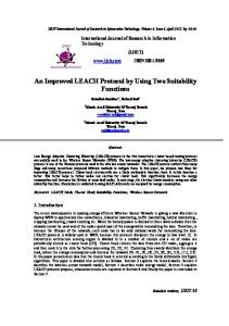
θ1
β/2
j’
C
(b)
β/2 i
j’
(c)
Figure 1. K-factor modeling
From [6], the density function of the distance between two uniform distributed points in a two dimensional area a x a is f R (r) =
4r ⋅ f0 (r) a4
(4)
with 1 2 π 2 2 a − 2ar + 2 r , for 0 ≤ r ≤ a a f 0 ( r ) = a 2 sin −1 + 2a r 2 − a 2 − a 2 r 1 2 2 −1 a − a cos r − 2 r , for a ≤ r ≤ 2a
(5)
and 0 otherwise. Let v be the velocity level of j, t be the time since last location update from j of density function ft(t)=1/ TL, 0 ≤ t ≤ TL. Since we assume that node j maintains velocity level v and movement direction δ since last update, at time t node j is randomly located on the circle ring centering j’ with radius vt. Thus, with its main beam of β degrees wide pointing to j’, node i’s probability to reach its signal to node j is described by the following scenarios. •
CASE I. r ≤ vt
As shown in Fig. 1(a), we derive that Pr{ j is under the coverage of i ' s beam | r , v, t , β , r ≤ vt} p 2θ ∠ AB = = 2π 2π
Based on the above assumptions, we consider a rectangular area of size a x a and the topological distribution of an arbitrary node is given by
=
2( β
(6)
+ θ1 ) 2 = f1 2π
By Law of Sines, in triangle ∆ij’A, there exists such relation
(2)
sin( β 2) sin(θ1 ) = vt r
When node i initiates a transmission to destination j, it forms its beam based on j’s last announced location j’. The Euclidean distance between i(xi, yi) and j’(xj’, yj’) is
r = ( xi , yi )2 + ( x j ' , y j ' )2
j’
D
B
(a)
The estimation of K involves the calculation of network topology, traffic pattern, and the underlying stochastic properties of the nodal mobility model. We make several approximations in deriving the K factor: first, we assume that nodes are stochastically located across the area of operation in accordance with a uniform distribution; second, at any moment of time, the movement direction of a mobile node is stochastically uniformly distributed from 0 to 2π; last, between two consecutive location updates, a mobile node does not change its velocity and movement direction. The latter approximation disregards certain topological constraints and the fact that nodes may turn and move within the given square area of operations. Our results will show the latter to be reasonable simplifications when the velocity level multiplied by the location update period is relatively low compared to the network size, so that the length of a movement epoch is longer than that of an update period, as is typically the case.
1 , for 0 ≤ x ≤ a , 0 ≤ y ≤ a. a2
β/2
A
i
i
B. The mobility factor K( )
f XY ( x, y ) =
A
θ1
B
θ1
r sin( β 2) vt
θ1 = sin −1
(3)
672
Authorized licensed use limited to: Univ of Calif Los Angeles. Downloaded on March 11, 2009 at 04:36 from IEEE Xplore. Restrictions apply.
(7) (8)
Plug in the value of θ1 back to (6) to get the result. •
of the product v * TL as the normalized mobility level per update period.
CASE II. vt < r ≤ vt/sin(β/2)
In Fig. 1(b), we observe that i is outside the circle, and thus one more sector needs to be included in the calculation.
IV.
Pr{ j is under the coverage of i ' s beam | r, v, t, β , vt < r ≤ = =
=
vt } sin( β / 2)
p + ∠ BC p 2(θ + θ ) ∠ AD 2 3 = 2π 2π (θ1 + β ) + (θ1 − β ) 2 2
π
2θ1
π
(9)
= f2
Note that by Law of Sines, we may derive either θ1 or (πθ1) as our solution. However, the only solution that exists, according to Fig. 1(a) and 1(b), is the one less than π/2. •
CASE III. r > vt/sin(β/2)
We investigate the dependence of system performance on the beamwidth level by observing scenarios of stationary (no mobility) entities under perfect location information update process. Notice that here mobility factor K( ) is equal to 1, denoting zero performance degradation caused by mobility induced beam aiming errors. Figure 2 depicts the system’s MAC throughput performance versus total offered load combining external arrivals and retransmissions. We find that transmitter end beamforming reduces the level of interference experienced at an intended receiver when the system operates at higher loading rates. Consequently, a higher spatial reuse factor is attained. Improved throughput performance is thus obtained as the antenna beamwidth level is reduced. We note that the use of 30-degree transmit beamwidth upgrades improvement by 400% to 500% at peak throughput, when compared to an operation with omni-directional antennas. Note that our mathematical modeling yields a very precise performance fit, when compared with simulation results.
When r > vt/sin(β/2), we see in Fig. 1(c) that the whole circle is within i’s main beam, meaning i’s signal always manages to reach node j. Pr{ j is under the coverage of vt i ' s beam | r, v, t , β , r > } sin( β / 2) = 1 = f3
(10)
While considering all three cases and integrating over r and t, we note that the integral region needs to be taken care of by three scenarios: vt ≤ vt/sin(β/2) ≤ a, vt ≤ a ≤ vt/sin(β/2), and a ≤ vt ≤ vt/sin(β/2). We hence can express the K( ) factor in the following form. K ( v, β , TL ) = ∫
TL
0
1 f k (t , v, β , TL )dt TL
PERFORMANCE EVALUATION
In this section, we evaluate the performance of the DALOHA protocol presented in this paper. For our simulations, we consider an ad hoc network consisting of 120 nodes. All the simulation results are averaged with respect to 50 different random topologies and traffic patterns. By setting TL = 10s, about 6% of a 2Mbps bandwidth capacity needs to be allocated to the control channel (for control packets that are 32 bytes long), provided that a 95% desired successful location update probability is prescribed for operating the control channel. The overhead capacity used for location update is thus relatively low. Note that on the one hand, the obvious way to reduce the imprecision induced by mobility is to reduce TL, so that location update packets are sent more frequently. In turn, the latter precision upgrade requires a higher fraction of system capacity to be allocated for location update purposes and thus not be available to accommodate user data messages. MAC layer one-hop traffic is considered to eliminate the effects of routing. Nodes are located in a 300m x 300m square area.
(11)
To evaluate the performance of the D-ALOHA scheme in
with vt vt sin( β / 2) f 2 ⋅ f R ( r )dr ∫0 f1 ⋅ f R ( r )dr + ∫vt vt + ∫0 f 3 ⋅ f R ( r )dr, when vt ≤ vt sin( β / 2) ≤ a (12) a vt f k (t , v, β , TL ) = ∫ f1 ⋅ f R ( r )dr + ∫ f 2 ⋅ f R ( r )dr 0 vt , when vt ≤ a ≤ vt sin( β / 2) a f ⋅ f ( r )dr, when vt > a ∫0 1 R
throughput (packet/slot)
2.5
bw=30 bw=60 bw=90 bw=180 omni-
2 1.5 1 0.5 0 0
The second term of equation (4) is neglected in the calculation of (12) simply due to the complexity of numerical integrals. We notice that v * t is actually one determined parameter instead of two separate parameters based on (11) and (12). This statement holds for our approximate representation
4
8 12 load (packet/slot)
16
20
Figure 2. S-G performance of selected beamwidth levels (30, 60, 90, 180, and 360 degrees). No mobility. Collision interference model assumed. Analysis and simulation data are shown in dots and lines respectively.
673
Authorized licensed use limited to: Univ of Calif Los Angeles. Downloaded on March 11, 2009 at 04:36 from IEEE Xplore. Restrictions apply.
introduce the separation property and derive comprehensive equations to model such a random access network. We characterize mathematically the effects of induced user mobility to throughput capacity. Simulation results have verified the validity of our mathematical analysis and demonstrate the high performance exhibited by our proposed D-ALOHA protocol. We show that the D-ALOHA protocol provides upgraded performance results when the beamwidth is properly selected in accordance with the underlying user mobility level.
throughput (packet/slot)
1 0.8 0.6 0.4 0.2
REFERENCES
0 0.5
1.5
2.5
3.5 4.5 5.5 load (packet/slot)
6.5
7.5
[1]
[2]
Figure 3. S-G performance of 90 degree beamwidth under mobile imperfect pointing process, collision interference model assumed. The k-th upper curve represents the performance under a velocity value that is given as v = v0 exp(ka), v0 = 2m/s and σ = 1.4.
[3]
the presence of entity mobility, we adopt a special case of the random waypoint mobility model by setting vmin = vmax, observing that the performance is not sensitive to velocity variations for our analysis. We observe the effect of velocity on network performance to follow the behavior shown in Fig. 3. In this figure, the most upper curve represents the stationary case (V=0), while the k-th upper curve represents the performance under a velocity value that is given as V=V0•exp((k-1) σ ), where V0 and σ are selected constants. The results shown in Fig. 3 validate the exact character of the separation property, noting that the performance curves representing different velocity levels track each other so that each is a constant multiple of the other. The performance of a system that employs narrower beamwidth antennas is more sensitive to mobility level variations, since narrower beamwidth beamforming operation requires higher beam pointing accuracy to take advantage of the spatial diversity of active nodal locations.
[4]
[5]
[6] [7]
[8]
[9]
The behavior of the K factor is depicted in Fig. 4, under 6 different transmitting beamwidth levels. As the operation proceeds from stationary to mild mobility scenarios, the performance is noted to drop distinctly. However, as mobility level continues to increase, the degradation gradually saturates and remains stable beyond a certain mobility level. High mobility causes high error in the beam aiming process; at high mobility levels, nodes effectively blindly transmit to arbitrary directions, instead of properly aiming in the direction of their intended receivers. Note that despite the approximations used, our analytical modeling procedure yields accurate evaluations when the results are compared with simulation data. V.
J. Ward and R. T. Compton, “Improving the performance of a slotted aloha packet radio network with an adaptive array,” IEEE Transactions on Communications, vol. 68, pp. 292-300, Feb. 1992. J. Zander, “Slotted ALOHA multihop packet radio networks with directional antennas,” Electronics Letters, vol. 26, pp. 2098-2100, Dec 1990. Harkirat Singh and Suresh Singh, “Smart-Aloha for multihop wireless networks,” J. Mobile Networks (MONET) Special Issue on "WLAN Optimization at the MAC and Network Levels," 2004. M. Takai, J. Martin, and R. Bagrodia. Directional virtual carrier sensing for directional antennas in mobile ad hoc networks. In Proc. ACM International Symposium on Mo-bile Ad Hoc Networking and Computing (MOBIHOC), Lausanne, Switzerland, Jun. 9-11 2002. R. R. Choudhury, X. Yang, R. Ramanathan, and N. Vaidya, “Using directional antennas for medium access control in ad hoc networks,” ACM MOBICOM, Jun. 2002.. B. Ghosh, “Random distances within a rectangle and between two rectangles,” Bull. Calcutta Math. Soc., vol. 43, pp. 17–24, 1951. A. Nasipuri, S. Ye, J. You, and R. E. Hiromoto, “A MAC protocol for mobile ad hoc networks using directional antennas,” In Proc. of WCNC2000. T. Ueda, S. Tanaka, D. Saha, S. Roy and S. Bandyopadhyay, “LocationAware Power-Efficient Directional MAC Protocol in Ad Hoc Networks Using Directional Antenna,” IEICE TRANS. COMMUN., VOL.E88–B, NO.3 MARCH 2005 J. Hsu and I. Rubin, "Performance analysis of directional random access scheme for multiple access mobile ad-hoc wireless networks," sumbitted to IEEE MILCOM 2005.
1.2
30 degree 60 degree 90 degree 180 degree
K-factor
1 0.8 0.6 0.4 0.2 0 0
CONCLUSIONS
10
20 30 40 mobility level v(m/s)
50
60
Figure 4. K-factor – mobility level of selected beamwidths, collision interference model assumed. Analysis and simulation data are shown in lines and dots respectively.
This paper presents a directional slotted Aloha based MAC protocol, identified as D-ALOHA, for the use of transmitterbased directional beamforming in mobile ad hoc networks. We
674
Authorized licensed use limited to: Univ of Calif Los Angeles. Downloaded on March 11, 2009 at 04:36 from IEEE Xplore. Restrictions apply.