Impact of Fiber Chromatic Dispersion on DS-OCDMA System Ye Zhang, Yitang Dai, Shizhong Xie Tsinghua University. Room 11-112, East Main Building, Tsinghua Univ., Beijing, China.
[email protected] Abstract A criterion, fmaxLmaxD=102, is proposed to judge the maximum fiber access distance, within which chromatic dispersion can be neglected. And it is verified by a 2×2 DS-OCDMA system at 127-chip 320-Gchip/s. Key words OCDMA; fiber chromatic dispersion; PIN receiver Introduction Chromatic dispersion in fiber communication systems has long been explored. The criterion, B2LD=105, seems that dispersion would not be an important mechanism in short-distance fiber communication systems intended for deployment in local area and access networks. However, optical code division multiple access (OCDMA) system generally works at 320-Gchip/s or higher. And here, the criterion above is not apt to depict the impact of chromatic dispersion, which degrades system performance due to the spreading and overlapping of chip signals and the reducing of signal power at PIN receivers. pulse AM source 127 chips ~ 2 ps 5 GHz 320 Gchip/s signal encoders clock sequence
decoders
PIN Receiver
Fig. 1 block diagram of a 2×2 OCDMA system According to Fig. 1, our OCDMA system consists of a ultra-short pulse generator, a PIN receiver, phaseencoded FBG en/decoders, and so forth. The impact of chromatic dispersion in this phase-encoded, asynchronous and coherent, direct sequence OCDMA (DS-OCDMA) system is demonstrated in the following part. The output signal at receiver is estimated by a proposed criterion, and verified experimentally by measuring signal to noise ratio (SNR) and power gain of dispersion compensation in a 2×2 OCDMA system before the last conclusion part. Chromatic Dispersion in Fiber The pulse generator produces a Gaussian pulse
gin (t ) = e − t
2
/ 2T0 2
(1)
where T0 represents the pulse temporal width, which is defined at 1/e of the peak power. After passing through a pair of en/decoder, the optical signal g(t) is given by
g (t ) =
T0 T2
2 N −1
∑C e k =1
2
k
t k2 / 2T22 2
(2)
where tk=t–kTchip, T2=(T0 +2p2Tchip )1/2. Tchip is the temporal interval between contiguous code chips, and p is defined as the duty rate of temporal code width. N is the code length, Ck is either autocorrelation coefficient of code sequence when signal passes a matched decoder or cross-correlation coefficient of
that when signal encounters a mismatched one. Note that T2>T0, because the high frequency of initial Gaussian pulse is filtered out by en/decoder. For instance, the initial optical pulse FWHM width in our experiment is about 2 ps, and the recovered pulse FWHM width is around 3 ps. The signal g(t) could be divided into many small Gaussian pulses along the time domain. After transmitting a certain distance with chromatic dispersion, every small Gaussian pulse has its corresponding spread. Each of these dispersed small Gaussian pulses can be simplified to
g k (t ) =
Ak T + jβ 2 L 2 2
e − t k / 2 (T2 + jβ 2 L ) 2
2
(3)
where β2=-λ2D/(2πc), Ak is the amplitude coefficient in (2), Ak = Ck (T0 / T2). And L is fiber length, D is fiber chromatic dispersion coefficient. Comparing to AN, coefficient Ak (k≠N) keeps small. So there are a bunch of small Gaussian pulses in fiber, and they have mutual overlapping and spreading effects. Furthermore, there will be inter-symbol interference (ISI) and multi-access interference (MAI), which result in the degradation of OCDMA performance [1]. But if we focus on the performance comparison, the ISI, MAI and such small Gaussian pulses could be considered as a fixed level interference to the received signal [2]. Typically, these small Gaussian pulses are randomly deployed along the time domain. They have respective intensities and phases, and the probability distribution function which reaches a Gaussian distribution [3]. While chromatic dispersion acts on them, these pulses spread and overlap each other. But the optical power of the encoded signal does not disperse apparently along the time domain, since these pulses will intermeddle in neighboring pulses, and hand their power on each other. So, the variance of peak power of small Gaussian pulses and ISI, MAI performances due to chromatic dispersion is among a small range. Moreover, the noise power N0 includes photodetector shot noise power and receiver thermal power. None of these noises has an optical power comparable to that of ISI or MAI in OCDMA system. So SNR gain due to dispersion compensation almost equals its corresponding gk(t)(k=N) signal gain. PIN Receiver Mechanism Theoretically, PIN can be composed of a square law
receive device and a low pass filter. In PIN receiver, pulses with equal optical power but different Gaussian forms generate different respondent electrical signals, because PIN converts the optical stream into an electrical time-varying signal under the square law. In fact, we can get the electrical frequency curves at different dispersed pulse FWHM width in Fig. 2 through the integral of squared peak signal. +∞
F (ω ) = ∫ g −∞
2 k=N
(t )e
− jωt
dt = π A T e 2 N 2
−
2 Tout ω2 4
⎛ 1 − ex ⎞ ⎛ f (0) ⎞ ⎟⎟ ⎟⎟ = −10 log⎜⎜ Elog = 20 log⎜⎜ T ⎝ f (0) ⎠ ⎝ x ⎠
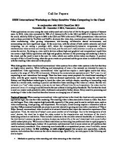
where compensated electrical voltage signal fT(0) is obtained by (5) at Tout=T2. Power gain due to dispersion compensation, Elog, at different receiver bandwidth is estimated by (7) and experimentally measured in Fig. 3, respectively. 20
(4)
Tout =T22+(β2L/T2)2.
where When the carrier wave is filtered out, the zero frequency of the electrical signal presents the received optical power. Dispersion dose not change the optical power, so F(0) is dependent of chromatic dispersion parameters.
Power (dBm)
10G 30G
65G
3 ps 10 ps 24 ps 95 ps 475 ps
-90
-95
-100
0
50
100
150
200
250
Frequency (GHz) Fig. 2 electrical frequency of dispersed pulse width Note that the highest electrical frequency of dispersed signal must be smaller than that of compensated one. Thus compensated signal always gives a larger electrical response than dispersed signal does. But received electrical frequency range must be limited by maximum electrical bandwidth fmax. Then, the peak of electrical voltage signal at oscilloscope is given by
f (0) =
1 2π
∫
ω max
0
F (ω )dω =
12 AN2 T2 ( 1 − e − x ) (5) Tout
where ωmax=2πfmax, x = (Toutπfmax)2. In the case of x«1, we can get an approximation that (1-e-x)=x. Then, f(0)=A2T2πfmax is independent of chromatic dispersion. Moreover if L is larger than tens of meters, Tout≈β2L/T2. So we obtain the criterion that fmax[GHz]Lmax[km]D[ps/km/nm]=102 (6) where Lmax is the maximum fiber length, within which dispersion in OCDMA system can be neglected. Therefore, whether we should consider the dispersion or not, is not only depended on the transmission distance L and fiber dispersion coefficient D, but also depended on the bandwidth of the PIN receiver fmax. Actually, fmax is partially depended on the bit rate, since it must be larger than half of the bit rate in order to distinguish two contiguous signals. Larger receiver bandwidth will upraise the receiver performance and worsen the dispersion effect, simultaneously. While fmaxLD > 102, the power gain due to dispersion compensation, Elog, is then given by
Power Gain (dB)
2
-85
(7)
15
10
10 GHz experiment 10 GHz estimation 30 GHz experiment 30 GHz estimation
5
0
0
2
4
6
8
10
SMF-28 Access Distance (km) Fig. 3 power gain by dispersion compensation The difference between the two pairs of curves shows that chromatic dispersion criterion is in accord with practical experiment when fmaxLD keeps in a few tens. As fmaxLD increases, the curves gradually drift apart, because the dispersion is so large that severe mutual interference deviates the bunch of signals from their initial Gaussian form. In addition, if we choose optical threshold devices or other photodetectors instead of PIN, we can also make the similar analysis and obtain an analogical result. Conclusions The performance of fiber chromatic dispersion and its corresponding compensation in a DS-OCDMA system is discussed in this paper. A criterion, fmaxLmaxD=102, is proposed as a condition to judge whether dispersion compensation is needed or not. And when fiber length is longer than Lmax, the power gain of dispersion compensation is estimated by (7) and verified in Fig. 3. In the case of SMF-28 with D=16 ps/km/nm, and dispersion-shifted fiber (DSF) with D=3 ps/km/nm at receiver bandwidth fmax=10 GHz, the maximum fiber access distance with neglectable dispersion is about 0.6 km and 3.3 km, respectively. References [1] X. Wang et al, “Impairments and limitation of intersymbol-interference and beat noise in data-rate flexible OCDMA with SSFBG en/decoder”, Opt. Express, 13(2005), pp. 10 469–10 474 [2] X. Wang et al, “Coherent OCDMA System Using DPSK Data Format With Balanced Detection”, IEEE Photon. Technol. Lett., 18(2006), pp. 826-828 [3] W. Ma et al, “Performance analysis on phaseencoded OCDMA communication system”, J. Lightwave Technol., vol. 20 (2002), pp. 769–775