Proceeding of the 20 l3 RSI/ISM International Conference on Robotics and Mechatronics February 13-15,2013,Tehran,Iran
A Positive Tensions PID Controller for a Planar Cable Robot: An Experimental Study Mohammad A. Khosravi*, Hamid D. Taghirad* and Reza Oftadeht * Advanced Robotics and Automated Systems (ARAS),Industrial Control Center of Excellence (ICCE), Faculty of Electrical and Computer Engineering, KN. Toosi University of Technology,Tehran,Iran. Email: {Makh,Taghirad}@ieee.org t Intelligent Hydraulics and Automation Department (lHA),Tampere University of Technology,Finland. Email:
[email protected]
Abstract-In this paper design and control of planar cable driven parallel robots are studied in an experimental prospective. Since in this class of manipulators, cable tensionability conditions must be met, feedback control of such robots becomes more challenging than for conventional robots. To meet these condi tions, internal force control structure is introduced and used in addition to a PID control scheme to ensure that all cables remain in tension. A robust PID controller is proposed for partial knowledge of the robot, to keep the tracking errors bounded. Finally, the effectiveness of the proposed control algorithm is examined through experiments on K.N. Toosi planar cable-driven robot and it is shown that the proposed control structure is able to provide suitable performance in practice.
I.
I NT RO DUCTION
Although the robots are extensively used in industries, their applications in long-reach robotics is limited and still is in infancy. Conventional robots with serial or parallel structure are impractical for such applications due to their limited workspace. for these reasons,cable-driven robots have received more attention in the past two decades. Cable-driven robots are a special class of parallel robots in which cables replace rigid links in the robot structure. In a cable-driven robot the end-effector is connected to the base by a number of active cables and by controlling the cables lengths,the pose of the end-effector is shifted toward the desired position and orientation. Cable-driven robots possess some useful properties such as large workspace capability,transportability and ease of assembly/disassembly,reconfigurability and economical struc ture and maintenance [1]. As a result,cable-driven robots are exceptionally suitable for many applications such as,handling of heavy materials [2], high speed manipulation [3], [4], cleanup of disaster areas [5],very large workspace applications [6], [7],and interaction in hazardous environment [8]. However, replacing rigid links by cables, introduces new challenges in the study of cable-driven robots which are quite different from that of conventional robots. Unlike the rigid links, cables can only apply tensile forces. Due to this physical limitation, well-known control theories can not be used directly for cable-driven robots and they must be modified such that they can provide positive tension for the cables. In comparison with the large amount of articles published on the control of conventional robots, relatively less has been pub lished on the control of cable-driven robots. With assumption
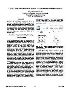
Fig. 1.
K.N. Toosi planar cable-driven robot.
of massless rigid string model for the cables,many of control schemes which have been used for conventional robots,may be adapted for cable robots. PD control in companion with gravity and internal forces in the cable-length coordinates [3], PD control with gravity in task space coordinates [9], and Inverse Dynamics Control (IDC) [9], [10], [11], are some control algorithms which are used in control of cable-driven robots. The goal of this paper is to practically develop a control algorithm based on popular PID for position control of KN. Toosi planar cable-driven robot (Fig. (1» and investigate experimental performance of such a control structure. In order to ensure that all the cables are in tension for all maneuvers in their workspace,internal force structure control is used in addition to the proposed control law. Next,the implementation issues are discussed and finally,experimental results are given to show the effectiveness of the proposed control algorithm in practice. II.
SY S T E M KINE M ATICS AN D DY N A MICS
KN. Toosi planar cable-driven robot consists of an end effector that is connected by four cables to the base platform
978-1-4673-5811-8113/$31.00 © 2013 IEEE 325
224=
Li
A;
(b)
(a) Fig. 3.
(a) Kinematic configuration of mechanism (b): Vector definitions
trated in Fig. (3-b),the manipulator Jacobian matrix J is, Fig. 2.
The schematics of K.N. Toosi planar cable-dricen robot.
J= as shown in Fig. (2). As it is shown in Fig. (2), Ai denote the fixed base points of the cables, Bi denote connection points of the cables on the end-effector, Ii denote the cable lengths, and (Xi denote the cable angles. The position of the end-effector center of mass P, is denoted by P = [xp, yp], and the orientation of the manipulator end-effector is denoted by ¢ with respect to the fixed coordinate frame. Hence, the manipulator posses three degrees of freedom x = [xp, YP, ¢], with one degree of actuator redundancy. A.
SIx S2x S3x S4x
Sly S2y S3y S4y
ElxSly - ElySlx E2xS2y - E2yS2x E3xS3y - E3yS3x E4xS4y - E4yS4x
B.
(i = 1,2,3,4),
Using massless rigid string model for the cable,the equa tions of motion for the planar manipulator can be written in the following form,
in which,x = [xp, YP, o m
o
where m is the the end-effector Jacobian matrix acceleration and
With some manipulation we can show that [12],
Furthermore, for the geometry of the manipulator as illus-
¢]
i1
72:0
(2)
and and
(3)
mass and Iz is the moment of inertia of about its center of mass. J denotes the of the manipulator, 9 is the gravitational 7 denotes the vector of cables tension, i.e., 7= [Tl' T2, T3, T4]. It should be noted that the above dynamic model is valid only for T 2:0 and as soon as the cables become slack,the structure of the robot collapses. All geometrical and mechanical parameters of the cable-driven robot are given in tables (1),(11). III.
can
(1)
Dynamic Model
Mx+G=-JT7
For kinematic analysis,as it is shown in Fig. (3-a),a fixed frame 0 : xy is attached to the fixed base at point 0, the center of the base point circle which passes through Ai' Moreover, another moving coordinate frame P : UV is located on the end-effector at its center of mass P. Assume that the point Ai lies at the radial distance of RA from point 0, and the point Bi lies at the radial distance of RB from point P in the xy plane,when the manipulator is at central location. For inverse kinematics analysis,it is assumed that the position and orientation of the end-effector x = [xp, YP, ¢]T are given and the problem is to find the lengths variable of the manipulator L = [h, 12, l3, 14]T. Let's define the instantaneous orientation angle of Bis:
1
in which, the subscripts x, and y denote the corresponding components of the Si and Ei vectors as shown in Fig. (3-b). Note that the Jacobian matrix J is a non-square 4 x 3 matrix, since the manipulator is redundantly actuated.
Kinematics and Jacobian
The loop closure equation for each cable be written as,
r
P RO POSE D CONT RO L LER
As mentioned earlier, for the cable-driven robots control algorithms must be designed in such a way that all cables remain in tension during the motion of the end-effector in the whole workspace. In this section, we propose a practical control scheme based on popular PID. This algorithm uses internal force concept to ensure that all cables remain in tension. Furthermore, In design procedure of the controller it is assumed that all dynamic terms such as m and Iz are uncertain and we have only some information about their
326
T AB LE I POSITION OF THE CABLE ATTACHMENT POINTS Fixed Ai'S (m) Al (-1.12, +1.05) A2 (+1.12, + 1.05) A3 (-1.12, -1.05) A4 (+ 1.12, -1.05)
Moving Bi'S Bl (-0.155, B2 (+0.155, B3 (-0.155, B4 (+0.155,
T AB LE II INERTI AL PARAME TER OF THE PLANAR CABLE-DRIVEN ROBOT Parameter
(m) 0) 0) 0) 0)
End-effector mass End-effector inertia Gear ratio Gravity Acceleration Drum radius
bounds. Control gains of PID are tuned base on these bounds to satisfy some stability conditions. Recall dynamic model of the planar robot (2), in presence of uncertainties in all dynamical terms, it can be simply shown that if the end effector mass is 2.5 kg with a variation of 0. 5 kg payload then,
m:S; II M(x)11 :s; m , m IIG(x)11 :s; 30
= 3 , m = 0.08
in which,
iJ
(4)
x
and
T=7'+Q
(5)
Here,7' is the minimum solution of (4) derived by using the pseudo-inverse of JT and is given by
Q
50 9.8 mls2 3.5 cm
= Ay+B6A
t K [ ve+Kpe+KJ fo e(S)dS]
(6)
[ -} 'KI B� [ J-, 1
(11)
(7)
Q can be written in the following form,
(12)
Khosravi and Taghirad in [13] have elaborated uniformly ultimately bounded (UUB) stability of a general cable-driven robot when control gains of PID are selected from a suit able feasible set. The proof of UUB stability is based on Lyapunov stability analysis for the uncertain system. For our implemented planar cable-driven robot,the controller gains are selected as 1000013, 300013, 60013 in the feasible stability region of the system considering the modeling uncertainty bounds. In this paper we leave the details of the proof, and verify the performance of the closed-loop system through experiments.
Kp =
IV.
spans the null space of JT which satisfies
Kv =
KJ =
EX PERI MENT A L SETU P
In this section some practical issues in design and imple mentation of K.N. Toosi planar cable-driven robot are investi gated. It should be noted that mechanical design and the choice
Furthermore,
(8) where,N(JT) is the null space or kenel of matrix JT which in this case is a 4 x 1 vector and c is an arbitrary scalar. can be physically interpreted as internal forces. It means that this term does not contribute into the motion of the end-effector and only provides positive tension in the cables. In other words,input constraint 0 is met using internal forces
Q
T;:::
7'+Q;:::O
(10)
6A = G(x) + MXd
Since Jacobian matrix of the manipulator is a non-square 4 x 3 matrix, (4) is an underdetermined system of equations and if JTJ is invertible it has many solutions. In this case, the general solution of (4) is,
and,
Iz N g
A�
y = [J� eT(s)dseT eT(
7'=-J(JTJ)-l
2.5 ± 0.5 Kg 0.1 ± 0.02 Kg.m2
in which,
{ �== � Kp Kvl x [
Value
m
at all times,positive internal forces can be produced such that the cables are in tension. Implement the control law T in (2) to get the following relations for the closed loop system:
Now choose a controller for the system based on a PID by:
-JTT=Kve+Kpe+KJ fote(S)dS=KY
Symbol
(9)
with this notation,the proposed control scheme can be imple mented according to Fig. (4). In this paper we assume that
327
Fig. 4.
Internal force control structure.
PC (Host)
PC (Target) [QNXI
[Windows] {R'·Lab}
PCt Cards
IAdvantech)
Fig. 6.
Fig. 5.
The system of cable winch
of electrical and mechanical components may significantly affect the overall performance of the manipulator. Thus,these subjects are of particular importance and should be consider in the design and implementation procedure of the manipulator. A.
Mechanical Structure
The base frame of the robot is implemented by extruded aluminum profile so that the vibrations are damped efficiently. These extruded profiles are common in many industrial assem blies. Moreover,four custom made systems of cable winches are placed on the base frame as cable actuators. The system of cable winch consists of an AC servo motor with a 1:50 gearbox which is attached to a drum. A special design is used in the cable winches by which the base attachment points of the robot are kept fixed. As it is shown in Fig. (5),this is accomplished by moving the drum along its axis with a pitch equal to the cable width. Furthermore,two touching ball bearings are used to guide the cable toward the end-effector. Cable selection is another important issue in cable-driven robots. In this application, cables should be light and shall resist high loads and tensions. Furthermore, selected cable should be sufficiently stiff to have less elongation due to applied loads. For these reasons,polyethylene cable with tissue pattern 1 x 7 has been selected for K.N. Toosi planar cable robot [14]. B.
Control System Structure
The block diagram of the control system setup is shown in Fig. (6). The host computer serves as the user interface and enables the user to edit and modify models. Target is a real time processing unit which uses QNX operating system and performs real time execution of the model simulation and real time communication with 1I0s. RT-LAB software works in conjunction with Matlab and Simulink to define models in real time environment. RT-LAB is designed to automate the execution of simulations for models made with Simulink, in a real time multiprocessing environment [15]. A number of PCI input/output boards were integrated with the RT-LAB and Simulink to create a real time control system. To have a desirable performance in position and orientation tracking, servo drives should accurately provide the required tensions in the cables according to the proposed control algorithm. In other words,the servo drives shall be ideal force
Servo Drives
Control system setup
generators when seen by the proposed control algorithm. This is due to the fact, that in the procedure of control design it is assumed that the cables are rigid, but in practice this is not completely true. Based on this fact, cascade control scheme is implemented in the experiments to provide ideal force sources. The cascade control strategy uses two control loops, namely the outer loop and the inner loop as shown in Fig. (7). The main goal of the outer loop, which consists of the proposed PID control, is to control the position and orientation of the end-effector. Inputs of this loop are the position and orientation errors and its outputs are required tensions for the inner loop. In the inner loop, the desired tensions are compared to actual tensions measured by the load cells located near the end-effector attachment points. TLL500 from Transducer Techniques is used as load cell in our experiments. Moreover,internal force control structure is used to ensure us that all the cables remain in tension. The proposed controller is implemented using Matlab real-time workshop and RT-LAB software. The equations of forward kinematics is solved using CFSQpl routine [16] implemented as an s function in Simulink to derive Cartesian position x (x, y, ¢) from encoders information L at real time. Moreover, this routine is used to find required internal forces from (7). =
V.
EX PERI MENT A L RESU LTS
In order to show the effectiveness of the proposed control algorithm,several experiments are performed. In the first set of experiments, two disjointed linear motions in translation and rotation are considered. In these experiments, step input as a set point is applied to the robot. Step function has this feature that it can excite almost all dynamics of the system. As a result, investigation of the step response can be a suitable measure in performance evaluation of the robot. Furthermore,a more challenging circular profile is considered in the next experiment,to track a circular path of 0.2m about the central position. For the first experiment, suppose that
328
I C code for Feasible Sequential Quadratic Programming
PIO Control
Internal
Planar
Force
Cable
Control
x
Fig. 7.
Cascade control block diagram
L
,�;r 0.03
••
0.5
0
1.5
_'··I'·�'O ' ••• j 2.5 time (ms)
4.5
3.5
':bb �i �; � r'-' ·�r� ·i i i� j
-c:-' --' :-----'-----4L L -----'---' ...L -L------- 5 '----� .5-----5-' , .5:----'------,: 3.5 O .5 0 2.5 time (ms) x 104
5
time (ms)
,�� � -.�-.,-. • j 0.5
o
1.5
2.5 time (ms)
3.5
4.5
5
Fig. 8. Implementation results showing the actual and desired position and orientation of the end-effector for Xd = [0,0.25, ojT Tension 1
time (ms)
Fig. 10. Implementation results showing the actual and desired position and orientation of the end-effector for Xd = [0,0,1r/6jT
Tension 2
Tension 1
Tension 2
z
2 3 time (ms)
2 3 time (ms)
Tension 3
Tension 4
z
Tension 3
Tension 4
z
z
2 3 time (ms)
Fig. 9.
2 3 time (ms)
Implementation results showing the cables tension for
[0,0.25,0]T
Xd
=
the initial posItIOn of the end-effector is x [0,0,0lT in SI units and the desired end-effector position and orientation is Xd [0,0.25,0lT. The results of implementation using proposed PID control (4) in companion with the internal force control structure,are given in Fig. (8). As it is seen in this figure,position and orientation outputs suitably track the desired trajectories and the steady state errors are very small, while as it is shown in Fig. (9) all cables remain in tension for the whole maneuver. The prescribed uniformly ultimately =
=
Fig. 11.
Implementation results showing the cables tension for
[0,0,1r/6jT
Xd
=
bounded tracking error for the control structure is verified in all three directions in this experiment. In the next experiment,suppose that the desired orientation of the end-effector is Xd [0,0,1f /6 radV, while the same controller gains are considered. The results of this experiment are given in Fig. (10). As it is observed,tracking performance is very suitable and the position errors in x and y directions are small and in order of 10-3. Furthermore, as it is shown in Fig. (11),all cables are in tension.
329
=
0.25
prospective. To develop the idea, kinematics and dynamics of the planar cable-driven robot are firstly studied. According to unique property of the cables that can only apply tensile forces, and in order to ensure that all the cables are in tension at all times, internal force control structure is used with proposed PID algorithm. A robust PID controller is proposed to overcome partial knowledge of the robot,and to keep the tracking errors bounded. Next,important aspects in implementation of the robot are discussed and control structure of the robot is proposed using cascade control concept. Finally, several experiments on K.N. Toosi planar cable-driven robot are performed. The results show suitable tracking capability of the robot with different desired trajectories, while all the cables remain in tension at all times.
0.2
0.15
0.1
0.05
>-
-0.05
-0.1
-0.15
-0.2
REFERENCES [1]
-0.2
-0.15
-0.1
-0.05
o X
0.05
0.1
0.15
0.2
0.25
Fig. 12. Implementation results showing circular trajectory generation by the end-effector Orientation 'P
M. A. Khosravi and H. D. Taghirad, Dynamic Analysis and Control of Cable Driven Robots with Elastic Cables. Trans. Can. Soc. Mech. Eng., Vol. 35, No. 4, pp. 543-557, 2011. [2] R. Bostelman, J. Albus, N. Dagalakis, and A. Jacoff, Applications of the NIST Robocrane. Proceedings of the 5th International Symposium on Robotics and Manufacturing, 1994, pp. 403-410. [3] S. Kawamura, H. Kino, and C. Won, High-speed manipulation by using parallel wire-driven robots. Robotica, Vol. 18, No. 3, pp. 13-21, 2000. [4] K. Maeda, S. Tadokoro, T. Takamori, M. Hiller, and R. Verhoeven, On design of a redundant wire-driven parallel robot WARP manipu lator. Proceedings of IEEE International Conference on Robotics and
time (ms)
Fig. 13. Implementation results showing the rotation trajectory generation
during circular
For the circular profile, the end-effector is commanded to track a circle with radius of 0.2 meter in 10 seconds, while attempting to maintain zero orientation ¢ 0, at all times. The reference Cartesian positions for this experiment are x 0.2cos(0.27ft) and y 0.2sin(0.27ft). Figures (12) and (13) show the reference and actual circle and deviation of ¢ from its zero desired value. It is shown that the simple PID control scheme is capable to stabilize the system and performs such maneuver,while the absolute positioning errors are relatively small. As it is seen in Fig. (13),orientation error in this test is very small and in order of 10-3 =
=
=
V I.
CONC LUSIONS
This paper addresses the issues of dynamic analysis and control of a planar cable-driven robot in an experimental
330
Automation, 1999, pp. 895-900. [5] R. Roberts, T. Graham, and T. Lippitt, On the Inverse Kinematics, Statics, and Fault Tolerance of Cable-Suspended Robots. Journal of Robotic Systems, Vol. 15, No. 10, pp. 649-661, 1998. [6] L. Cone, Skycam: An aerial robotic camera system. Byte, vol. 10, pp. 122132, 1985. [7] H. D. Taghirad and M. Nahon, Kinematic Analysis of A Macro-Micro Redundantly Actuated Parallel Manipulator. Advanced Robotics, Vol. 22, No. 6-7, pp. 657-87, 2008. [8] A. Riechel, P. Bosscher, H. Lipkin, and I. Ebert-Uphoff, Concept paper: Cable-driven robots for use in hazardous environments. Proceedings of 10th Int. Topical Meet. Robot Remote Syst. Hazardous Environ., Gainesville, 2004, pp. 310-317. [9] A. Alp and S. Agrawal, Cable Suspended Robots: Feedback Controllers with Positive Inputs. Proceedings of the American Control Conference, 2002, pp. 815-820. [10] R. L. Williams, P. Gallina, and 1. Vadia, Planar Translational Cable Direct Driven Robots., Journal of Robotic Systems, Vol. 20, No. 3, pp. 107-120, 2003. [11] S.R. O h and S. Agrawal, Cable Suspended P lanar Robots with Re dundant Cables: Controllers with Positive Tensions., IEEE Trans. on Robotics, Vol. 21, No. 3, pp. 457-465, 2005. [12] Y. Babazedeh, H. D. Taghirad, and M. M. Aref, Dynamics analysis of a redundant parallel manipulator driven by elastic cables. Proceedings of the IEEE 10th International Conference on Control, Automation, Robotics and Vision, 2008, pp. 536-542. [13] M. A. Khosravi and H. D. Taghirad, Robust PID Control of Fully Constrained Cable Driven Parallel Robots. submitted to Mechatronics, 2012. [14] Plasma Cables, http://www.cortlandcompany.com. 2012. [15] RT-LAB version 8 User Guide., O pal-RT Company, 2005. [16] c. Lawrence, J. L. Zhou, and A. L. Tits, User's Guide for CFSQP Version 2.0: A C Code for Solving Constrained Nonlinear Optimization Problems, Generating Iterates Satisfying All Inequality Constraints.,
Technical Report, Institute for systems Research, U niversity of Mary land, TR-94-16, 1994.