Can. Soc. Forensic Sci. J. Vol. 42. No 3 (2009) pp. 200–209
CASE REPORT UTILIZING GROUND PENETRATING RADAR FOR THE LOCATION OF A POTENTIAL HUMAN BURIAL UNDER CONCRETE MICHAEL S. BILLINGER1
ABSTRACT Cold case files present investigators with significant challenges in terms of the location and preservation of evidence, particularly when investigating the disappearances of missing persons who are likely to have been victims of homicide. This report details such challenges as experienced during a recent investigation conducted by the Edmonton Police Service in Alberta, Canada. The author acted as a consulting forensic anthropologist to assist in locating and recovering human remains that were presumed to have been buried under a concrete floor in the basement of a residential dwelling. Ground Penetrating Radar (GPR) technology was utilized in order to determine the location of the potential burial under the concrete. Despite positive results obtained through the GPR analysis, the excavation was met with negative results. This paper, therefore, cautions about false positive results when using GPR technology for locating possible burials under concrete.
RÉSUMÉ Les dossiers de causes non résolues représentent de grands défis pour les enquêteurs en terme de lieu et de préservation d'éléments de preuve, particulièrement lors d'enquêtes de personnes portées disparues qui ont probablement été victimes d'homicides. Ce rapport raconte certains défis qui ont été rencontrés lors d'une récente enquête menée par la Edmonton Police Service en Alberta, Canada. L'auteur a agi en tant que conseiller anthropologue en sciences judiciaires pour assister à dénicher des dépouilles mortelles qui ont été supposément enterrées sous un plancher de béton dans un sous-sol d'un logement résidentiel. La technologie de radar par pénétration du sol (RPS) a été utilisée afin de déterminer l'endroit de l'enterrement potentiel sous le béton. Malgré des résultats positifs par analyses de RPS, l'excavation s'est avérée sans succès. Cet article fait donc une mise en garde de résultats positifs lorsque la technologie RPS est utilisée pour retrouver des enterrements potentiels sous le béton.
INTRODUCTION In early 2008, the Edmonton Police Service (EPS) Homicide Section was provided with information from a potential witness relating to the disappearance and assumed homicide of a young female, who was last seen in 1983. The information provided was that an individual, who may have known the family of the missing female, had conducted repairs to the concrete floor in the basement of his home at approximately the same time as the 1.
Edmonton Police Service, 9620 – 103A Avenue, Edmonton, Alberta, Canada, T5H 0H7. Phone: 780-421-3306. Email:
[email protected]
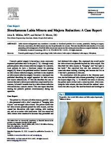
female’s disappearance. It was believed that the missing female’s body had been buried under the concrete floor. The lead homicide investigator consulted with members of the EPS Crimes Scenes Investigation Unit, who attended the residence in question and conducted a preliminary examination of the concrete floor in the basement. It was immediately obvious that much of the floor was not original, but that a large area surrounding a drain near the centre of the floor had been patched with concrete of a lesser quality. The investigators deemed that further investigation was necessary in order to determine the validity of the potential witness’s information. In May 2008, the author was consulted by a member of the Crime Scene Investigation Unit, who had knowledge of the author’s background in forensic anthropology and archaeology, as to possible location and excavation techniques. The use of geophysical technology such as Ground Penetrating Radar (GPR) for locating archaeological sites was suggested as a possible method for locating buried human remains. GPR is a non-intrusive method for detecting buried objects or substances in a nonmetallic material through the use of radio waves. GPR systems work by emitting a short electromagnetic pulse in the ground through a wide-band antenna. Reflections from the ground are then measured to form a vector. An image is built by displaying these vectors side by side with the displacement of the antenna. By moving the antenna along a line and taking regularly spaced acquisitions, it is possible to construct an image representing a vertical slice of the ground (1). The depth and size of subsurface features can be estimated with a reasonable degree of accuracy (2). A preliminary review was conducted relating to the use of GPR in a forensic context. Several publications have documented the successful utilization of GPR for locating burials in the context of homicide investigations (2-9). One particular advantage of utilizing GPR technology is that it can be used to search for burials under concrete or asphalt without having to excavate or otherwise damage the surface (2). Of specific interest was a report detailing the use of GPR to locate the remains of an individual who had been buried beneath a concrete pool deck for 28 years (9). A local company (Maverick Inspection Ltd.) was contracted to provide a GPR survey in order to determine whether a burial could be detected. CASE REPORT The GPR survey was conducted in June 2008, utilizing a MALÅ Geoscience Inc. CX-11® GPR unit connected to a “digital video logger”, which captures and displays data that can be analyzed in real time and then transferred to a laptop or PC for data interpretation. The floor under investigation was located in a room in the basement of the home. The room contained a washing machine, clothes dryer, shelving units, a furnace, and a hot water tank. Without disturbing the contents of the room, a series of X-Y axis grids were drawn on the exposed concrete floor using a back felt-tipped marker. A total of 5 grids were drawn (Figure 1)2, encompassing the majority of the concrete patch that had been previously identified.
2.
Grids 1, 2, 4, 5 measured 24” × 24” (61 cm2). Grid 2 measured 36” × 36” (91.4 cm2). Data was gathered to a depth of 25.6” (65 cm) from all grids.
201
5
4
3
2
Figure 1.
1
Configuration of grids used during GPR analysis as marked on concrete floor (Not to scale).
Each grid was examined briefly on-site, with real time interpretation of the images demonstrating the existence of significant anomalies in Grid 4 at a depth of 18.1 cm (7.12 inches) (Figure 2). The data for each grid was then reanalyzed using the planview mapping functions built into the CX-11. Some anomalies were present, as were inconsistencies within the dielectric constant throughout the grids. These inconsistencies were generally within the “normal” range for concrete inspection, though, based on the technician’s experience, there appeared to be signs of voiding or density loss under the concrete floor. Some areas appeared to contain strong void signatures. Grid 4 contained a very strong reflector (Figure 3), which extended out of the grid pattern to the south and continued into Grid 5. Overall, the GPR technician concluded that the readings in the southernmost portion of the examined area were not typical for a slab-on-grade foundation. It appeared to contain voiding and other points of interest. As a result, the investigators decided that it would be necessary to excavate the concrete floor and a search warrant was obtained in order to conduct the forensic examination. A company specializing in concrete flooring was contracted to cut the floor for removal. 202
Figure 2.
Screen capture of anomaly present in Grid 4 during real time GPR interpretation.
In July 2008, the lead homicide investigator, accompanied by two members of the Crime Scene Investigation Unit and the author, attended the home to execute the search warrant and commence the excavation. The grids that were drawn on the concrete floor during the GPR analysis were still visible and served as guidelines for the establishment of a larger grid system. All appliances were removed from the room and the remaining floor space was measured. It was determined that there was sufficient space to allow for a grid of four 1.0 m × 1.0 m squares (4.0 m2) to be drawn on the floor. This larger grid encompassed the entire area of patched concrete as well as the majority of accessible floor space. Making allowances for the exposed drainpipe on the south wall and the natural gas inlet for the clothes dryer on the west wall, a datum point3 was established in the southwest corner of the room, 20 cm from the south wall and 15 cm from the west wall. Once the 4.0 m2 grid was drawn on the floor, it was decided to extend the grid by an additional 0.5 m × 1.0 m section on the north side. This additional section was labelled Grid 5 (Figure 4). Following the drawing of the 4.0 m2 grid, each 1.0 m × 1.0 m square was further subdivided into four quadrants, labelled A through D. Section 5 was divided into two equal squares 0.5 m × 0.5 m. Each section was divided in this manner in order to facilitate the removal of the concrete, due to its weight (Figure 5). Upon the arrival of the contractors, the investigators were advised that a space of approximately 10 cm was needed between the blade of the cutting machine and any 3.
The datum point is the location from which the location of any evidence recovered during the excavation is measured, by distance and by depth.
203
Figure 3.
Radargram showing void signature in Grid 4 (1).
obstacle. As a result, an additional 10 cm allowance was required on the east side of the grid in order to avoid obstruction by the furnace. A 10 cm section was marked on the grid, affecting quadrants 1A, 1C, 3A, and 3C; the concrete in this area was not cut. Grid 4, indicated as the area containing the anomaly during the GPR analysis, roughly matched with quadrants 2C, 2D, 4A, and 4B (Figure 5). These areas then became the focus of our initial excavation. The contractor took approximately 3.5 hours to cut the concrete according to the revised grid. Upon the removal of the concrete quadrants 2C, 2D, 4A, and 4B, two things were immediately obvious: 1) the anomaly detected by the GPR was, in fact, an empty, teardropshaped void under the concrete; 2) the thickness of the concrete was far beyond what had been expected. It was believed prior to the excavation that the thickness of the concrete was less than 5 cm, but in many areas, the concrete was 10 – 15 cm thick. Attempts to remove additional concrete quadrants were met with extreme difficulty due to the thickness of the concrete, which was, in many spots, beyond the depth of the blade used to cut the concrete. As a result, a jackhammer was used to break the remaining concrete along the cut lines. These broken pieces of concrete were placed in buckets, transported up the stairs to the backyard, and placed on a large tarpaulin, where a search of the concrete fragments for protruding pieces of bone or other evidence was conducted by the author. All of the concrete floor marked in the grid was removed in this fashion and was completed by the end of Day 1 of the excavation. On Day 2, excavation of the area under quadrants 1B, 2A, 1C, 1D, 2C, 3A, 3B, 4A, 3D, and 4C (Figure 6) commenced, taking approximately one-half day to complete. Ground 204
Figure 4.
Schematic representation of basement including grid and patched concrete.
excavation was expected to proceed using standard archaeological methods such as soil removal by trowel, and fine-screening of the soil. However, it became immediately apparent that the excavation would have to be done by shovel. The ground consisted primarily of clay and had been backfilled with soil containing fragments of concrete and wood, which prevented excavation using standard archaeological techniques. The excavation continued until the buried drainpipe, which was approximately 0.5 m below the surface, was fully exposed on all sides (Figure 7). All excavated soil, clay, and concrete fragments, 205
Figure 5.
Schematic representation of basement including final grid layout.
as well as the edges of the excavated trench, were searched for bone fragments, teeth, or other pieces of physical evidence. Indications from the dense clay found at the edges of the excavated area suggested that the ground was undisturbed, so no further excavation was required. No evidence, biological or otherwise, was located during the excavation. DISCUSSION As detailed in several sources (2-9), the use of GPR technology to assist in homicide investigations is not uncommon, particularly in the United States. However, the case 206
Figure 6.
Schematic representation of basement depicting area of ground excavation.
detailed here represents the first time this technology has been utilized for investigative purposes by the EPS. Despite the absence of any biological or physical evidence, this case is significant because of the following positive results: (a) it demonstrated the willingness of police to consult with anthropologists and/or archaeologists to assist in the search for human remains; (b) the utilization of technologically advanced tools, such as GPR, in order to locate potential burials was shown to have significant value in terms of determin207
Figure 7.
Photograph of void after removal of a portion of the concrete floor.
Figure 8.
Photograph of complete excavation.
ing whether an excavation should be conducted; (c) the excavation commenced with a predetermined focal point due to the analysis provided by the GPR technician, saving significant time in an already costly and labourious process; (d) even though the investigators were disappointed that no evidence was recovered, everyone involved was satisfied that a sufficiently thorough forensic examination had been conducted. 208
It should be noted, however, that the use of GPR for locating burial sites should be done with caution. Ruffell et al. (10) conducted a similar excavation, also with negative results, leading them to conclude that their excavation demonstrated “good archaeological practice in suspect burial excavation, following a lack of landscape evaluation and poor overall intelligence.” These cases highlight the fact that false positive results can be easily obtained from GPR data. The presence of a significant void signature in the case detailed here was indicative of a void, likely the result of soil erosion due to water seepage, rather than a burial. The results of the GPR analysis can only be adequately interpreted by individuals with significant experience, though such results are obviously not infallible. In this case, the analysis provided by the GPR technician was sufficiently detailed for the investigators to evaluate the quality of the information they had received from the potential witness and to make an informed decision to undertake such a difficult and costly excavation, which also involved the additional cost of replacing the concrete floor after the forensic examination was completed. Despite the fact that no evidence was located during the investigation, the investigators were satisfied that they had undertaken all necessary measures to follow what was a potentially valuable lead, and were able to conclusively determine that there was no burial in that particular location. ACKNOWLEDGEMENTS The author would like to thank the following members of the Edmonton Police Service for their hard work on this case and assistance with the manuscript: Acting Staff Sergeant Howie Antoniuk (Homicide Section), Constable Ted Chomchuk (Crime Scene Investigation Unit), Constable Kurt Martin (Crime Scene Investigation Unit), Sergeant Randy Topp (Crime Scene Investigation Unit), Staff Sergeant Lorne Pubantz (Homicide Section), Staff Sergeant Dave Spiers (Forensic Identification Services Section). The images presented in Figures 2 and 3 were provided by Maverick Inspection Inc. and those in Figures 7 and 8 by Constable Ted Chomchuk. REFERENCES 1.
Maverick Inspection Ltd. Ground Penetrating Radar Preliminary Report #00521. Provided to the Edmonton Police Service on June 25, 2008.
2.
Schultz J.J. Using ground penetrating radar to locate clandestine graves of homicide victims: forming forensic archaeology partnerships with law enforcement. Homicide Studies. 2007; 11(1): 15–29.
3.
Miller P.S. Disturbance in the soil: finding buried bodies and other evidence using ground penetrating radar. J. Forensic Sci. 1996; 41(4): 648–652.
4.
Nobes D.C. The search for “Yvonne”: a case example of the delineation of a grave using near-surface geophysical methods. J. Forensic Sci. 2000; 45(3): 715–721.
5.
Schultz J.J., Collins M.E., Falsetti A.B. Sequential monitoring of burials containing large pig cadavers using ground penetrating radar. J. Forensic Sci. 2006; 51(3): 607–616.
6.
Connor M.A. Forensic Methods: Excavation for the Archaeologist and Investigator, AltaMira Press, Toronto, 2007.
7.
Schultz J.J. Sequential monitoring of burials containing small pig cadavers using ground penetrating radar. J. Forensic Sci. 2008; 53(2): 279–287.
8.
Komar D.A., Buikstra J. E. Forensic Anthropology: Contemporary Theory and Practice. Oxford University Press, Toronto, 2008.
9.
Devenport C.G. Remote sensing applications in forensic investigations. Historical Archaeology. 2001; 35: 87–100.
10.
Ruffell A., Donnelly C., Carver N., Murphy E., Murray E., McCambridge J. Suspect burial excavation procedure: a cautionary tale. Forensic Sci. Int. 2009; 183(1–3): e11–e 16.
209