WPo.24.pdf
International Conference on Fiber Optics and Photonics © OSA 2012
A Microstructured Dual-Core Dispersion Compensating Fiber Design for Large-Mode-Area and High Negative Dispersion Akshit Peer1,*, Gautam Prabhakar2, Vipul Rastogi3 and Ajeet Kumar4 Department of Computer Engineering, Delhi Technological University, Delhi – 110 042 Department of Electrical Engineering, Delhi Technological University, Delhi – 110 042 3 Department of Physics, Indian Institute of Technology Roorkee, Roorkee – 247 667 4 Department of Applied Physics, Delhi Technological University, Delhi – 110 042 *
[email protected]
1
2
Abstract: We propose a novel dual-core optical fiber design with a microstructured inner cladding for dispersion compensation. With the present design we show 33000 ps nm-1 km-1 dispersion with a mode-effective area of 68 μm2. OCIS codes: 060.2270, 060.2280, 060.2310, 060.4005.
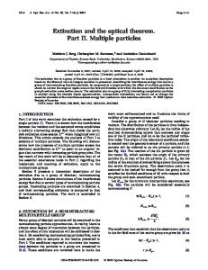
1. Introduction With the introduction of photonic crystal fibers in 1990s, the world saw new developments in the areas of optical communication technology. In recent years, photonic crystal fibers (PCFs) made up of pure silica and air holes have provided a new approach for designing dispersion compensating fibers (DCFs) with large negative dispersion. However, in PCFs large negative dispersion is always associated with very small effective mode area, leading to high splicing losses and undesirable nonlinear effects during optical signal transmission. In this paper, we propose a novel fiber design by combining the conventional all-solid dual core DCF [1,2] with dispersion compensating photonic crystal fiber (DC-PCF) [3,4]. The design has been realized by introducing a circular array of air holes in the inner cladding. Using this design, a high negative dispersion of 33000 ps nm-1 km-1 and large-mode-area (LMA) of 68 µm2 has been achieved. Due to high negative dispersion, a short length of fiber can efficiently compensate the accumulated dispersion in the optical fiber communication link. The proposed DCF owing to its large-mode-area will have low splice loss and reduced non-linear effects. 2. Fiber Design The fiber has been designed so as to utilize the properties of all-solid dual core DCF as well as DC-PCF. In addition to the flexibility provided by the structural parameters for dispersion management, the arrangement and size of air holes provide additional degrees of freedom for tailoring the dispersion characteristics effectively. The transverse cross section of the proposed DCF is shown in Fig. 1. The radius of inner core is a, the width of inner clad is d1 while the width of outer core is d2. The inner core consists of Ge-doped glass with relative index difference + . The inner cladding consists of pure silica with microstructured air holes arranged in concentric circular rings. The outer core is also Ge-doped and is surrounded by outer cladding made of pure silica.
Fig. 1. Cross section of the proposed fiber design. The dark gray region shows Germanium-doped inner and outer core of the fiber. The light gray region shows inner and outer cladding made of pure silica. The air holes are shown in white.
WPo.24.pdf
International Conference on Fiber Optics and Photonics © OSA 2012
3. Numerical Results and Discussion In the proposed design we have considered inner core radius a = 1.8 μm and outer core width d2 = 1 μm. The relative index difference between the Ge-doped cores and pure silica is Δ+ = 0.98%. The size of air holes and inner clad width have been optimized so as to have high negative dispersion. Dispersion and the corresponding mode effective area of the fiber have been calculated by using the full-vectorial Finite Difference Time Domain (FDTD) method. Fig. 2 shows the typical mode field pattern for the fiber at 1511.5 nm wavelength. The spectral variation of effective index neff of the fiber for both symmetric and antisymmetric supermodes has been plotted in Fig. 3. At shorter wavelengths, the mode is confined in the inner core and it gradually shifts towards the high-index Ge-doped outer core as the wavelength is increased. Due to highly asymmetric nature of inner and outer cores, there is a sharp change in the slope of the effective index near resonance wavelength which leads to large negative dispersion. This large negative dispersion can be achieved in PCF due to high-index difference between air and silica. Dispersion in the fiber has been calculated by using the following relation:
d neff 2
D
c d where λ is the wavelength and c is the speed of light in free space. 2
(1)
Fig. 2. Modal field intensity of the fundamental mode of the designed fiber at resonance wavelength.
Fig. 3. Spectral variation of effective indices of both symmetric and antisymmetric supermodes.
The dispersion coefficient of the fiber is plotted in Fig. 4. There is a characteristic drop in dispersion coefficient at the resonance wavelength. A very high negative dispersion of 33000 ps nm−1 km−1 has been obtained at resonance wavelength 1511.5 nm. The FWHM corresponding to this dispersion is 1.2 nm. With such high negative dispersion, ~ 50 m of the fiber will be needed to compensate the accumulated dispersion in a 100 km conventional single-mode fiber, which is approximately half the fiber length required for dispersion compensation in [2].
WPo.24.pdf
International Conference on Fiber Optics and Photonics © OSA 2012
Fig. 4. Dispersion curve of microstructured dual-core LMA fiber design.
Usually, the fibers with very high negative dispersion have considerably small mode areas in the range of 20-30 µm2 [3,4]. One of the special characteristic of this novel fiber design is the large effective area it offers at very high negative dispersion. Mode area for the fiber has been calculated by using the following relation [5]:
2 [ | ( r ) | rdr ] Aeff
2
2
0
(2)
| (r ) |
4
rdr
0
where ψ(r ) is the modal field of the symmetric mode. Fig. 5 shows the variation of mode area of the fundamental mode of the fiber with wavelength. A mode area of 68 µm2 has been obtained at wavelength of 1511.5 nm and the corresponding dispersion value is 33000 ps nm−1 km−1. To the best of our knowledge, this is the largest mode area that has been obtained at a high negative dispersion value of 33000 ps nm−1 km−1. The large-mode-area helps to reduce the splice loss while joining the fiber with standard optical fiber. For instance, the effective mode area of Corning® LEAF® fiber is 72 µm2 which is very close to that of the mode area of the fiber design proposed in the paper.
Fig. 5. Variation of mode effective area with wavelength.
4. Conclusion We have presented and analyzed a novel microstructured dual-core DCF by combining the designs of all-solid dual core DCF and DC-PCF. The dispersion characteristics of the present fiber design have been analyzed by full vectorial FDTD method. The fiber exhibits very large negative dispersion of around 33000 ps nm-1 km-1 and a large-mode-area of 68 µm2. Such a fiber should be useful for dispersion compensation in long haul communication. References [1] Thyagarajan K, Varshney R K, Palai P, Ghatak A K and Goyal I C, “A novel design of a dispersion compensating fiber,” IEEE Photon. Technol. Lett. 8, 1510–1512 (1996). [2] Rastogi V, Kumar R and Kumar A, “Large effective area all-solid dispersion compensating fiber,” J. Opt. 13, 125707 (2011). [3] Ni Y, Zhang L, An L, Peng J and Fan C, “Dual-core photonic crystal fiber for dispersion compensation,” IEEE Photon. Technol. Lett. 16, 1516–1518 (2004). [4] Huttunen A and Törmä P, “Optimization of dual-core and microstructure fiber geometries for dispersion compensation and large mode area,” Opt. Express 13, 627–635 (2005). [5] Agrawal G P, Nonlinear Fiber Optics (New York: Academic, 1989).