5358
Macromolecules 2004, 37, 5358-5363
Electrically Induced Patterning in Block Copolymer Films Hongqi Xiang, Yao Lin, and Thomas P. Russell* Polymer Science and Engineering Department, University of Massachusetts, Amherst, Massachusetts 01003 Received January 14, 2004; Revised Manuscript Received April 22, 2004
ABSTRACT: Thin films of block copolymers were manipulated on two different length scales simultaneously by use of an electric field. Electrostatic pressure generated at the surface of a block copolymer film between two electrodes with an air gap separating the surface of the block copolymer film and the upper electrode produced, as in homopolymer films, an array of hexagonally ordered columns, tens of microns in size, that spanned between the two electrodes. Within each column the diblock copolymer microphase separated into hexagonally packed cylindrical microdomains, tens of nanometers in size. The orientation of these microdomains was controlled by the interfacial energies of each block with the surfaces of the electrode and the direction of the applied field. Microdomain alignment parallel to and normal to the applied field could be controlled by the strength of the interfacial interactions. The results show a novel means by which block copolymers can be controlled on two different length scales simultaneously and present a new route toward fabricating functional nanoscopic structures in thin polymer films.
Introduction Block copolymers can self-assemble into a wide variety of periodic structures with characteristic length scales of several tens of nanometers. This has established block copolymers as an attractive, versatile route to produce scaffolds and templates for the fabrication of nanoscopic devices.1-3 Realizing the full potential of these materials in thin film applications, however, requires controlling the microdomain ordering and orientation, so as to tailor the continuous thin films into desired patterns. Control over microdomain alignment can be achieved by using controlled interfacial interactions, mechanical shear, epitaxy, electric fields, solvent evaporation, surface and temperature gradients, and surface patterning.4-14 Electric fields and controlled interfacial interactions are particularly attractive due to the simplicity of the process required to achieve alignment.8,11 As for micron/submicron scale patterning in block copolymer films, several approaches including embossing and soft lithography have been described.15,16 Of interest in this study is the use of an electric field to amplify the fluctuations on a polymer surface to generate well-ordered patterns on the micron to tens of micron size scale.17,18 The interaction of electric fields with dielectric materials is well understood. In essence, pattern formation induced from the electrohydrodynamic instability is of the same physical basis as that for the electrically induced domain orientation. The driving force for both processes is the orientation-dependent polarization in a material having dielectric interface.11,17 The electric field aligns interfaces separating two dielectric bodies parallel to the electric vector, thus minimizing the moment of electrostatic forces exerted onto the interface and the free energy of the system. In the case of block copolymers, the interface is formed from two chemically different blocks, whereas in thin films the surface of the film separates the polymer and air. This opens the
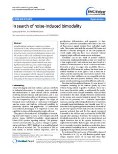
Figure 1. Schematic drawing of the experimental setup for electrically patterning diblock copolymer films.
possibility of coupling these two effects by applying an electric field to a thin block copolymer film so as to achieve pattern formation and domain alignment simultaneously. Here, we describe an easy method for nanostructure fabrication that couples the two interactions of electric fields with block copolymers and generates micron patterns with nanometer structure in one step. Diblock copolymer films between two electrodes with an air gap separating the surface of the film and the upper electrode, as shown in Figure 1, were used. Upon annealing the assembly above the glass transition temperatures of both blocks under an applied field, a well-ordered pattern of columns tens of microns in size was produced, and within each column a specific orientation of the block copolymer microdomains was obtained that depended on the interactions of each block with the electrodes and the applied field direction, as characterized by optical microscopy and transmission electron microscopy. Experimental Section
* To whom correspondence should be addressed: Tel +1-413-577-1535; Fax +1-413-577-1510; e-mail russell@ mail.pse.umass.edu.
Asymmetric diblock copolymers of polystyrene-block-poly(2-vinylpyridine) (PS-b-PVP), polystyrene-block-polyisoprene (PS-b-PI), and polystyrene-block-polybutadiene (PS-b-PBD)
10.1021/ma049888s CCC: $27.50 © 2004 American Chemical Society Published on Web 06/18/2004
Macromolecules, Vol. 37, No. 14, 2004
Figure 2. Optical micrograph of a PS-b-PVP film which has been exposed to an electric field. The 600 nm thick film was annealed at 180 °C for 24 h under an applied voltage of 30 V. were purchased from Polymer Sources. PS-b-PVP had a number-average molecular weight, Mn, of 102 000 and a polydispersity index, Mw/Mn, of 1.16; the PS-b-PI had a Mn ) 36 200 and Mw/Mn ) 1.02; and the PS-b-PBD had a Mn of 53 700 and a Mw/Mn of 1.04. The volume fractions of PVP, PI, and PS (in PS-b-PBD) in the corresponding block copolymers were all ∼0.3. Thus, in the bulk, the morphology consists of PVP cylinders in a PS matrix for PS-b-PVP, PI cylinders in a PS matrix for PS-b-PI, and PS cylinders in a PBD matrix for PS-b-PBD. Thin films of the copolymers (∼600 nm thick) were spincoated from toluene solutions onto polished silicon wafers that serve as one of the electrodes. An ITO glass slide was placed ∼2 µm from silicon wafer surface using a silicon oxide spacer, thus leaving a thin air gap. The silicon oxide spacers were evaporated on the conducting surface of the ITO glass. The assembly was then heated above the glass transition temperatures of both blocks (180 °C for PS-b-PVP and 125 °C for PSb-PI and PS-b-PBD), and 30 V was applied to the electrodes. After annealing for 24 h in a nitrogen atmosphere, the copolymer was quenched to room temperature. The upper ITO glass electrode was removed mechanically or etched away using a 5 wt % aqueous hydrofluoric acid solution. The structure of the thin film was investigated using an Olympus BX60 optical microscope in reflection mode. Bright field transmission electron microscopy (TEM) studies were performed with a JEOL 100CX TEM operated at an accelerating voltage of 100 kV. To prepare TEM specimens, a thin layer of platinum or carbon was evaporated onto the film surface to prevent the epoxy resin from diffusing into the copolymer film. The film was then embedded in epoxy resin and cured at 60 °C for 24 h. Ultrathin sections were prepared at room temperature using a Leica Ultracut microtome, equipped with a diamond knife. To enhance contrast, the thin PS-b-PVP sections were exposed to I2 vapors that preferentially stained the PVP block of the copolymer. For PS-b-PI and PSb-PBD, OsO4 vapor bath was used to stain the PI and PBD blocks.19
Results and Discussion Figure 2 shows a typical pattern formed in the block copolymer films. A hexagonally packed array of columns are seen, which protrude from an underlying thin PSb-PVP film. The columns were well-ordered, and no defect in the packing of the columns was found over a 500 µm × 500 µm area. A two-dimension fast Fourier transform (FFT) pattern of this micrograph is shown in the inset. Multiple higher order interferences were seen in the transform, indicating the high degree of
Patterning in Block Copolymer Films 5359
order in this single grain of hexagonally packed columns that bridged between the electrodes. The ordering of the column array originates from an electrostatic repulsion between the columns as they grow from fluctuations on the film surface. The size of the columns depends on the volume fraction of copolymer between the two electrodes, i.e., the air gap thickness relative to the copolymer film thickness.17 A higher ratio of film to the gap thickness will produce a more dense lateral arrangement of the columns and an improvement in their hexagonal order. Producing a well-ordered array over a large area requires that the two electrodes be parallel. It should also be noted that the column walls are not straight and have a curved contour (as evidenced later by the cross-sectional TEM images). This results from a wetting of the ITO glass by the copolymer. The time scale for the pattern formation is different from that of the microphase separation process. The growth rate of columns depends on the nature of the copolymer, surface tension, fluid viscosity, and the experimental configuration, including the applied electric field, copolymer film thickness, and air gap width.20 The characteristic times required to produce columns bridging the two electrodes are normally less than several hours. While the microphase separation of the block copolymer occurs rapidly, achieving domain alignment required a much longer time to reach a fully aligned state. Characteristic time ranged from several days to several weeks. In this study, all three block copolymers were in the strong segregation regime. Here, a 24 h annealing was used. To visualize the microphase separated morphology in the micron-sized columns, TEM studies were performed. The block copolymer film was microtomed perpendicular to the film surface, i.e., cutting the columns along their axis direction. Figure 3 shows the vertical cross-section TEM image obtained from the PS-b-PVP film under an applied voltage of 30 V at 180 °C for 24 h. The evaporated carbon and platinum layers were visible at the boundary between the film and embedded epoxy resin and highlighted the outline of the columns. The contour of the sidewalls of the columns induced by the wetting of both electrode surfaces is evident. The PVP phase was preferentially stained with I2 and appeared darker than the surrounding PS matrix. In the columns, microphase-separated domains were well developed, although it was not easy to discern which phase segregated to the electrode interfaces and the sidewalls of the columns. The circular-shaped sections for PVP cylindrical domains indicate that the PVP cylinders were oriented parallel to the substrate surface rather than parallel to the electric field direction. Such a domain orientation was also observed for the PS-b-PI columns grown under the same experimental condition but at 125 °C. As shown in Figure 4, the vertical sectioning showed hexagonally packed black circles of the OsO4-stained PI phase against a white background of unstained PS phase, indicating a parallel orientation of hexagonally packed PI cylinders to the substrate. In both cases, the effect of electric fields on microdomain alignment was not evident. Rather, the interfacial interactions dominated and propagated through the entire column. Though not evident, both PVP and PI are known to preferentially segregate to both surfaces, and the applied field is not sufficient to overcome these interactions. This also suggests that the dielectric constant differences between the microdomains are not
5360 Xiang et al.
Macromolecules, Vol. 37, No. 14, 2004
Figure 3. TEM vertical cross-sectional image of PS-b-PVP columns.
Figure 4. TEM vertical cross-sectional image of PS-b-PI columns.
sufficiently large to produce a large enough field differential to orient the domains in the vicinity of the surface. In the case of PS-b-PBD columns, however, the influence of the electric field on the microdomain alignment was observed. Figure 5 shows a crosssectional TEM image of PS-b-PBD column outlined by an evaporated platinum layer. The cylindrical PS microdomains appeared bright against the dark PBD matrix which was stained with OsO4. As can be seen,
the cylindrical PS microdomains appear as lines since they have been cut along the axis of the cylinders. In addition, the cylindrical microdomains are tilted with respect to the field lines. This more than likely arises from the interaction of the cylinders with the side walls of the columns. The preferential alignment of PBD to this air interface is driven by the lower surface energy of the PBD. The curvature of the column walls, in turn, forces the misalignment of the microdomains. Nonetheless, the results clearly show that the electric field
Macromolecules, Vol. 37, No. 14, 2004
Patterning in Block Copolymer Films 5361
Figure 5. TEM vertical cross-sectional image of PS-b-PBD columns.
strongly orients the microphase-separated domains in PS-b-PBD. To understand the different domain alignment for the three copolymer systems, the effect of substrates and surface interactions must be considered. It is wellknown from thin film studies that a free surface or an interface can force a parallel alignment of the block copolymer microdomains when there is a preferential segregation of the constituent blocks. In general, the block with the lower surface energy will segregate to the free surface and one block will preferentially segregate to the substrate interface. In this study, the original film thickness was ∼600 nm and the column height ∼2 um. Consequently, the effect of a surface or interface on microdomain alignment could not be neglected. In fact, there is a competition between the surface fields and the applied electric field. The preferential segregation of one block to a surface or interface originates from the difference in interfacial energies between the two blocks. The strength of the driving force for parallel orientation is, therefore, proportional to ∆γA-B ) |γA - γB|. The electric-field-induced alignment in block copolymers is a consequence of the difference in the dielectric constants between the two constituent blocks.11 Hence, this driving force is proportional to ∆�A-B ) |�A - �B|. Table 1 lists the dielectric constants and surface energies for the blocks of the copolymers employed in this study. In the case of PSb-PI, both the dielectric constant and the surface energy of PI are very close in value to those of PS. There are only weak forces in play with this copolymer. This is evident in the micrograph shown in Figure 4, where a disordered array of cylinders oriented parallel to the surface of the electrodes are seen. As for PS-b-PVP, even though the ∆�PS-PVP is large, there is a large difference in the interfacial energies ∆γPS-PVP. While both the surface and electric fields are acting on the microdomain alignment of the PS-b-PVP in two orthogonal directions, the surface field clearly dominates aligning the micro-
Table 1. Physical Properties of the Blocks of Copolymers Employed polymer
dielectric constant,a � (Hz)
surface energy,b γ (mN/m)
polystyrene poly(2-vinylpyridine) polyisoprene polybutadiene
2.4-2.7/103 4.64/103 2.37/103 3.3/106
33-36 34/170-200°C 30-32 31-34
a Ku, C. C.; Liepins, R. Electrical Properties of Polymers: Chemical Principles; Hanser Publisher: Munich, 1987. b Brandrup, J., Immergut, E. H., Eds. Polymer Handbook, 3rd ed.; John Wiley & Sons: New York, 1989.
domains within the columns parallel to the interface. With PS-b-PBD, however, ∆� between the two blocks is large. In fact, the dielectric constant of polybutadiene is so large that it was measured at a higher frequency than the other polymers. This character of styrenebutadiene copolymers enable a strong influence by the electric field, orienting the microdomains within the columns normal to the interface, i.e., in the direction of the applied electric field. The response of the block copolymer to an applied electric field depends, of course, on the strength of the electric field. Since the electric field strength depends on the geometric configuration of the dielectrics, understanding the electric field distribution during the growth of the columns is necessary to understand the competition between the electric field and surface effects. In this study, the applied voltage U was only 30 V due to a practical limitation. The electric potential distributed onto the copolymer layer was reduced due to the presence of an air gap in the experimental setup. Initially, there were a ∼600 nm copolymer layer and a ∼1.4 um air layer between the parallel electrodes. The voltage distributed on the copolymer layer can be written as
Ucopolymer ) U/(1 + (hair�copolymer/hcopolymer))
5362 Xiang et al.
where �copolymer is the average dielectric constant of the block copolymer and hair and hcopolymer are the layer thickness of the air gap and copolymer film, respectively. Taking 3 as the value for �copolymer, for example, a drop in the effective voltage applied to the copolymer film is only 3.75 V. As the columns grow, the electric field distribution also changes. Only after the columns touch the upper electrode is the full field experienced by the copolymer. Thus, in general, the surface field is stronger than the applied electric field initially. Upon annealing, the block copolymer near the surface and interface microphase separates rapidly with an orientation parallel to the interface. As the columns grow, the electric field within the polymer increases and may ultimately surpass the surface field, inducing an orientation or reorientation of the microdomains parallel to the field direction. The critical electric field required for a microdomain alignment transition in copolymer thin films can be calculated by equating the free energies in two orthogonal orientations induced by the electric field and surface interactions, respectively. It has been shown, however, that an electric field intensity higher than that predicted from simple thermodynamic arguments is required.21 To understand this phenomenon, the kinetics of the alignment transition process must be considered. There are two possible routes to reorient the microdomains. One is a simple rotation of the microdomain grains. The energy barrier to complete this rotation in copolymer melts is so high that this route is actually not feasible. A more plausible route is through an undulation of the microdomains. This, however, increases the interfacial area between the microdomains and also sets an energy barrier, though not so high as that of rotating microdomain grains. Hence, it is quite reasonable that a transition of microdomain alignment from surface energy dominated to electric field dominated was seen only for PS-b-PBD, where a strong interaction with the electric field and a much reduced viscosity compared to those of the other two copolymers are expected. It should be noticed that the morphologies shown in the TEM images do not correspond to the equilibrium morphologies. Rather, the morphologies are the frozen states of two kinetic processes in competition, namely the electricfield-induced alignment and the surface-induced alignment of the microdomains. Throughout the formation and growth of the microscopic columns, the copolymer is continuously being drawn into the column from the reservoir adjacent to the lower electrode. The flow field occurring during this time will, of course, produce an alignment of the copolymer. Subsequently, a reorientation of the copolymer will occur either in the direction of the applied field or parallel to the electrode surfaces. The microphase separation of the block copolymer will retard the flow of the copolymer into the columns, yet it is clear that flow occurs and it will be influenced by the shape of the column. Remnants of the flow can be seen in Figure 5 where the curvature of the column has caused a flow normal to the column walls in the center, i.e., normal to the field lines, and at the edges of the column where the film extends to wet the electrode surfaces. On both the top and bottom electrodes microdomains aligned parallel to the edge (or surface) of the columns are seen. Figure 6 shows a cross-sectional image for the PS-bPVP columns where the sample was cut normal to the column axis. Aligning the cutting plane to be absolutely
Macromolecules, Vol. 37, No. 14, 2004
Figure 6. Horizontal cross-sectional TEM image of PS-b-PVP columns.
normal to the column axis was experimentally difficult. As can be seen, elliptical, rather than circular, cross sections were obtained. Even still, information relevant to the microdomain orientation can be obtained. In the ellipse, at least two different domain orientations can be discerned. One parallel to the field lines, which shows circularly shaped PVP domains. The other is normal to the applied field which shows line-shaped PVP microdomains. These results are consistent with the TEM results in Figure 3. The results also show that the microdomain ordering has yet to be strongly influenced by interactions with the sidewalls of the column. Such surface-induced ordering would be expected, but from these data, it is evident that a longer annealing time would be required. Conclusion In summary, a one-step method to pattern block copolymer films on two different length scales simultaneously was shown. This approach couples the response of block copolymer films to an external electric field, the enhancement of surface fluctuations in copolymer films to form columnar structures, and the electric-fieldinduced alignment of microphase-separated domains. Upon applying an electric field across a copolymer film, a hexagonal array of columns (tens of microns in diameter) was formed by the copolymer film. Within the columns, the microphase-separated microdomains were oriented. The orientation achieved depended on two competing fields: interfacial interactions and applied electric field. By tuning the nature of the interfacial interactions, columns with cylinders oriented either parallel to or normal to the direction of the applied field was produced. This patterning technique is straightforward and can be applied in facile nanofabrication. Acknowledgment. The authors thank Louis Raboin for technical assistance with TEM characterization. Financial support of NASA, the National Science Foundation, the National Science Foundation-supported Material Research Science and Engineering Center (MRSEC) at University of Massachusetts, Amherst, and the Department of Energy, Office of Basic Energy Science, is gratefully acknowledged. References and Notes (1) Park, M.; Harrison, C.; Chaikin, P. M.; Register, R. A.; Adamson, D. H. Science 1997, 276, 1401.
Macromolecules, Vol. 37, No. 14, 2004 (2) Thurn-Albrecht, T.; Schotter, J.; Kastle, G. A.; Emley, N.; Shibauchi, T.; Krusin-Elbaum, L.; Guarini, K.; Black, C. T.; Tuominen, M. T.; Russell, T. P. Science 2000, 290, 2126. (3) Chan, V. Z.-H.; Hoffman, J.; Lee, V. Y.; Latrou, H.; Avgeropoulos, A.; Hadjichristidis, N.; Miller, M. D.; Thomas, E. L. Science 1999, 286, 1716. (4) Hamley, I. W. The Physics of Block Copolymers; Oxford University Press: Oxford, 1998. (5) Amundson, K.; Helfand, E.; Davis, D. D.; Quan, X.; Patel, S. S. Macromolecules 1991, 24, 6546. (6) Morkved, T.; Lu, M.; Urbas, A. M.; Ehrichs, E. E.; Jaeger, H. M.; Mansky, P.; Russell, T. P. Science 1996, 273, 971. (7) Boker, A.; Knoll, A.; Elbs, H.; Abetz, V.; Muller, A. H. E.; Krausch, G. Macromolecules 2002, 35, 1319. (8) Huang, E.; Rockford, L.; Russell, T. P.; Hawker, C. J. Nature (London) 1998, 395, 757. (9) Fasolka, M. J.; Harris, D. J.; Mayes, A. M.; Yoon, M.; Mochrie, S. G. J. Phys. Rev. Lett. 1997, 79, 3018. (10) Hashimoto, T.; Bodycomb, J.; Funaki, Y.; Kimishima, K. Macromolecules 1999, 32, 952. (11) Thurn-Albrecht, T.; DeRouchey, J.; Russell, T. P.; Jaeger, H. M. Macromolecules 2000, 33, 3250.
Patterning in Block Copolymer Films 5363 (12) Kim, S. H.; Misner, M. J.; Xu, T.; Kimura, M.; Russell, T. P. Adv. Mater., in press. (13) Rockford, L.; Liu, Y.; Mansky, P.; Russell, T. P.; Yoon, M.; Mochrie, S. G. J. Phys. Rev. Lett. 1999, 82, 2602. (14) Kim, S. O.; Solak, H. H.; Stoykovich, M. P.; Ferrier, N. J.; de Pablo, J. J.; Nealey, P. F. Nature (London) 2003, 424, 411. (15) Fichet, G.; Stutzmann, N.; Muir, B. V. O.; Huck, W. T. S. Adv. Mater. 2002, 14, 47. (16) Deng, T.; Ha, Y.-H.; Cheng, J. Y.; Ross, C. A.; Thomas, E. L. Langmuir 2002, 18, 6719. (17) Schaffer, E.; Thurn-Albrecht, T.; Russell, T. P.; Steiner, U. Nature (London) 2000, 403, 874. (18) Chou, S. Y.; Zhuang, L. J. Vac. Sci. Technol. B 1999, 17, 3197. (19) The PS-b-PBD specimen were first stained with OsO4 and then microtomed at room temperature. (20) Schaffer, E.; Thurn-Albrecht, T.; Russell, T. P.; Steiner, U. Europhys. Lett. 2001, 53, 518. (21) Xu, T.; Hawker, C. J.; Russell, T. P. Macromolecules 2003, 36, 6178.
MA049888S