Low Dielectric Constant Materials: Challenges of Plasma Damage M.R.Baklanov, A.Urbanowicz, G.Mannaert and S.Vanhaelemeersch IMEC, Leuven, Belgium e-mail:
[email protected]
Abstract Degradation of porous low dielectric constant materials during their exposure in etch and strip plasmas is analyzed from point of view of surface chemistry and recombination of active radicals. Although the degree of damage during the etching can be significantly reduced, the damage in O2 and H2 based strip/cleaning plasma are more challenging. The plasma damage mechanisms are the main subject of this discussion. It is demonstrated why the degree of damage can be reduced using He and H2 based plasmas at elevated processing temperature. 1. Introduction Materials with low dielectric constant (low-k) are required as interlayer dielectrics for on-chip interconnects of ultralarge-scale integrated (ULSI) devices to provide high speed, low dynamic power dissipation and low cross-talk noise. K value reduction is obtained through selection of the appropriate chemical compounds in the film and through introduction of porosity. Advanced low-k films are mainly based on Silica and Silsesquioxanes with 10-15% of organic hydrophobic groups. The hydrophobic groups are needed to avoid moisture adsorption that increases the effective dielectric constant. These groups are normally bonded to Si atom in SiO4/2 matrix and can be represented as O3≡Si-CHx. The matrix of these materials have the ks-values lower than pure SiO2 because the organic groups decrease the polarisability and density. However, to reach a k-value below 3.0, introduction of artificial porosity is needed [1]. Advanced low-k materials have porosity 30-50%, a typical pore size being close to 2-2.5 nm. Introduction of porosity creates integration challenges related to diffusion of active radicals into the film during Reactive Ion Etching (RIE) and cleaning and their reaction with the film components. Damage of low-k materials is related to removal of organic hydrophobic groups, densification of the top surface by ion bombardment and photochemical modification initiated by
vacuum ultraviolet (VUV) photons generated by etch and strip plasmas. The removal of hydrophobic groups by O and H radicals present in etch and strip plasmas is the major reason of damage. Damage of low-k materials during RIE can be significantly reduced when an O2 free fluorocarbon plasmas is used [2]. Not only the lack of oxygen radicals but also CFx polymer deposited in the top part of the pores reduces penetration of active radicals and damage of internal pore surface. For this reason, we will mainly concentrate on analysis of plasma damage in strip/cleaning plasmas containing O2, H2, N2, and NH3. The analysis covers a wide range of experimental conditions: ion energy was varied from almost zero to a few hundred eV, temperature range was from 20˚C to 300˚C and the pressure varied from mTorr range to several Torr [3]. 2. Experimental Experiments were done with Silica based low-k films deposited by Spin-On-Glass (SOG) technology. Carbon concentration was about 10-12%, porosity close to 30% and pore size about 2 nm. Three different asymmetric parallel-plate type plasma reactors were used for the evaluation of plasma damage. The first reactor (R1) is used to reduce CuO before TaN barrier deposition. Cleaning by Ar ions (PC) was carried out at P=0.5 mTorr and bias voltage 260 V. The same chamber is also used for cleaning by H2/He plasma (RPC) at P=80 mTorr and estimated bias ≤ 100 V. The second reactor (R2) is a RIE, where typically O2, O2/CF4, O2/SF6 and N2/H2 plasmas are used for resist strip. The pressure was in the 100-350 mTorr range and the bias voltage was close to 100 V. The R3 reactor is used for Cu surface cleaning before PECVD dielectric barrier deposition. This reactor had the highest gas pressure in the range of 6-9 Torr. The wafer is placed on the grounded electrode and gets min ion bombardment.
3. Discussions These data demonstrate that the degree and type of plasma damage depend on chemistry, pressure, temperature and ion energy. He pre-treatment decreases the damage, especially at moderate temperatures. The low degree of hydrophilisation in R1 (Ar PC) suggests the densification itself, without carbon depletion, is less important in comparison to the carbon depletion.
Plasma damage is a field of intensive research. All published papers show that O2 based plasmas cause significant chemical modification. The situation with H2 based plasma’s is more complicated. Different authors reported no effect on the film, enhancement of the film properties up to severe damage [5]. The apparent contradiction can be understood if one takes into account specific features of H2 based plasmas. The role of additives, radical diffusion into pores, their surface reactions and recombination must be taken into account. For instance, the dependency of the depth of damage on pore size and porosity is a clear evidence of important role of radical diffusion [6]. 48
Thickness loss [nm]
44 40 36 32 28 24 20 16 12 8 4 1
2
3
4
5
6
1
2
3
4
5
6
8PC 6
5
6
7
8
9
10
11
12
13
14
15
16
17
18
19
20
21
22
7
8
9 10 11 12 13 14 15 16 17 18 19 20 21 22
22
Water adsorption [%]
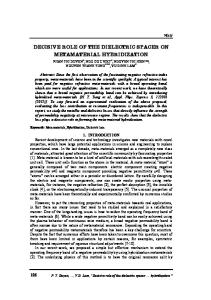
Different techniques such as FTIR, XPS and TOF-SIMS (chemical composition and depth profile), Ellipsometric Porosimetry (EP) (porosity, hydrophilicity), surface contact angle, dielectric constant measurements (Hgprobe) have been used for the evaluation. The degree of hydrophilisation (as a measure of plasma damage), change of composition and densification, as well as the depth of modification depends on the plasma conditions. The hydrophilicity measured by EP with water source (wEP) [4] correlates with the results of FTIR inspection and capacitance measurements (Hg probe). Figure 1 summarizes most of observed phenomena. The hydrophilicity was low after R1 (both PC and RPC) and after R3 when the films are consequently treated by He and NH3/N2, and H2 plasma. The degree of damage in RPC H2/He plasma decreases with increasing temperature. At T≈300°C the hydrophilicity was similar to the pristine low-k film. The highest hydrophilisation is observed after N2/H2 in R2 and NH3 based plasmas in R3. The negative effect of H2 based plasma can be reduced when a He plasma treatment is done prior to the NH3 plasma (R3) or He is mixed with H2 (R1). All these data correlate with the results of XPS and TOF SIMS analysis. Thickness loss and change of refractive indices are mainly related to the surface densification as evidenced by Spectroscopic Ellipsometry. The degree of densification is limited after O2/CF4 plasma (R2), He+NH3/N2 plasma (R3) and H2/He plasma (R1). Higher densification is observed after Ar PC, which suggests that the ion bombardment plays a key role in densification. Significant densification was also observed in R2 (N2/H2). According to XPS and TOF SIMS results, the densification during Ar PC happens without significant carbon depletion and the films remain quite hydrophobic. Hydrophilisation in N2/H2 and NH3 plasmas in R2 and R3 are accompanied with significant carbon depletion. Comparison of Ar PC (Ch1) and NH3/N2 in Ch3 shows that the energetic ions (R1) play minor role in hydrophilisation in comparison with purely chemical factor (R3).
20 18 16 14 12 10 8 6 4 2
3 7 Series1 P
P [Torr] Bias [V]
-3 0.5×10 0.5×10⁻³
260 260
5 4 RPC
3 13 14 16 16 RIE 16 16 16 15 16 20 21 6 3 PECVD
80×10-3 ≤100 10 10
(150 - 350)×10-3 ≤100 100 100
6 - 8.7 <10
Figure 1: Change of thickness and hydrophilicity after different plasma treatments. 1: pristine sample; 2-5: Ar PC at 20, 150, 200 and 300°C, respectively; 6-9: He/H2 RPC at 20, 150, 200 and 300°C; 10-11: O2/CF4 (1:200) at 20/75°C; 12-13: Ar/H2 20/75°C; 14-15: N2/H2 (1:2) at 20/75°C, 16-17: N2/H2 (5:1) at 20/75°C; 18: N2/H2/CF4 at 20°C; 19-20: NH3 and NH3/N2 plasmas at 350°C; 21: He + NH3/N2 (350°C) and pure H2 (350°C).
3.1 Depth of damage. The depth of damage should correlate with depth of penetration of active radicals. Complete resist strip and residue removal needs certain over-exposure (overetch) time. At the point of complete removal of the of the resist, the effective radical concentration in the cleaning chamber is increased (macroloading effect). Therefore, the degree of
N A = − DA dC A dx . The material balance on a differential
length
πdp
of pore is:
⎛ dC ⎞ ⎛ dC ⎞ π d p DA ⎜ A ⎟ + DA ⎜ A ⎟ + π d p dxk R C A (1) − 4 4 ⎝ dx ⎠ x + dx ⎝ dx ⎠ x The first term of eq.(1) reflects the flux into the region x+dx, the second term is the flux out of this region. The third term represents the radical consumption inside the region x+dx due to the reaction with Si-CH3 (kreact) and recombination (krecomb): kR=kreact+krecomb. Analytical solution of equation (1) shows that the depth of radical penetration depends on ratio of kr to DA (λ), which is termed as Thiele Modulus (TM): 2
2
1/ 2
⎛ 4k r ⎞ d 2C A ⎟ − λ2C A = 0, where λ = ⎜⎜ 2 ⎟ dx ⎝ d p DA ⎠ 1 .2 Carbon concentration (a.u.)
damage strongly depends on overexposure, which, on the other hand, depends on properties of radicals used for the strip. Figure 2 shows the time dependent plasma damage using 2 different strip plasmas. One can see that the degree of damage in N2/H2 plasma depends on the exposure time while the degree of damage in an O2/SF6 based plasma is higher and reaches a stationary level at a relatively short strip time. Similar study with O2/CF4 plasma showed that the degree of damage depends on the fluorine concentration. When the CF4/O2 ratio is less than 1/50, the damage is similar to the one, obtained in a pure oxygen plasma, at higher fluorine concentration, the damage increases. SF6 plasma is more fluorine rich and therefore the maximum damage is succeeded at lower exposure time. All these data are supported by the results of TOF SIMS analysis. These phenomena suggest that the dynamic character of damage is important for understanding and optimization of technological processes.
1 0 .8 0 .6 0 .4 0 .2 0
Figure 2. FTIR spectra of a low-k film exposed in N2/H2 plasma in the range 3000-3800 cm-1, reflecting amount of adsorbed moisture. Kinetics of plasma damage depends on reactivity of the radicals and features of their diffusion into low-k materials. Let’s consider radicals diffusion into single pores with diameter dp. It is reasonable to assume that radical concentration (CA) is uniform in plasma reactor because of low pressure. It has also been proven that the depth of damage during the strip is normally less than the film thickness. Therefore, at a certain depth x=L (close to 30-40 nm [7,8]) CA=0. Diffusion flux inside the pore is
λ = 0 .1 λ = 0 .2 λ = 0 .5
0
2
4 6 8 10 12 14 16 D e p th o f d a m a g e (a .u .)
Figure 3. Change of CHx concentration versus depth at different values of Thiele Modulus. Figure 3 shows the calculated change of carbon concentration versus depth at different TM values. It is clear the depth of damage can be limited by thin surface area if the TM value is high (kR>>DA). As we already mentioned, kR is a sum of two different values. To estimate, which one has more influence to the TM value, let’s make the following estimations. The measured resist strip rates in R2 were close to 2500 nm and 700 nm in O2/CF4 and N2/H2 plasmas respectively. The C-C and Si-C bond energies have quite close values. Therefore we can assume that the removal of hydrophobisation agents in low-k film occurs with a specific rate similar to the resist strip rate. Taking into account that the low k film has a porosity of 30% and the CHx concentration is close to 10%, we can estimate that the complete radical consumption due to reaction with the hydrophobisation agent will create damage with depth exceeding 500 nm. This is more than an order of magnitude higher as compared to the experimental observation. Therefore, one
can conclude that the main way of radical consumption is their recombination during the diffusion. 3.2. How to increase TM values? The discussions above demonstrate that we have to find ways to increase TM values. Two different ways are obvious. We can increase the recombination rate by changing experimental conditions, for instance, by changing process temperature. The recombination rates of the major players of the strip process (H, O, N) were extensively studied. It has been established that recombination of H atoms has more pronounced temperature dependence (41 kJ/mol) in comparison with O and N radicals (17 and 14 kJ/mol, respectively). This explains reduction of plasma damage in a He/H2 plasma (Figure 1) and Ar/H2 based plasmas with increasing processing temperature [5]. Probably this also explaines the low damage when a H2/He plasma is used at temperatures close to 300°C [8]. The second possible way to increase the Thiele Modulus is through activation of the surface area of low-k films in order to increase the recombination rate. The most obvious and simple way is through deposition of fluorocarbon polymer during the etching [2]. The fluorocarbon polymer fills the top part of pores and drastically reduces the diffusion rate of active radicals. As a result, most of the active radicals recombine in the top part of the film and damage reduction is observed. More interesting phenomena are related to using plasmas based on He/H2 mixtures and pure H2. The positive effect of He/H2 plasmas is demonstrated in Figure 1. Pure H2 plasma allows stabilization of MSQ films and make them more resistant to the following O2 plasma [9]. One can see that the behavior of H2 and He/H2 plasmas is quite different from N2/H2 and Ar/H2 plasmas, which also have hydrogen as an active component. To understand this phenomenon we can consider discharge properties of H2, He and H2/He discharges. The main feature that differs these plasmas from discharges based on other mixtures is the emission of VUV photons. The chemical activity of this light has been proven. For instance, it is known that UV light generated by F2 excimer laser with λ=157 nm destruct SiO2 surface with formation of non-bridging oxygen hole centers [10], reducing native oxide on a Si surface [11]. Making use of the radiation of pure a He plasma to modify surfaces of low-k films has been demonstrated [12]. Even more energetic photons with energy q x 13.6 eV with q=1,2,3,7,9,11 are produced by He/H2 plasmas [13]. These features of plasmas containing
He and H2 are most probable the reasons explaining their different behaviors. The activated surface increases the rate of recombination of active radicals on the surface area of low-k materials reducing degree and depth of their damage. There is less available information about effects of fluorine additives. A possible reason is stabilization of an F-doped Silica surface that might reduce the rate of radical recombination [14]. 4. Conclusions. Plasma damage of low-k materials during the strip and cleaning depend on many experimental characteristics such as temperature, pressure, energy and intensity of ion bombardment and chemical composition of plasma forming gases. The most advanced ways of reduction of plasma damage are based on stimulation of surface recombination of active radicals to prevent their deep penetration into the low-k films. Hydrogen based plasmas at elevated temperatures look promising because of higher temperature dependence of recombination rate of hydrogen radicals. H2/He plasmas are also able to stimulate surface reactions via VUV emission and also stimulated recombination rate and reduce depth of damage. Although the ideas presented allow explanation of many observed phenomena, effects of VUV photons and fluorine additives on plasma damage during strip still needs more extensive experimental and theoretical evaluation. This work was done within the frame of the IMEC Industrial Affiliation Program on Advanced Interconnects. References [1] [2] [3] [4]
K. Maex et al. J.Appl.Phys. 93(11), p. 8793 (2003). G.Mannaert et al. J.Vac.Sci.Technol., B23, p.2198 (2005). A.M.Urbanowicz et al. UCPSS’2006, Antwerpen, Belgium. M.R.Baklanov et al. Microel. Eng., to be published.
[5] M.A.Worsley et al. J.Vac.Sci.Technol., B23, p.395 (2005). [6] M.R.Baklanov et al. In: Silicon Nitride, Silicon Dioxide, Thin Insulating Films and Other Emerging Dielectrics YΙΙΙ, Ed. R.E.Sah et al. ECS, PV 2005-1, p.179 (2005). [7] M.R.Baklanov et al. IITC’2004, San Francisco, 2004. [8] Q.T.Le et al. ISTC’2006, Shanghai, 2006. [9] P-T. Liu et al., Jpn.J.Appl.Phys., 38, 3482 (1999). [10] H.Hosono et al. Appl.Phys.Lett., 74, 2755 (1999). [11] Y.Takakuwa et al. Jpn.J.Appl.Phys., 28,1274 (1989). [12] K.Yanai et al. MRS Symp.Proc., 863, B2.3.1 (2005). [13] R.Mills et al. J.Phys. D: Appl.Phys., 36, 1535 (2003). [14] M.Mizuguchi et al., J.Vac.Sci.Technol. B17, 3280 (1999). K.Saito et al., J.Appl.Phys., 91 4886 (2002)