Journal of The Electrochemical Society, 157 共5兲 H565-H573 共2010兲
H565
0013-4651/2010/157共5兲/H565/9/$28.00 © The Electrochemical Society
Effects of He Plasma Pretreatment on Low-k Damage during Cu Surface Cleaning with NH3 Plasma A. M. Urbanowicz,a,b,*,z D. Shamiryan,a A. Zaka,a,c P. Verdonck,a S. De Gendt,a,b,** and M. R. Baklanova a
IMEC, Leuven, Belgium B3001 Chemistry Department, Katholieke Universiteit Leuven, Leuven, Belgium B3001 Materials Engineering Department, Institut National des Sciences Appliquées de Lyon, Villeurbanne, France 69621
b c
In this study, the effect of the sequential He and NH3 plasma treatments on a chemical vapor deposition SiOC:H low-k dielectric is evaluated in the wide range of experimental conditions. Results show that the active NH3 plasma radicals penetrate the porous low-k bulk and remove the hydrophobic Si–CH3 groups, which leads to hydrophilization and results in the degradation of dielectric properties. The implementation of He plasma pretreatment reduces the damage imposed by the NH3 plasma by a stimulation of the surface recombination of active radicals from NH3 plasma. He plasma causes a surface modification of 10–20 nm presumably due to the energy transfer from the extreme UV photons and the 21S He metastable atoms to the low-k structure. The plasma damage reduction is proportional to He plasma density and the treatment time. The mechanism of plasma damage reduction is explained on the basis of the Knudsen diffusion mechanism and random walk theory. © 2010 The Electrochemical Society. 关DOI: 10.1149/1.3355881兴 All rights reserved. Manuscript submitted January 12, 2009; revised manuscript received January 6, 2010. Published April 7, 2010.
The integration of porous low dielectric constant 共low-k兲 materials is a persistent issue in microelectronics industry.1 One of the most difficult challenges is related to the high sensitivity of porous materials to chemicals and plasmas. Pores and their connectivity significantly increase the penetration depth of active species during different technological processes such as plasma etching and cleaning, deposition of barrier layers, and chemical mechanical polishing 共CMP兲.2 The most severe damage of low-k materials occurs during their exposure to strip/cleaning plasmas containing oxygen or a mixture of nitrogen and hydrogen. The active radicals formed in these plasmas are able to remove carbon-containing hydrophobic groups with the formation of volatile compounds such as CO, CO2, H2O, and CH4. The formation of these compounds is thermodynamically favorable. As a result of the carbon depletion, the films become hydrophilic.1,3 Subsequent moisture absorption in the pores significantly increases the k-value due to the high polarizability of water molecules. All these phenomena have been extensively studied and documented for the resist strip and post-dry-etch cleaning.4 However, some additional issues are related to the cleaning of the Cu/low-k stack after planarization by CMP. The purpose of the postCMP cleaning is the reduction of Cu oxide on the Cu surface. Therefore, only reducing plasmas can be used for this purpose. NH3 plasma treatment is a popular approach because this plasma enables both the reduction of Cu oxides without deterioration of the adhesion with the subsequent dielectric liner and the removal of residual particles.5,6 However, NH3 plasma treatment leads to a significant modification of the chemical composition and degradation of low-k films 共carbon depletion and subsequent hydrophilization兲. This degradation is related to the penetration of active radicals from NH3 plasma into porous low-k materials. Therefore, low-k materials with porosity larger than 20% require process optimization with respect to plasma damage. One of the effective strategies to reduce bulk low-k damage is surface activation to trap the radicals at the surface. The reduction of O and NO2 plasma damage by using He plasma pretreatment in a plasma-enhanced chemical vapor deposition 共PECVD兲 chamber were reported by Wang et al.7 and Yanai et al.,8 respectively. However, the mechanism of plasma damage reduction was not discussed. Authors reported4,5,9 that the preliminary exposure of the low-k surface to He plasma makes it more resistant to NH3 plasma and pro-
* Electrochemical Society Student Member. ** Electrochemical Society Active Member. z
E-mail:
[email protected]
posed the mechanism of plasma damage reduction. The extreme ultraviolet 共EUV兲 emission from He plasma creates chemically active sites and decreases pore radii on the low-k surface, which leads to the recombination of active radicals on the surface. In certain cases, the activated surface could stimulate and localize chemical reactions, providing sealing of low-k materials. In this work, we discuss the effect of the NH3 plasma on the low-k dielectric and the effect of He plasma pretreatments at different radio-frequency 共rf兲 powers and exposure times on the NH3 plasma damage resistance of the low-k dielectric. We demonstrate, in addition to our previous work,9 that the low-k bulk damage reduction in the sequential plasma He + NH3 treatments is proportional to He plasma density. Furthermore, we discuss a model to describe key parameters for the plasma damage reduction in the sequential He + NH3 treatment on the basis of the Knudsen diffusion mechanism and random walk theory. Finally, we show that differential Fourier transform IR 共FTIR兲 spectroscopy can be used to monitor the pore sealing efficiency in the sequential He + NH3 plasma treatment. Experimental Dielectric material.— Porogen-based Aurora® ELK 共extreme low-k兲 HM 共high modulus兲 low-k films from the American Society of Metals 共ASM兲 with a k value of 2.5 were used for the experiments.10 Approximately 180 nm thick films were deposited on 300 mm Si wafers by PECVD. The porosity of the deposited low-k films was typically close to 25% with a mean pore radius of 0.7 nm, measured by ellipsometric porosimetry 共EP兲.11,12 Plasma treatment conditions.— All experiments were carried out in the Eagle 12 plasma chamber from ASM. This reactor is a capacitive-coupled plasma 共CCP兲 system. Using an rf of 13.56 MHz, the rf power was varied from 400 to 1400 W. The effect of ion bombardment was minimized because a wafer sat on a grounded electrode. The wafer temperature was approximately 350°C. For the damage evaluation, blanket low-k films were exposed to NH3, He, and successive He and NH3 plasma treatments. The experimental conditions are summarized in Table I. The effect of the NH3 plasma was evaluated after the exposure of low-k samples to 900 W NH3 plasma for 15 s at a gas pressure of 530 Pa and a gas flow of 400 sccm. Successive He ⫹ NH3 plasma treatments.— He plasma exposure was followed by the NH3 plasma exposure. The NH3 plasma treatment was the same for all experiments 共as described above兲. All the He pretreatments were performed using the same gas pressure of 630 Pa and gas flow of 1000 sccm. Two parameters of He plasma
Downloaded 08 Apr 2010 to 146.103.254.11. Redistribution subject to ECS license or copyright; see http://www.ecsdl.org/terms_use.jsp
H566
Journal of The Electrochemical Society, 157 共5兲 H565-H573 共2010兲
Table I. Summary of experimental conditions. Parameter Time 共s兲 Pressure 共Pa兲 RF power 共W兲 He flow 共sccm兲 NH3 flow 共sccm兲
He plasma pretreatment
NH3 plasma treatment
0–60 630 400–1400 1000 0
0–15 530 900 0 400
were varied for successive He + NH3 plasma treatments: rf power 共400, 600, 800, and 1400 W兲 using the constant time of 20 s and time 共20, 40, and 60 s兲 with a constant rf power of 1400 W. Furthermore, we used 600 W of rf power for 60 s. This additional experiment was done to evaluate the influence of rf power on the surface sealing of the low-k material. He plasma treatments.— To study the effect of He plasmas, we first used 400 and 800 W of rf power and a constant time of 20 s. Furthermore, 1400 W He plasma with times of 40 and 60 s and, additionally, 60 s of 600 W plasma treatments were used. Metrology.— The thickness and refractive index of reference and plasma-treated films were measured by a SENTECH 801 spectroscopic ellipsometer 共SE兲 mounted onto a vacuum chamber. The measurements under vacuum allow us to eliminate the effect of adsorbed moisture on the optical properties of the hydrophilic films. The spectra were recorded in the wavelength range of 350–850 nm. Optical properties and thickness were determined by fitting models to the measured spectra of the ellipsometric polarization angles at 70° by single- and double layer optical models using the Marquardt– Levenberg algorithm. The film thickness was estimated using a double layer SE model based on the Cauchy approximation. The bottom layer was assumed to have optical properties of the asdeposited film, while the optical characteristics of the top modified layer were determined by fitting. The open porosity, pore size distributions, and surface sealing effects 共i.e., top surface densification by plasma treatment兲 of the low-k films were evaluated by toluenebased EP 11,12 using the ellipsometric system coupled with vacuum chamber, as described above. EP used in situ ellipsometry to determine the amount of the adsorptive 共i.e., toluene兲, which was adsorbed/condensed in the film. A change in the refractive index caused by toluene was used to calculate the quantity of toluene present in the film. The volume fraction filled with toluene at saturation vapor pressure 共SVP兲 determined the open porosity of the low-k film. The pore size distribution was calculated using toluene desorption isotherms.11 EP was also used to evaluate surface sealing effects caused by plasma modifications of the porous low-k film.13-15 The surface sealing effect appeared when the pore neck size at the top surface decreased, which resulted in the decrease in the toluene diffusion rate through the densified surface layer. This was reflected in the delay between the toluene adsorption and desorption isotherms. The full surface sealing effect appeared when the toluene absorption was not observed. In this case, the pore neck size was comparable with the toluene molecule size 共6 Å兲. The hydrophilization of low-k materials was characterized by three methods. The first one was water-based EP.16 This method was sensitive to the bulk hydrophilicity of low-k films. The volume fraction of the porous low-k film filled with water at SVP reflected the degree of the hydrophilization of the porous film bulk. The second method was water-based goniometry that measures water contact angle 共WCA兲 with the film surface. The WCA reflected the hydrophobic properties of the film surface. The third method was FTIR spectroscopy to study the integrated absorbance of –OH and H2O groups. The molecular bands of low-k films before and after plasma treatments were analyzed using FTIR spectroscopy 共Biorad QS2200 ME兲. The spectra were recorded in the range of 4400–400 cm−1 in nitrogen ambient. The nitrogen ambient was applied to reduce ab-
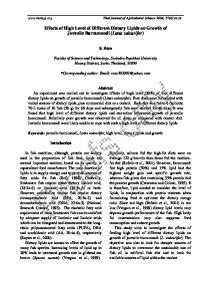
sorbance from ambient such as moisture and CO2. In certain cases, the spectrum before the plasma treatment was subtracted from the spectrum after the treatment. The obtained differential spectra reflected the difference in absorbance between the as-deposited and the plasma-damaged film and allowed us to analyze the small modifications that were not pronounced in normal spectra. Time-of-flight secondary-ion mass spectroscopy 共TOF-SIMS兲 was used to obtain the concentration profile of the film components. The data were obtained using an IONTOF IV instrument in a noninterlaced dual beam mode with a Xe sputtering beam and a bunched 15 keV Ga analysis beam to detect negative secondary ions. The Ga analysis beam was rastered over a 100 ⫻ 100 m area. The Xe sputtering beam was used with 1 keV of impact energy and 80 nA of current using a raster size of 500 ⫻ 500 m. Results Effect of power and time of He pretreatment.— Structural modification.— The reduction in the concentration of organic hydrophobic agents 共carbon depletion兲 is one of the measures of plasma damage. The depth of carbon depletion as measured by TOF-SIMS is shown in Fig. 1. The pure He plasma causes minimal C-depletion, while the NH3 plasma produces the highest C-depletion. The degree of C-depletion is strongly reduced by a He plasma treatment preceding the exposure to the NH3 plasma. This effect becomes more pronounced at higher rf power levels of He plasma pretreatment. The depth of the C-depletion is twice as low after the combined 1400 W He + NH3 plasma when compared with the pure NH3 plasma treatment. The bonding structure of the low-k material was studied by FTIR. The amount of Si–CH3 groups is expressed as a ratio of integrated absorbance of Si–O 共970–1260 cm−1兲 and Si–CH3 共1260–1290 cm−1兲 groups, as shown in Fig. 2. The reduction of Si–CH3 /Si–O ratio indicates the removal of Si–CH3 groups. The dotted line represents the Si–CH3 /Si–O ratio of the as-deposited film 共reference level兲. The removal of the Si–CH3 groups is observed after each plasma treatment, but the biggest C-depletion occurs after NH3 only and 400 W He + NH3 plasma treatments. FTIR data 共Fig. 2a兲 support previous conclusions based on TOF-SIMS results that the minimal C-depletion occurs in He plasma, and the degree of depletion is reduced by the combination of He and NH3 plasma treatments starting from a He rf power of 600 W. Figure 2b represents the Si–CH3 /Si–O ratio vs time of He plasma treatment. The Si–CH3 bond depletion is limited for combined He + NH3 plasma treatments and decreases with time of He pretreatment. For a constant time of 60 s, the higher power of He
Figure 1. Carbon depth profile of the as-deposited and plasma treated films as measured by TOF-SIMS.
Downloaded 08 Apr 2010 to 146.103.254.11. Redistribution subject to ECS license or copyright; see http://www.ecsdl.org/terms_use.jsp
Journal of The Electrochemical Society, 157 共5兲 H565-H573 共2010兲
H567
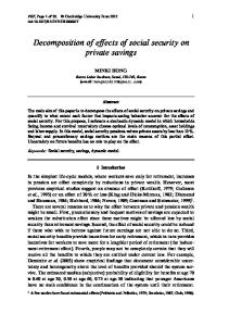
Figure 2. 共a兲 The ratio of integrated absorbance of Si–CH3 and Si–O 共as measured by FTIR兲 vs rf power of He pretreatment. 共b兲 The ratio of integrated absorbance of Si–CH3 and Si–O 共as measured by FTIR兲 vs time of He pretreatment.
pretreatment 共1400 W兲 results in a more effective reduction of the Si–CH3 bond depletion. Figure 3 shows open porosity as measured by the toluene-based EP. The pristine low-k film has 25% of open porosity. The open porosity increases slightly by 1–2% after the NH3 plasma treatment. On the contrary, the pure He plasma treatment reduces the open porosity by 3–4%. Increasing the rf power 共starting from 600 W兲 of 20 s He pretreatment inhibits the effect of porosity increase imposed by the NH3 plasma. However, we did not find any evidence of surface sealing effect. The adsorption and desorption isotherms followed the same trend, as in the pristine material. In contrast, longer exposure times 共40 and 60 s兲 of He plasma with a maximal power of 1400 W in the combined He + NH3 treatments caused the surface sealing effect, as shown in Fig. 4b and 5. The hysteresis loop between adsorption and desorption branches of the isotherms is related to a delay in the pore filling and emptying during the adsorption and desorption cycles 共Fig. 4b兲. The integral refractive index measured in vacuum increases slightly from 1.367 for a reference sample to 1.382 after the 60 s He + 15 s NH3 plasma treatment. This suggests that the total porosity changes insignificantly, and, therefore, the bulk of the film is still porous. Therefore, the diffusion limitation of the toluene penetration is only related to the densification of the top part of the film. Such “partial sealing” indicates a decrease in size of the pore necks at the surface. In this case, it is not possible to calculate the pore size distribution. We can only conclude that the effective pore size in the top part of the film becomes comparable with the size of toluene molecules, approximately 6 Å.
Figure 3. Open porosity 共as measured by EP兲 vs rf power of He pretreatment.
Quantification of the sealing efficiency can be based on the “delay” between the toluene adsorption and desorption branches /2 vs time of the plasma treatment. The /2 is the difference between the values of P/Po on the adsorption and desorption curves that correspond to the pore filling of 50%, as indicated by an arrow in Fig. 4b. In all these experiments, the rate of the pressure change was the same. Therefore, this delay reflects the change in the toluene diffusion rate through the top densified layer. A longer delay corresponds to a smaller size of the remaining pores. The /2 increases with the time of He plasma treatment, as shown in Fig. 5. Therefore, the degree of densification of the top densified layer depends on the
Figure 4. 共a兲 Toluene adsorption/desorption isotherms 共as measured by toluene-based EP兲 for as-deposited low-k film 共reference兲. 共b兲 Toluene adsorption/desorption isotherms 共as measured by toluene-based EP兲 for low-k films after 60 s of He plasma treatment and subsequent 60 s He + 15 s NH3 plasma treatment.
Figure 5. Delay between adsorption and desorption isotherms of toluene 共calculated from EP data兲 for different times of plasma treatment.
Downloaded 08 Apr 2010 to 146.103.254.11. Redistribution subject to ECS license or copyright; see http://www.ecsdl.org/terms_use.jsp
H568
Journal of The Electrochemical Society, 157 共5兲 H565-H573 共2010兲
Figure 6. The thickness loss as measured by visible 共VIS兲 共in the range 350 nm-780 nm兲 SE.
time of He plasma treatment. The porous low-k film after subsequent 60 s He and NH3 plasma treatment does not show any toluene adsorption 共Fig. 4b兲. This proves that the pore size approaches the toluene molecule size of 6 Å 共surface sealing effect兲. The surface sealing effects can also be studied using the EP system and analyzing a solvent filling time at the solvent SVP.14 The solvent penetration increases with the filling time dependent on the barrier integrity 共surface sealing efficiency兲.14,15 To study this, the fully sealed sample treated with 60 s He + 15 NH3 plasma was filled with toluene for approximately 3000 s. The toluene vapor pressure was increased from 0 to 24 Torr 共toluene SVP兲 in 2000 s. Next, a 1000 s sample was kept in a vacuum chamber at a toluene pressure of 24 Torr. After 1000 s, the change in refractive index was less than 0.003. This shows that after this time, the diffusivity of toluene through the densified layer was close to 0. The thickness loss after all plasma treatments was measured by SE 共Fig. 6兲. The thickness was extracted from the best fits of a Cauchy model, as discussed in the Metrology section. The NH3 plasma reduces the thickness of the low-k film by about 20 nm. On the contrary, the thickness loss for the pure He plasma treatment is smaller than 8 nm. The thickness loss after NH3 plasma is reduced in the He pretreatment with an rf power higher than 600 W. Hydrophobic properties.— Figure 7 shows the amount of adsorbed water measured by water EP for different 共a兲 rf powers and 共b兲 times of He plasma pretreatments. The dotted line represents the water adsorption in a pristine film 共1.6%兲. After 15 s of NH3 plasma treatment, the amount of adsorbed water increased up to 16%. Compar-
ing this value with the total open porosity 共24%兲, one can conclude that more than 50% of the film becomes hydrophilic. The pure He plasmas of 400 and 800 W almost do not change the hydrophilicity of the film bulk. Pretreatments in He plasmas reduce the degree of bulk hydrophilization imposed by the NH3 plasma. This reduction is proportional to the rf power of the 共a兲 He plasma and 共b兲 time of the plasma treatment. The treatment of the 1400 W He + NH3 plasma results in 5.5% of adsorbed water. The combined treatment of the 60 s He 1400 W + 15 s NH3 plasma results in hydrophilization of 1.6%, which is equal to the as-deposited sample 共Fig. 7b兲. The WCA of the as-deposited film is 95°. The reduction in the CAW is observed after all treatments. However, it was possible to distinguish two groups: only He plasma and all treatments containing NH3. For pure He, the WCA was higher than 20°. For all NH3-containing treatments, the WCA was lower than that after He plasma only. Therefore, contrary to the bulk properties, the low-k surface becomes hydrophilic after all the plasma treatments. Figure 8a shows the integrated absorbance of –OH groups 共3100–3800 cm−1兲 obtained by FTIR. The hydrophilization is proportional to the amplitude of the Si–OH absorbance band. The dotted line represents the reference data for the as-deposited film. The reference films reveal the –OH absorbance close to 0. He plasma treatment increases the –OH amount. This increase, however, is smaller than that for all NH3-containing treatments. The pure NH3 plasma treatment resulted in the highest –OH incorporation. The He pretreatment reduced –OH group incorporation imposed by the pure NH3 plasma. This reduction was proportional to the rf power of He plasma. The FTIR spectra of some samples in the spectral range of 600–4000 m−1 are shown in Fig. 8b. The investigated low-k is characterized by the Si–O–Si backbone 共1000–1200 cm−1兲, Si–CH3 共1274 cm−1兲, and Si–H 共2250 and 890 cm−1兲 bonds. The appearance of the absorbance of the Si–OH and H2O groups 共3900–3100 cm−1兲 depends on hydrophobic properties of the film. The intensities of the Si–CH3 and Si–H absorbences are decreased after plasma treatments, while the absorbencies of the Si–OH groups are increased. The decrease in Si–CH3 and Si–H bonds and the increase in Si–OH after He and combined He + NH3 plasmas are relatively small compared with the pure NH3 plasma chemistry. The absorbance of the Si–OH groups increases the most after NH3 due to the significant film hydrophilization and subsequent moisture absorption. Discussion The presented experimental data demonstrated that a pure NH3 plasma produces significant damage to the low-k material. Structural and chemical modification of the bulk of the low-k material is minimal in pure He plasmas. The He plasma pretreatment before exposure to NH3 plasma has beneficial effects, such as reduction in plasma damage and possibility of sealing of the low-k surface. The
Figure 7. 共a兲 The amount of adsorbed water 共as measured by water-based EP兲 of as-deposited He-plasma-treated and He + NH3-plasma-treated low-k films vs rf power during He plasma treatment. 共b兲 The amount of adsorbed water 共as measured by water-based EP兲 of asdeposited He-plasma-treated and He + NH3-plasma-treated low-k films vs treatment time.
Downloaded 08 Apr 2010 to 146.103.254.11. Redistribution subject to ECS license or copyright; see http://www.ecsdl.org/terms_use.jsp
Journal of The Electrochemical Society, 157 共5兲 H565-H573 共2010兲
H569
less stable Si–H groups and the breakage of Si–O–Si groups with a formation of hydrophilic silanol groups are thermodynamically favorable3 ⬅Si–CH3 + 2H → ⬅ Si–H + ↑CH4 共⌬Hr = − 411 kJ mol−1 at 298 K兲 ⬅Si–O–Si ⬅ + 2H → ⬅ Si–H + → ⬅ Si–OH共⌬Hr = − 325 kJ mol−1 at 298 K兲
Figure 8. 共Color online兲 共a兲 Integrated absorbance of OH groups as measured by FTIR vs rf power of He plasma pretreatment. 共b兲 IR absorption spectra of chosen low-k films in the range of 4000–400 cm−1 as measured by FTIR.
sealing efficiency depends on the time and power of He plasma pretreatment. In the following section, we analyze the nature of the observed phenomena. Effect of NH3 plasma.— The most important active components formed in NH3 plasma are NH2, N2H4, and H radicals. Hydrogen radicals play a key role in the Cu oxide reduction during the postCMP cleaning. However, all these radicals are chemically active with respect to SiOC:H-based low-k materials and result in their damage. The different effects of the NH3 plasma have already been discussed in addition to the papers reporting damage of the low-k materials.4,9,17,18 Peng et al.18 reported that NH3 plasma in certain conditions is able to seal the surface of the MSQ-based low-k film. We also showed in our previous work with different types of chemical vapor deposition 共CVD兲 low-k materials that pure NH3 plasma damages the low-k material, but the consecutive treatment by He and NH3 plasmas is able to reduce the plasma damage and seal the surface.9 The effect of H radicals on SiOC:H low-k films has been extensively studied and well documented3,4,19-24 because of the wide application of the hydrogen-based plasmas for the resist strip and postdry-etch cleaning. However, the H2-based plasmas cause many different effects. Some groups report that these plasmas have no effect on the SiOC:H film,4,19,20,22 others report that it enhances the dielectric properties,24 and yet others indicate that H2 plasmas cause significant damage.3,21 The replacement of CH3 groups by H atoms with a formation of
关1兴
Therefore, the H radicals are able to damage low-k dielectrics if they have sufficient activation energy required for Reaction 1. Indeed, detailed analysis of the available data shows that the ability of the H2-based plasma to break Si–CH3 bonds strongly depends on experimental conditions. According to our study, H radicals formed in downstream H2 and He/H2 plasma do not reduce the concentration of Si–CH3 groups in the temperature range from 20 to 350°C.23,24 This observation agrees well with the literature data, demonstrating no low-k damage in downstream H2, He/H2, and He/Ar plasmas.17,19,20 However, certain additional activation provided, for instance, by ion radiation and UV light makes these reactions possible, causing the difficulty to realize damage-free processes in the reactive ion etching 共RIE兲 condition.19,25 For instance, Matshushita et al.19 showed that the damage during the H2 plasma treatment depends on the type of chamber used. The processes were damagefree in the ion-free discharge. The effect of charged species from H-plasmas for cleaning in the pressure range of 200–400 mTorr was also discussed by Fu et al.26 The authors compared the H2 plasma effect on low-k with and without plasma leakage reduction 共PRL兲 hardware to reduce the plasma density. They found no Si–CH3 depletion only when the PRL hardware was used. Similar work and conclusions have also been presented by Lazzeri et al.22 The effect of N radicals has also been studied in the literature.17,27 Pure N2 plasma damages only the top surface of low-k materials and makes it hydrophilic. Some nitrogen incorporation and reduction of a Si–CH3 group in the surface area has also been observed. Our study based on FTIR analysis confirms these observations.24 The low-k film treated with the downstream N2 plasma shows a small Si–CH3 bond reduction and a decrease in the water surface contact angle from 95 to 60°. The ability of nitrogen radicals to change surface energy plays a positive role in post-CMP cleaning. The presence of nitrogen radicals remarkably improves the adhesion force of a cleaned stack with the deposited dielectric liner.28 However, the presence of nitrogen 共for instance, in N2 /H2 plasma兲 initiates the damage of low-k material by hydrogen radicals.4,17,23 Effect of NHx radicals.— One possibility how the NH3 plasma leads to the film hydrophilization is the replacement of Si–CH3 bonds by Si–NH2, which are in turn replaced by Si–OH.17 The chemical interaction is represented by the following equations ⬅Si–CH3 + NH2 + H → ⬅ Si–NH2 + CH4 ↑ ⬅Si–NH2 + H2O → ⬅ Si–OH + NH3
关2兴
Hydrolysis of ⬅Si–NH2 groups was proposed by Posseme et al.17 Using in situ and ex situ X-ray photoemission spectroscopy analyses, they showed that the nitrogen content in low-k films treated in NH3-RIE plasma has been strongly reduced after air exposure, and the surface became hydrophilic. An additional proof of possibility of hydrolysis is the value of the enthalpy of reaction, ⌬Hr = −258 kJ mol−1 at 298 K. This explains the carbon depletion 共Fig. 1兲 and the film hydrophilization 共Fig. 7 and 8兲. The Si–NH2 groups on the silica surface might also be formed by the reaction of NH3 molecules with “highly strained” or ionic siloxane bridges.29,30 The reaction is represented by the equation
Downloaded 08 Apr 2010 to 146.103.254.11. Redistribution subject to ECS license or copyright; see http://www.ecsdl.org/terms_use.jsp
H570
Journal of The Electrochemical Society, 157 共5兲 H565-H573 共2010兲 Si–O–Si␣⬍144° + NH3 → Si–NH2 + SiOH
关3兴
It is also important to analyze the role of NHx radicals in structural changes occurring in low-k dielectrics. We simulated IR Si–O–Si absorbance after the NH3 plasma exposure.31 The band related to CH3 groups shifts to the lower frequencies, which is also evidence of a strong increase in the -bonding contribution in the Si–O–Si system. Because an increase in the -bonding causes an increase in the Si–O–Si angle, a pore of 1 nm in radius can increase by 0.4–0.5 Å 共that is, by about 2%兲. This calculation supports the experimental data. We observed an increase in the porosity after the NH3 plasma treatment of about 1–2% and also a small increase in the pore size. The increased pore size might be also due to the removal of porogen residues by NH3 plasma 共amorphous carbon and cyclic hydrocarbons兲 embedded in the low-k matrix. The porogen residues are generated during the UV curing step of the PECVD low-k material. The porogen residues might actively react with the NH3 plasma radicals and be removed from the low-k matrix, which results in the increased pore size.32 Effect of He plasma.— In our previous work,9 we speculated that the major modifications caused by He plasma are due to the energy transfer from EUV photons 共He has intense spectral lines below 60 nm兲 and 21S He metastable atoms33 to the low-k structure. The effect of the ion bombardment in a He plasma is not significant because the wafer is placed on the grounded electrode 共only self-bias is applied to He ions兲, and, moreover, the mass of He atoms is relatively small. The modification of SiO2 layers caused by EUV radiation from He plasma has been reported.34,35 EUV light is able to break Si–O bonds on the SiO2 surface and form so-called “E⬘ defects” 共oxygen vacancies兲. Using the absorption coefficients reported by Philipp,36 one can calculate the penetration depth of EUV photons from He plasma into the silica. These calculations show that the intensity of EUV light with wavelengths of 60–100 nm decreases to 1/e within the first 10 nm of silica. Therefore, most photochemical modifications of a silica-based low-k film should be restricted to 10–20 nm of the top layer. A more detailed study of the modified layer can be found in our previous work.9 We also consider the effect of He metastable atoms on the low-k surface. They were reported to cause damage to the porous silica.37 The typical energies of metastable He atoms are 19.82 eV 共23S state兲 and 20.62 eV 共2 1S state兲,38 which are close to the energies of EUV photons. The high energy metastable atoms could create electron–hole pairs in the film.38 The holes trapped at the low-k film surface form fixed positive charges. The positive charge leads to the Si–O and Si–C bonds scission. The effect of metastable atoms is reported to be localized in the top 1–2 nm of the film.37 The defects formed by EUV light and metastable atoms are chemically active and could result in the formation of surface active centers localizing the chemical reactions to the surface. The oxygen vacancies are centers for the chemisorption of active radicals. Another important factor of He plasma pretreatment is a decrease in the size of pore necks. It is less clear how the He + NH3 plasma treatment reduces the pore neck size. It was speculated31 that a rupture of a proton from a CH3 group also occurs when exposed to He plasma, resulting in a shift of the Si–O–Si bond angles distribution toward larger angles. A subsequent treatment of the film in the NH3 plasma, after He, promotes cross-linking over these −CHx groups, as well as Si atoms; −NHx may serve as a bridge. As a result, the pore size decreases, or the pores get sealed, because the reaction proceeds at the very pore entrance. Because of this, if porosity is measured on the basis of the refractive index, one would not see any essential changes. The number of built-in NH2 groups may be small because building-in occurs only at the surface; this may be why these groups do not manifest themselves in the IR spectra. Another factor that might influence the plasma damage reduction is the surface roughening induced by He plasma. The effect of the
different He rf power levels on the low-k surface roughness was studied by Yanai et. al.8 They found, using atomic force microscopy, that the mean surface roughness 共MSR兲 was in the range of 0.18– 0.39 nm. The as-deposited film showed an MSR of 0.39 nm. With irradiation with He plasma at 100 W, the surface became smoother 共MSR = 0.18 nm兲; when the plasma power was increased to 500 W 共MSR = 0.31 nm兲, the surface became rougher. Yanai et al.8 presumed that the rougher surface is due to surface carbon depletion at the first monolayer. No correlation between the surface roughness and the damage reduction effect of He plasma was found. The main effect on damage reduction was related to the densified surface by EUV radiation from He plasma. This corresponds with our conclusion that the reduced mean pore size in 10–20 nm of the modified film layer is the most important factor to reduce the depth of radical penetration and therefore the depth of the plasma damage. The mean travel distance of the chemically active radical is significantly reduced due to multiple collisions on narrow pore necks. The multiple collisions significantly increase the probability of recombination or chemisorption of active radicals. Let us analyze the conclusions stated above on the basis of the Knudsen diffusion mechanism39 and random walk theory.40 In our case, the plasma species 共radicals and molecules兲 undergo Knudsen diffusion, traveling into the low-k matrix because a mean free path length of species in the NH3 plasma is a few orders of magnitude larger than the pore size.39 For instance, assuming a particle size of 2 Å, the mean free path length is approximately 43 m at 20°C at 530 Pa, while the pore size is approximately 2 nm. The Knudsen diffusion mechanism implies that there are no collisions between the particles in the gas phase. We consider the Knudsen diffusion mechanism for further discussion of a plasma damage model. However, from the viewpoint of the plasma damage, only chemically active species with low-k film are important 共such as NHx radicals兲. To find how the depth of the plasma damage depends on pore size and recombination of active radicals on pore walls, we used the random walk theory formalism.40 The random walk theory implies that the root-mean-square distance from the origin after a random walk of N steps with length L is L冑N. So, let us assume that active radicals execute a random walk in the low-k skeleton, that in the Nth step, active radicals elastically collide with the pore wall and 共i兲 shift an average of 1.5 times of the pore diameter size L = 1.5d or 共ii兲 annihilate on the pore wall. The active radical annihilation occurs as a result of its recombination on the pore wall with probability ␥rec 共i.e., exothermic recombination with another radical on the pore wall; the radical becomes neutral molecule兲 or chemical reaction with the low-k skeleton with probability ␥chem, as described in a previous section. Therefore, the total probability of the radical annihilation 共total recombination coefficient兲 is ␥ = ␥rec + ␥chem. To clarify the link between step number N and ␥, let us take three hypothetical recombination coefficients 共␥兲 of NH3 on the low-k pore surface equal to 2 ⫻ 10−3, 2 ⫻ 10−2, and 10−2. In this case, the complete radical recombination on the pore walls occurs after 500, 100, and 50 collisions/steps 共N兲. Therefore, ␥ is inversely proportional to N. All the discussions above lead us finally to Eq. 4, combining main factors influencing the plasma damage depth 共 Pd兲 Pd = ad
冑
1 ␥rec + ␥chem
关4兴
According to the proposed model, there are four main factors influencing the Pd. Two factors are related to the pore geometry 共a coefficient兲 共i.e., tortuosity兲 and the pore size 共d兲. Both influence the mean travel distance L = a ⫻ d 共a = 1.5兲 of the chemically active radical. Two other factors are related to the neutralization efficiency of chemically active radicals. The first one is the probability of radical loss in a chemical reaction with the low-k matrix 共␥chem兲. The second one is the radical recombination 共␥rec兲 that leads to subsequent creation of the chemically neutral molecule. The recombination coefficients ␥rec of N and H radicals on the silica surface at
Downloaded 08 Apr 2010 to 146.103.254.11. Redistribution subject to ECS license or copyright; see http://www.ecsdl.org/terms_use.jsp
Journal of The Electrochemical Society, 157 共5兲 H565-H573 共2010兲
H571
Figure 9. Pds 共for different ␥兲 vs mean pore size of the low-k film. Presented data are achieved using Eq. 4, assuming ␥ = ␥rec + ␥chem and a = 1.5.
350°C are around 1.0 ⫻ 10−4, as reported.41 The total recombination coefficient 共i.e., reaction of O radicals with Si–CH3 groups or recombination on the Si–O low-k skeleton兲 of active radicals on the ELK HM low-k surface has also been studied42 for O radicals and is 6.0 ⫻ 10−3; and for H radicals, it is 0.22 ⫻ 10−3 at 20°C. The literature study shows that ␥chem has more impact on plasma damage reduction. Figure 9 shows the Pds for different ␥ plotted using Eq. 4. The Pd increases when 共i兲 the pore diameter is larger and 共ii兲 the recombination of chemically active radicals on the pore wall is higher. This explains the severe damage during the NH3 plasma treatment. The pore radius is increased, as discussed in a previous section, and results in increased penetration of the chemically active radicals into low-k. The He pretreatment decreases the pore radii and increases the reactivity of NHx species with low-k film. So, the plasma damage is significantly reduced. Mechanisms of thickness loss of low-k treated in NH3, He, and sequential He ⫹ NH3 plasmas.— The mechanism of thickness loss in processing plasmas at elevated wafer temperatures 共350°C兲 can be caused by chemical 共reactive plasma radicals兲 and physical plasma effects 共UV radiation and hot electrons兲.43 Higher thickness loss in the pure NH3 plasma than in He plasma 共Fig. 6兲 suggests that the chemical effect is domineering. The bond breakage caused by NHx radicals from the NH3 plasma occurs within the SiCOH matrix that results in the formation of activated silyl sites. The activated silyl sites are then available to react with other activated silyl species to form Si-Si crosslinks or possibly with SiOH to generate a SiOSi crosslink. 21 The chemical-assisted cross-linkage results in the film thickness loss. The thickness loss in the pure He plasma is much smaller because only the UV and electron-beam and He metastable atoms interact with the film. The effect of UV and metastable atoms is limited to the surface. In the combined He + NH3 treatment, the thickness loss is prevented due to the reduced penetration depth of NH3 plasma radicals, which reduces the effect of the chemical-assisted cross-linking. The thickness loss can also be due to the etching of the dielectric in the studied plasmas. It was proposed by Worsley et al.3 that the total depth of ash plasma damage is the sum of etch depth and the modification depth. They studied the reducing Ar/H2 ash plasma in the CCP-type plasma chamber at room temperature, where samples were placed on a biased electrode. Worsley et al.3 showed that the etch depth increases with the porosity of low-k film and the physical sputtering element of etching 共ion bombardment兲. In our case, how-
Figure 10. Absorbance and differentiated absorbance for He and NH3 plasma treatments as measured by FTIR.
ever, the ion bombardment effect is minimal because films were placed on the grounded electrode. The only possibility to induce film etching would be volatilization of the Si-containing reaction products due to increased temperature of the substrate 共350°C兲. However, only a small fraction of the thickness loss might be due to etching because the reactivity of the NH3 plasma chemistry with Si–O bonds is very low. Therefore, most of the thickness loss is due to the effect of chemical-assisted cross-linking, as described in the previous paragraph. Suboxide as a sign of active centers formation.— The peak around 1000 cm−1 indicates suboxide or strained ring formation in SiO2-based materials.44,45 In this section, we discuss the IR absorbance at 1000 cm−1 after studying plasma treatments using the differential FTIR spectroscopy. We presume that the evolution of the 1000 cm−1 peak might explain the damage reduction mechanism in the combined He + NH3 treatment. We propose two possible explanations based on the differential FTIR spectroscopy measurements. The first is that the suboxide appearance after He plasma treatment might indicate an oxygen vacancy formation. The oxygen vacancy might serve as a recombination center for NH3 plasma radicals. The second possibility is that the NH3 plasma radicals might react with strained rings, which are mainly formed on the top surface of low-k after He plasma treatment 共see Eq. 3兲. Therefore, fewer radicals penetrate the bulk of the low-k material. The strained rings play a major role in chemical reactivity and defect formation in porous SiO2-based materials.45,46 Figure 10 shows FTIR spectra of low-k film before and after exposure to the various plasmas. The top graph of the figure shows FTIR spectra of the as-deposited and the NH3-plasma-treated sample in the range of 800–1300 cm−1. The FTIR spectra typical of SiOC:H-type materials contain an absorption band related to the Si–O–Si network 共1040–1070 cm−1兲, a shoulder of a cagelike struca suboxide absorption band ture 共1100–1150 cm−1兲, 共1000–1030 cm−1兲, and an absorption band related to Si–CH3 bonds 共1250–1300 cm−1兲. The SiOC:H film contains bonds local-
Downloaded 08 Apr 2010 to 146.103.254.11. Redistribution subject to ECS license or copyright; see http://www.ecsdl.org/terms_use.jsp
Journal of The Electrochemical Society, 157 共5兲 H565-H573 共2010兲
H572
might react with strained rings formed after He plasma exposure, and this limits their penetration into the bulk of the low-k material 共see Eq. 3兲. Conclusions
Figure 11. Integrated amplitude of the suboxide peak vs plasma conditions. Arrows indicate the effect of the NH3 treatment.
ized at 1200 − 1000 cm−1 from C–O–C or Si–O–C asymmetric stretching vibrations.21 However, the identification is difficult because they overlap with the Si–O–Si asymmetric stretching band. After the NH3 plasma treatment, a clear shift to higher wavenumbers of the Si–O–Si absorption band is observed. This shift is also reflected in the differential spectrum 共bottom graph兲. However, the characteristic changes are much smaller after He plasmas due to the small thickness of the modified layer of 10–20 nm 共around 10% of the film thickness兲. Therefore, we used the differential FTIR to study the changes after successive exposure in He and NH3 plasmas, as shown in Fig. 10 共bottom graph兲. The change in absorbance at 1275 cm−1 arises from Si–CH3 groups47 and decreases the most after the NH3 plasma treatment. The peaks of the differential spectra related to Si–O–Si have been reported.44 The negative peak located close to 1150 cm−1 is related to the Si–O–Si 共angle ⬃150°兲 cagelike structure. The positive peak around 1070 cm−1 共angle ⬃144°兲 is related to the Si– O–Si network. The highest positive maximum of the network peak appears after pure NH3 plasma. The peak around 1000 cm−1 arises from the Si–O–Si suboxide 共angle ⬍144°兲. This peak appears after He plasma treatment. The amplitude of this peak increases with the time of plasma treatment. The smallest amplitude appears after the successive exposure to He 共60 s兲 and NH3 共15 s兲 plasmas. To evaluate the effect of the plasma treatment, the amount of suboxide was estimated by the integration of differentiated absorbance using Eq. 5
Ai =
冕
k=970 cm−1
A共k兲dk
关5兴
k=1030 cm−1
where Ai is the integer of differentiated absorbance and k is the wavenumber. The obtained results are shown in Fig. 11. One can see that the suboxide is always formed when the pure He plasma is applied 共empty symbols兲. Moreover, the amount of suboxide grows with time and power of He plasma treatment. The suboxide peak disappears when the NH3 plasma treatment is applied 共as indicated by the arrows兲. The only exception is the 60 s He + 15 s NH3 plasma treatment when the suboxide peak is still positive, and the film is fully sealed. Finally, the appearance of the suboxide peak is most probably related to the formation of oxygen vacancies in the low-k film, as was discussed in the previous section. The suboxide peak disappears after their saturation by active radicals 共NH2, H, etc.兲 from the ammonium plasma. Another possibility is that the NH3 plasma radicals
The effect of the combined He and NH3 plasma treatments on a CVD SiOC:H low-k dielectric is evaluated. The pure NH3 plasma has a detrimental effect on the low-k material. The NH3 plasma treatment leads to bulk hydrophilization of the low-k material. He plasma causes surface modification without damaging the bulk of the low-k. The major modifications caused by He plasma are due to energy transfer from EUV photons and 21S He metastable atoms to the low-k structure. The defects formed by EUV light and metastable atoms are oxygen vacancies formed due to the breaking of Si–O bonds, and they are localized in the thin top layer. Oxygen vacancies are centers for chemisorption of active radicals. The mechanism of plasma damage reduction in the subsequent He + NH3 plasma treatment is explained on the basis of the Knudsen diffusion mechanism and random walk theory. The defects in low-k structure generated during He plasma treatment traps chemically active radicals on the pore walls. Moreover, He plasma pretreatment decreases the size of pore necks on the surface, which increases the collision frequency of chemically active radicals with the pore walls. The increased collision frequency increases the chance of radical recombination or chemisorption at the first surface monolayers. As a result, He plasma pretreatment makes the low-k material more resistant to the subsequent treatment in the NH3 plasma. The plasma damage reduction is proportional to He plasma density, which is proportional to rf power during He plasma exposure. Furthermore, the low-k surface is sealed if the He pretreatment exceeds a critical level. The analysis of available literature data suggests that the threshold for plasma sealing in NH3 and combined He + NH3 plasmas depends on the type of low-k material and chamber used for the plasma treatment. A possible nature of the sealing capability of NH3 plasmas might be related to the promoted crosslinking over the −CHx groups formed in He plasma where −NHx may serve as a bridge. Differential FTIR spectroscopy might be used to monitor the pore sealing efficiency in the combined He + NH3 plasma treatment. The amplitude of absorbance around 1000 cm−1 grows with time and power of He plasma treatment. Subsequent NH3 plasma treatment reduces the 1000 cm−1 absorbance. The only exception when the differential 1000 cm−1 peak is still positive is when the porous low-k film is fully sealed after the combined He + NH3 plasma treatment. Acknowledgments We acknowledge D. De Roest and H. Sprey, ASM, Belgium for useful discussions and support. A.M.U. acknowledges S. Eslava and C. Huffman for their practical and scientific help. IMEC assisted in meeting the publication costs of this article.
References 1. K. Maex, M. R. Baklanov, D. Shamiryan, F. Iacopi, S. H. Brongersma, and Z. S. Yanovitskaya, J. Appl. Phys., 93, 8793 共2003兲. 2. M. R. Baklanov, A. M. Urbanowicz, G. Mannaert, and S. Vanhaelemeersch, in International Conference on Solid-State and Integrated Circuit Technology, Chinese Institute of Electronics, p. 291 共2006兲. 3. M. A. Worsley, S. F. Bent, S. M. Gates, N. C. M. Fuller, W. Volksen, M. Steen, and T. Dalton, J. Vac. Sci. Technol. B, 23, 395 共2005兲. 4. A. M. Urbanowicz, A. Humbert, G. Mannaert, Z. Tokei, and M. Baklanov, Solid State Phenom., 134, 317 共2008兲. 5. Y. Travaly, J. Van Aelst, V. Truffert, P. Verdonck, T. Dupont, E. Camerotto, O. Richard, H. Bender, C. Kroes, D. De Roest, et al., in International Interconnect Technology Conference, IEEE Electron Devices Society, p. 52 共2008兲. 6. A. Humbert, L. Mage, C. Goldberg, K. Junker, L. Proenca, and J. B. Lhuillier, Microelectron. Eng., 82, 399 共2005兲. 7. Y. H. Wang, D. Gui, R. Kumar, and P. D. Foo, Electrochem. Solid-State Lett., 6, F1 共2003兲. 8. K. Yanai, T. Hasebe, K. Sumiya, S. Oguni, and K. Koga, MRS Bull., 863, B2.3 共2005兲. 9. A. M. Urbanowicz, M. R. Baklanov, J. Heijlen, Y. Travaly, and A. Cockburn,
Downloaded 08 Apr 2010 to 146.103.254.11. Redistribution subject to ECS license or copyright; see http://www.ecsdl.org/terms_use.jsp
Journal of The Electrochemical Society, 157 共5兲 H565-H573 共2010兲 Electrochem. Solid-State Lett., 10, G76 共2007兲. 10. P. Verdonck, D. De Roest, S. Kaneko, R. Caluwaerts, N. Tsuji, K. Matsushita, N. Kemeling, Y. Travaly, H. Sprey, M. Schaekers, et al., Surf. Coat. Technol., 201, 9264 共2007兲. 11. M. R. Baklanov, K. P. Mogilnikov, V. G. Polovinkin, and F. N. Dultsev, J. Vac. Sci. Technol. B, 18, 1385 共2000兲. 12. M. R. Baklanov and K. P. Mogilnikov, Microelectron. Eng., 64, 335 共2002兲. 13. D. Shamiryan, M. R. Baklanov, and K. Maex, J. Vac. Sci. Technol. B, 21, 220 共2003兲. 14. W. Puyrenier, V. Rouessac, L. Broussous, D. Rebiscoul, and A. Ayral, Microporous Mesoporous Mater., 106, 40 共2007兲. 15. D. Rebiscoul, L. Broussous, W. Puyrenier, V. Rouessac, and A. Ayral, J. Phys.: Conf. Ser., 152, 012002 共2009兲. 16. M. R. Baklanov, K. P. Mogilnikov, and T. Q. Le, Microelectron. Eng., 83, 2287 共2006兲. 17. N. Posseme, T. Chevolleau, T. David, M. Darnon, O. Louveau, and O. Joubert, J. Vac. Sci. Technol. B, 25, 1928 共2007兲. 18. H. G. Peng, D. Z. Chi, W. D. Wang, J. H. Li, K. Y. Zeng, R. S. Vallery, W. E. Frieze, M. A. Skalsey, D. W. Gidley, and A. F. Yee, J. Electrochem. Soc., 154, G85 共2007兲. 19. A. Matshushita, N. Ohashi, K. Inukai, H. J. Shin, S. Sone, K. Sudou, K. Misawa, I. Matsumoto, and N. Kobayashi, in International Interconnect Technology Conference, IEEE Electron Devices Society, p. 147 共2003兲. 20. I. L. Berry, Q. Han, C. Waldfried, O. Escorcia, and A. Becknell, in Semiconductor Equipment and Materials International: Technical Symposium: Innovations in Semiconductor Manufacturing, Semiconductor Equipment and Materials International 共2004兲. 21. A. Grill, V. Sternhagen, D. Neumayer, and V. Patel, J. Appl. Phys., 98, 074502 共2005兲. 22. P. Lazzeri, G. J. Stueber, G. S. Oehrlein, R. McGowan, and E. Busch, J. Vac. Sci. Technol. B, 24, 2695 共2006兲. 23. A. M. Urbanowicz, D. Shamiryan, P. Marsik, Y. Travaly, A. Jonas, P. Verdonck, K. Vanstreels, A. Ferchichi, D. De Roest, H. Sprey, K. Matshushita, S. Kaneko, N. Tsuji, S. Luo, O. Escorcia, I. L. Berry, C. Waldfried, S. De Gendt, and M. R. Baklanov, in Advanced Methalization Conference, UC Berkley, p. 594, San Diego 共2009兲. 24. A. Urbanowicz, D. Shamiryan, B. Chen, P. Verdonck, and M. Baklanov, Characterization of Low-k Dielectric Damage during Downstream Plasma Strip at Elevated Temperature, IMEC, Leuven 共2008兲. 25. I. L. Berry, Q. Han, C. Waldfried, O. Escorcia, and A. Becknell, in SEMI Technical Symposium: Innovations in Semiconductor Manufacturing, SEMICON WEST
H573
共2004兲. 26. X. Fu, J. Forester, J. Yu, P. Gopalraja, S. Ahn, A. Demos, and P. Ho, IEEE, 51 共2006兲. 27. S. L. Xu, C. Qin, L. Diao, D. Gilbert, L. Hou, A. Wiesnoski, E. Busch, R. McGowan, B. White, and F. Weber, J. Vac. Sci. Technol. B, 25, 156 共2007兲. 28. P. Verdonck, Influence of Reductive Plasmas on Adhesion of Dielectric Liner with Cleaned Stacks, IMEC, Leuven 共2008兲. 29. J. B. Peri, J. Phys. Chem., 70, 2937 共1966兲. 30. G. A. Blomfield and L. H. Little, Can. J. Chem., 51, 1771 共1973兲. 31. F. N. Dultsev, A. M. Urbanowicz, and M. R. Baklanov, in Material Research Society Proceedings, Material Research Society 共2008兲. 32. A. M. Urbanowicz, K. Vanstreels, D. Shamiryan, S. De Gendt, and M. Baklanov, Electrochem. Solid-State Lett., 12, H292 共2009兲. 33. R. S. Van Dyck, H. A. Shugart, and C. E. Johnson, Phys. Rev. A, 5, 991 共1972兲. 34. K. Yokogawa, Y. Yajima, T. Mizutani, S. Nishimatsu, and K. Suzuki, Jpn. J. Appl. Phys., Part 1, 29, 2265 共1990兲. 35. T. Tatsumi, S. Fukuda, and S. Kadomura, Jpn. J. Appl. Phys., Part 1, 33, 2175 共1994兲. 36. H. R. Philipp, in Handbook of Optical Constants of Solids, E. D. Palik, Editor, p. 749, Academic, Orlando 共1985兲. 37. K. Kurihara, T. Ono, K. Kohmura, H. Tanaka, N. Fujii, N. Hata, and T. Kikkawa, J. Appl. Phys., 101, 113301 共2007兲. 38. T. Ono, N. Itabashi, I. Ochiai, S. Yamamoto, and K. Mochiji, Jpn. J. Appl. Phys., Part 1, 36, 6718 共1997兲. 39. C. K. Ho and S. W. Webb, Gas Transport in Porous Media, pp. 12–13, Springer, Berlin 共2006兲. 40. G. H. Weiss, Aspects and Applications of The Random Walk, pp. 1–5, NorthHolland, Amsterdam 共1994兲. 41. Y. C. Kim and M. Boudart, Langmuir, 7, 2999 共1991兲. 42. O. V. Braginsky, A. S. Kovalev, D. V. Lopaev, E. M. Malykhin, T. V. Rakhimova, A. N. Vasilieva, S. M. Zyryanov, and M. R. Baklanov, IEEE Trans. Plasma Sci. 37, 1697 共2009兲. 43. V. Jousseaume, A. Zenasni, L. Favennec, G. Gerbaud, M. Bardet, J. P. Simon, and A. Humbert, J. Electrochem. Soc., 154, G103 共2007兲. 44. A. Grill and D. A. Neumayer, J. Appl. Phys., 94, 6697 共2003兲. 45. D. R. Hamann, Phys. Rev. B, 55, 14784 共1997兲. 46. H. Hosono, Y. Ikuta, T. Kinoshita, K. Kajihara, and M. Hirano, Phys. Rev. Lett., 87, 175501 共2001兲. 47. T. R. Crompton, The Chemistry of Organic Silicon Compound, p. 416, John Wiley & Sons, New York 共1989兲.
Downloaded 08 Apr 2010 to 146.103.254.11. Redistribution subject to ECS license or copyright; see http://www.ecsdl.org/terms_use.jsp