Effects of various plasma pretreatments on 193 nm photoresist and linewidth roughness after etching Myeong-Cheol Kima兲 Process Development Team, Semiconductor R&D Center, Samsung Electronics, San No. 24 Nongseo-Ri, Giheung-Eup, Yongin City, Gyeonggi-Do 446-711, Korea
Denis Shamiryan Silicon Process and Device Technology Division, IMEC vzw, Kapeldreef 75, B-3001 Leuven, Belgium
Youngjae Jung Process Development Team, Semiconductor R&D Center, Samsung Electronics, San No. 24 Nongseo-Ri, Giheung-Eup, Yongin City, Gyeonggi-Do 446-711, Korea
Werner Boullart Silicon Process and Device Technology Division, IMEC vzw, Kapeldreef 75, B-3001 Leuven, Belgium
Chang-Jin Kang and Han-Ku Cho Process Development Team, Semiconductor R&D Center, Samsung Electronics, San No. 24 Nongseo-Ri, Giheung-Eup, Yongin City, Gyeonggi-Do 446-711, Korea
共Received 9 December 2005; accepted 27 September 2006; published 3 November 2006兲 Among the pretreatment methods which are performed just after the lithographic process to minimize the roughness increase of 193 nm photoresist during the subsequent etching processes, an in situ plasma pretreatment is the most cost effective. A HBr plasma pretreatment has proven quite effective and a few papers have described the mechanism. In an effort to understand further, the authors evaluated four plasma pretreatments using HBr, Ar, H2, or Cl2 gases and compared their results. Fourier transform infrared 共FTIR兲 spectroscopy was performed for the investigation of the chemical changes effected by the plasma pretreatments. Cross-section scanning electron microscope 共SEM兲 images were used to measure the photoresist film thickness, while top-down SEM images and an off-line program were used to determine linewidth roughness 共LWR兲 changes for 70 and 80 nm line features. They found two different types of roughness. The first type is a low-frequency roughness, which repeats about every 400 nm and increases the LWR value substantially. The second type is a high-frequency roughness, which appears about every 100 nm and causes a moderate increase in the LWR value. From the top-down SEM images, they recognize that the low-frequency roughness is caused by collapse of the 193 nm photoresist during the following bottom antireflective coating and hard-mask etching processes. The no plasma and the Ar plasma pretreated samples show this low-frequency roughness and produce the worst LWR values of about 11 nm at the 70 nm linewidth features after ashing processes. The HBr and the H2 plasma pretreated samples, which mainly show the high-frequency roughness, result in the best LWR values of about 6 nm at the 70 nm linewidth features after ashing processes. The FTIR analysis shows that both the HBr and H2 plasma pretreatments reduce the CO content substantially, down to about 20%–40% of the original CO content of the 193 nm photoresist as-coated film. On the other hand, the Ar plasma pretreated photoresist film still has about 60% of the CO content of the pristine 193 nm photoresist. The authors conclude that the low-frequency roughness has a critical relationship with the CO content in the 193 nm photoresist. They also find that the elements being incorporated into the 193 nm photoresist during the plasma pretreatment are important for their impact on the LWR. Especially, the Cl2 plasma pretreatment, which eliminates about the same amount of the original CO content in the photoresist as both the HBr and H2 plasma pretreatments, deteriorates the LWR notably just after the pretreatment and produces the most severe deformation after etching processes. Of the plasma pretreatments evaluated in this work, the HBr plasma pretreatment is the best in view of both the LWR and the application. The H2 plasma pretreatment, which shows the same lowest LWR value as the HBr plasma pretreatment, reduces the photoresist thickness substantially. However, even the HBr plasma pretreatment has one critical disadvantage because it generates the high-frequency type of roughness, which is not found in the case of the inert Ar plasma pretreatment. The H and Br radicals react with the 193 nm photoresist during the HBr pretreatment and appear to cause some side reactions and generate the high-frequency type of roughness during subsequent plasma processes. To minimize both the low- and high-frequency deformations simultaneously, we propose an inert gas plasma pretreatment process of which process parameters such as pressure and power are optimized to reduce the CO content of the 193 nm photoresist less than 40% of the original CO content as coated. © 2006 American Vacuum 2645
J. Vac. Sci. Technol. B 24„6…, Nov/Dec 2006
1071-1023/2006/24„6…/2645/8/$23.00
©2006 American Vacuum Society
2645
2646
Kim et al.: Effects of various plasma pretreatments on 193 nm photoresist
2646
Society. 关DOI: 10.1116/1.2366616兴
I. INTRODUCTION Currently, 193-nm-based lithography is replacing the 248-nm-based lithography in the manufacturing of semiconductor devices in sub-100-nm nodes.1,2 However, from the beginning of development, the 193 nm photoresist has shown poor etching resistance.3 The traditional Ohnishi parameter, which says that the oxygen atoms in the photoresist increase the etching rate of the photoresist, could explain the low etching resistance of the 193 nm photoresist, because it contains a substantial amount of carbonyl groups.4–6 Furthermore, the carbonyl groups contained in 193 nm photoresist, which are absent in the previous 248 nm photoresist, have been found to generate unique types of surface roughness during plasma etching.7–9 Ling et al. verified that the ionenhanced selective volatilization of the carbonyl groups of 193 nm photoresist accompanies plasma etching and causes severe surface roughness.8 To reduce the plasma etching induced roughness, Ling et al. proposed preliminary elimination of the carbonyl groups through the design of photoresist or pretreatments such as electron beam.8 These intrinsic material instabilities of the 193 nm photoresist with plasma etching processing will persist even in the next lithographic immersion technology of the 193 nm photoresist, which is based on the same material matrix as the present dry 193 nm lithographic technology.10 The line edge roughness 共LER兲 or the linewidth roughness 共LWR兲 has clearly been shown to substantially deteriorate the electrical performance of metaloxide-semiconductor transistors.11–13 Therefore, decreasing the roughness of the 193 nm photoresist generated during plasma etching is a worthwhile pursuit. For reducing the plasma induced deformation of 193 nm photoresist, this article deals with a plasma treatment which is performed after a lithographic process but before plasma etching processes. This in situ plasma pretreatment method is worth studying from the cost perspective. However, some negative side effects are expected for this additional plasma pretreatment method because the electron and ion energies and the UV wavelengths are much more dispersive than those of other comparable pretreatments such as e-beam and UV curing methods. Furthermore, the elemental components of the plasma pretreatment process may incorporate into the photoresist and create issues during the following etching processes. Recently, the HBr plasma pretreatment was proven very effective on reducing the 193 nm photoresist deformation caused by plasma etching, and the mechanisms were explained in depth.14,15 To understand further what makes the HBr plasma pretreatment the most effective and hopefully to find other promising plasma pretreatments, we evaluated four plasma processes using the HBr, Ar, H2, or Cl2 gases and compared their results. The subsequent etching conditions for bottom antireflective coating 共BARC兲 and a兲
Electronic mail:
[email protected]
J. Vac. Sci. Technol. B, Vol. 24, No. 6, Nov/Dec 2006
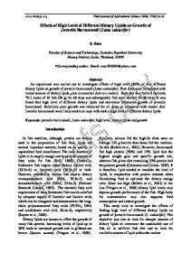
hard-mask SiO2 layers were evaluated and chosen to deteriorate line roughness significantly and to reveal the different effects of each plasma pretreatment on the LWR value quantitatively. We performed the Fourier transform infrared 共FTIR兲 spectroscopy to understand the chemical changes resulting from the plasma pretreatments. We used the scanning electron microscope 共SEM兲 to determine the photoresist thickness, LWR, and LER changes. The effects of the CO content and incorporated elements in the 193 nm photoresist on the LWR after etching are discussed and the requirements of the most promising plasma pretreatment are proposed. II. EXPERIMENT A commercial inductively coupled plasma etching chamber, the 2300 Versys® silicon of Lam Research Corporation, was used to perform various plasma pretreatments and the subsequent bottom antireflective coating 共BARC兲 and hardmask SiO2 etching processes. PAR® 193 nm photoresist from Sumitomo Chemical Corporation was used for patterning. We prepared nonpatterned wafers for FTIR analysis to examine plasma treatment effects on resist chemical composition. Patterned wafers having the inspection sites of the line-space arrays of 160 nm pitch, in which the lines of phototargets of 70 and 80 nm are patterned, were used for the follow-up inspection of the LWR and LER values. The layers of the patterned wafer consist of Si substrate/hard-mask SiO2 共60 nm兲/BARC 共70 nm兲/photoresist 共150 nm兲. In this work, we mainly measured the LWR values instead of the LER values for convenience. We measured the LER values for the final pattern after ashing, expecting little difference to the LWR values.16 The linewidth and LWR were determined using SEM photographs along with an off-line program coded by ourselves. We took top-down SEM pictures of 0.92 ⫻ 1.0 m2 in which there are five lines measurable as seen in Figs. 6–10. We divided each 1.0 m line into 480 pixels of 2.08 nm length while we truncated the images around the line edge and, in most cases, took the central 450 nm pixels into calculation as seen in Fig. 1. For the Cl2 plasma treatment, which generates the most severe deformation, the more rigid truncation was done as seen in Fig. 1. We regard the average and 3 values of the linewidths of the pixels
FIG. 1. Examples of the off-line LWR measurements performed in this work. White outlines are added by our off-line program which divides each outline into 2.08 nm high pixels and determines the width of each pixel. LWR value is the 3 value of the pixel widths.
2647
Kim et al.: Effects of various plasma pretreatments on 193 nm photoresist
2647
FIG. 4. FTIR peaks between 2800 and 3100 nm wavelengths after various plasma treatments. FIG. 2. FTIR peaks between 800 and 1500 nm wavelengths after various plasma treatments.
chosen as the linewidth and LWR values, respectively. In practice, our off-line program draws the outlines for each line, which are shown as white lines in Fig. 1. These outlines are divided into pixels and used to obtain the linewidth and LWR values. The outlines can be drawn to describe the LWR along the top, middle, or bottom level of the photoresist or hard-mask lines. In this work, the level of outlines was chosen as low as possible in order to represent the effects of photoresist or hard-mask roughness on underlying layers. We performed several plasma treatments prior to the BARC and hard-mask SiO2 etching processes. We studied four different plasma pretreatments using HBr, Ar, H2, or Cl2 gases, for which all the plasma process parameters other than the gas itself were fixed. The fixed parameters were previously optimized for the HBr plasma pretreatment in order to minimize
FIG. 3. FTIR peaks between 1650 and 1850 nm wavelengths after various plasma treatments. JVST B - Microelectronics and Nanometer Structures
the linewidth roughness after the BARC and hard-mask etching processes. Therefore, the resulting plasma pretreatment condition of this work, 5 mT/ 1200 W transformer coupled plasma 共TCP兲 power/0 W bias power/100 SCCM 共SCCM denotes cubic centimeter per minute at STP兲 gas flow/ electrostatic chuck 共ESC兲 temperature of 60 ° C/process time of 60 s, must be the most favorable to the HBr plasma from the viewpoint of pattern deformation. However, we had assumed that the TCP power and pretreatment time of the condition are high and long enough to reveal the unique characteristics of each plasma treatment. From the FTIR data obtained from the nonpatterned samples, we confirmed that most plasma pretreatments change the chemical composition of 193 nm photoresist quite substantially. We used a lot of wafers for optimizing the subsequent BARC and SiO2 hardmask etching conditions in order to differentiate the effects of each plasma pretreatment on 193 nm photoresist characteristics and eventually on the LWR values. Some weak etching conditions for the BARC or SiO2 hard-mask did not produce any differences among the plasma pretreatments, while more intense plasma conditions for the BARC or SiO2 hard mask completely ruined the patterns for all of the plasma pretreatments. For subsequent BARC etching, the following process conditions were optimal and helped to most clearly reveal the different effects of the various pretreatment plasmas: 10 mT/ 500 W TCP power/100 W bias power/ 50 SCCM CF4 / 3 SCCM O2 / 50 SCCM Ar/ESC temperature
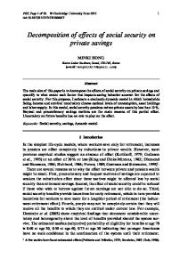
FIG. 5. Cross-section SEM images of the phototarget 70 nm line features after various plasma treatments.
2648
Kim et al.: Effects of various plasma pretreatments on 193 nm photoresist
2648
TABLE I. FTIR analysis on the chemical content changes of the 193 nm photoresist caused by various plasma treatments. All of the values are normalized to the as-coated 共no plasma treatment兲 193 nm photoresist, in percent unit, and represent how much both CO and CHx contents are decreased as a result of each plasma treatment.
关CO兴 共%兲 关CHx兴 共%兲
No plasma treatment
HBr
Ar
H2
Cl2
100 100
22 77
57 79
38 71
25 67
of 60 ° C/process time of 27 s. The end point of BARC etching was about 20 s, although it varied somewhat according to the previous plasma treatments. For the SiO2 hard-mask etching, the following process conditions were chosen which moderately deformed the 193 nm photoresist and with which the end points of the SiO2 hard-mask etching were about 25 s: 5 mT/ 600 W TCP power/100 W bias power/50 SCCM CF4 / 50 SCCM CH2F2/ESC 60 ° C / 40 s. III. RESULTS AND DISCUSSIONS There are three distinct groups of FTIR peaks to be mentioned. Between 800 and 1500 nm wavelengths, that is, within the 共fingerprint兲 region of interest, in Fig. 2, the photoresist as coated shows the most complex bundle of peaks. The FTIR spectra of the HBr, H2, and Cl2 plasma treated photoresist films show fewer distinct peaks. It is likely that the HBr, H2, and Cl2 plasmas give substantial chemical influences on the 193 nm photoresist. Figure 3 shows the two characteristic peaks between 1650 and 1850 nm, which are thought to represent the CO groups of the ester and the maleic anhydride in the 193 nm photoresist.9,15 The 1790 nm peak is notably decreased for all of the plasma pretreatments. The HBr, H2, and Cl2 plasma treatments more effectively reduce the CO peaks than the Ar plasma treatment. It is likely that there are vigorous substitution reactions of the H, Cl, and Br radicals with the CO groups in the 193 nm photoresist, which release the CO. Very little variation of the peaks due to plasma treatments is observed in the hydrocarbon 共CHx兲 region of the spectra between 2800 and 3100 nm, as seen in Fig. 4. For all of the plasma treatments, it is clear that the CO groups are substituted, vaporized, or modified more spontaneously than the CHx groups. The CO groups are not stable against plasma etching and loss of or chemical substitution of them can cause surface roughness.7–9 Quantification of the FTIR results for the CO and CHx contents is summarized in Table I. For each plasma pretreatment, we TABLE II. Remaining thickness of the photoresist films after plasma treatments. All thickness values were measured from cross-section SEM images.
Remaining thickness 共nm兲
Sample
No plasma treatment
HBr
Ar
H2
Cl2
Nonpatterned
108
99
89
68
95
Patterned
110
106
109
83
117
J. Vac. Sci. Technol. B, Vol. 24, No. 6, Nov/Dec 2006
FIG. 6. Top-down SEM images of the phototarget 70 nm line features after various plasma treatments.
integrated the two wavelength ranges, 1690–1810 and 2840– 3051 nm, respectively. As shown in Table II and Fig. 5, the H2 plasma treatment reduces the photoresist thickness substantially. To correct for the resist thickness changes occurring during the plasma pretreatments on the intensities of the CO and CHx groups, we divided each integrated value by the corresponding remaining resist thickness measured from the cross-section SEM images of the patterned samples in Table II. To simplify the discussion, we normalized each value to that of the photoresist as coated, in the percent unit. These manipulated values are listed in Table I. Table I indicates that the halogen Br and Cl radicals are more effective for removing the CO groups from 193 nm photoresist than the H radical. All of the plasma treatments show similar and relatively minor impact on the CHx groups. As shown in Fig. 6 and Table III, only the Cl2 plasma pretreatment deteriorates the LWR significantly from 4.7 nm as photoprocessed to 7.7 nm and reduces the linewidth severely. The other 共HBr, Ar, and H2兲 plasma pretreatments do not impose notable impacts on the linewidth and roughness values while the H2 plasma records the lowest LWR value. It is likely that the Cl radicals have the highest etching rate of the 193 nm photoresist in the horizontal direction and their reaction rates with each constituent of the 193 nm photoresist are quite different from one another, which results in the worst LWR value for the Cl2 plasma treatment. From Fig. 5, it must be pointed out that the Cl2 plasma treatment generates significant and irregular morphology on the top surface of the photoresist as well as considerable horizontal defor-
TABLE III. LWR and linewidth data after plasma treatments at the 70 nm patterned lines in Fig. 6.
LWR 共nm兲 Linewidth 共nm兲
As photoprocessed
HBr
Ar
H2
Cl2
4.7 71
5.2 60
5.3 61
3.5 67
7.7 47
2649
Kim et al.: Effects of various plasma pretreatments on 193 nm photoresist
2649
FIG. 7. Top-down SEM images of the phototarget 70 nm line features after the BARC and hard-mask etching processes following the plasma pretreatments.
FIG. 8. Top-down SEM images of the phototarget 80 nm line features after the BARC and hard-mask etching processes following the plasma pretreatments.
mation, which implies that Cl elements are very unstable in the 193 nm photoresist and vigorously react with the components of the 193 nm photoresist. Table II shows that the trend of the remaining photoresist thickness is about the same for both nonpatterned and patterned samples, though there is an offset between them. Only the H2 plasma pretreatment reduces the photoresist thickness notably. It is likely that the H radicals have the highest etching rate in the vertical direction while the reaction rates with each constituent of the 193 nm photoresist are almost uniform to result in the best LWR value for the H2 plasma treatment. The top-down SEM images obtained just after the BARC and hard-mask etching processes following the various plasma pretreatments are shown in Figs. 7 and 8. Of course, the smaller 70 nm target linewidth lines 共Fig. 7兲 show greater deformation than the larger 80 nm linewidth lines 共Fig. 8兲. When we look at the 70 nm patterned lines in Fig. 7 closely, we notice two distinctive types of roughness. The no plasma and the Ar plasma pretreated samples exhibit low-frequency roughness which repeats about every 400 nm and which is seen as a partial collapse of the photoresist line as depicted in Fig. 7. This low-frequency roughness deteriorates the LWR severely as shown in Table IV. The samples pretreated by both the H2 and HBr plasmas, after the BARC and hardmask etching processes, show another type of deformation at the 70 nm patterned lines in Fig. 7, a high-frequency rough-
ness, occurring about every 100 nm. However, the impact of the high-frequency roughness on the LWR values is much smaller than that of the low-frequency roughness as seen in Table IV. It is clear that the Cl2 plasma pretreatment generates the most severe side reactions with the 193 nm photoresist during the following BARC and hard-mask etching processes, which produces missing portions of pattern at its worst at the phototarget of 70 nm. The Cl2 plasma treated photoresist films 共Table III兲 showed the smallest linewidth of the four plasmas tested. This accounts for the primary reason for the Cl2 pretreatment exhibiting the most severe pattern deformation of the various plasma treated samples shown in Figs. 7 and 8. The SEM images of Figs. 7 and 8 and the LWR values of Table IV support this finding. From the CO content data in Table I, the SEM images in Fig. 7, and the LWR values in Table IV, we reconfirm that the photoresist pretreated by the HBr plasma is most resilient against the following BARC and hard-mask etching processes, which was already reported in other papers and correlated with its very low CO content after the HBr plasma pretreatment.14,15 The photoresist pretreated by the H2 plasma, which keeps relatively low CO content as in Table I, shows moderate deformation after the following etching processes. The HBr and H2 plasmas sufficiently reduce the CO content of 193 nm photoresist and effectively prevent the low-frequency roughness, which is most deteriorative, dur-
TABLE IV. LWR and linewidth data just after the BARC and hard-mask etching processes following the plasma pretreatments. Photo target linewidth 共nm兲
No plasma treatment
HBr
Ar
H2
Cl2
70
LWR 共nm兲 Linewidth 共nm兲
16 64
7.4 58
20 74
9.1 53
43 24
80
LWR 共nm兲 Linewidth 共nm兲
7.6 65
5.3 66
9.4 67
7.0 63
10 57
JVST B - Microelectronics and Nanometer Structures
2650
Kim et al.: Effects of various plasma pretreatments on 193 nm photoresist
FIG. 9. Top-down SEM images of the phototarget 70 nm line features after ashing process.
ing the following BARC and hard-mask etching processes. Of course, the no plasma and the Ar plasma pretreated photoresists, which contain substantial CO group content as in Table I, show severe deformation, the low-frequency roughness, after the following BARC and hard-mask etching processes as shown in Fig. 7. Therefore, we correlate the lowfrequency roughness with the CO content of 193 nm photoresist, which can be reduced substantially through the HBr or H2 plasma pretreatments. However, the photoresist pretreated by the Cl2 plasma, which contains CO groups as little as the photoresist pretreated by the HBr or H2 plasma, is completely collapsed during the following etching processes as shown in Fig. 7. Because the chemically inert Ar plasma is much less effective in reducing CO content than the other HBr, H2, and Cl2 plasmas as shown in Table I, it is likely that H, Br, and Cl radicals are incorporated into the 193 nm photoresist through spontaneous substitution reactions with the CO groups in the 193 nm photoresist and subsequent rearrangement reactions. The Cl elements incorporated into the 193 nm photoresist during the Cl2 plasma pretreatment are very unstable and cause vigorous reactions, which result in the most severe deformation, whereas the H and Br elements are relatively stable in the 193 nm photoresist to produce the least deformation as seen in Fig. 7. For the phototarget of 80 nm, only the Cl2 plasma pretreated
2650
sample shows severe deformation after the subsequent BARC and hard-mask etching processes as shown in Fig. 8. We mention that the linewidth of the photoresist determines the extent of the low-frequency roughness caused by the loss of CO groups during the BARC and hard-mask etching processes because we do not find significant photoresist collapse for both the no plasma and the Ar plasma pretreated samples at the phototarget of 80 nm in Fig. 8. However, even for the wider 80 nm features, both the no plasma and the Ar plasma pretreated samples result in a little higher LWR values as shown in Table IV, though there is no explicit photoresist collapse in Fig. 8. After the ashing process, at first glance, we find an opposite trend in view of the LWR. For the phototarget 70 nm features after the ashing process in Fig. 9, the Ar pretreated sample shows the smoothest line features, which contradict the findings obtained just after the BARC and hard-mask etching processes in Fig. 7. However, for the no plasma and the Ar plasma treated samples, there is still severe long-range deformation, the so-called low-frequency roughness, as well as the irregular hard-mask slope which is seen as white scum along the lines. The long-range deformation and irregular hard-mask slope are depicted in Fig. 9. They are likely caused by the photoresist collapse during the BARC and hard-mask etching processes through the loss of CO groups. The LER and LWR values for the phototarget 70 nm features after ashing process in Table V, which were obtained with the baseline near the bottom of the features as seen in Fig. 1, correctly describe both the low-frequency roughness 共longrange deformation兲 and the irregular hard-mask slope quantitatively. However, we notice that the samples pretreated by both the HBr and H2 plasmas show the characteristic highfrequency roughness 共short-range deformation兲 after the ashing process as depicted in Fig. 9, which can also be noticed just after the BARC and hard-mask etching processes as seen in Fig. 7. It is likely that even the H and Br elements as well as the Cl elements incorporated into 193 nm photoresist no longer remain stable enough during the subsequent BARC and hard-mask etching processes and lead to the highfrequency roughness as seen in Figs. 7 and 9. However, this high-frequency roughness is much less deteriorative than the low-frequency roughness in view of both the LWR and LER as shown in Table V, even for the 70 nm patterns. We find the same trend in the phototarget of 80 nm in Table V, al-
TABLE V. LWR and linewidth data after ashing process. Photo target linewidth 共nm兲
No plasma treatment
HBr
Ar
H2
Cl2
70
LER 共nm兲 LWR 共nm兲 Linewidth 共nm兲
12 11 59
6.1 6.1 57
8.5 11 63
5.4 6.2 54
¯ ¯ ¯
80
LER 共nm兲 LWR 共nm兲 Linewidth 共nm兲
5.2 7.6 70
3.5 5.1 67
5.8 7.4 76
3.0 4.1 65
13 8.6 57
J. Vac. Sci. Technol. B, Vol. 24, No. 6, Nov/Dec 2006
2651
Kim et al.: Effects of various plasma pretreatments on 193 nm photoresist
FIG. 10. Top-down SEM images of the phototarget 80 nm line features after ashing process.
though it is difficult to order the various plasma pretreatments in terms of line roughness visually from the SEM images in Fig. 10. Of the plasmas evaluated in this work as a pretreatment method for 193 nm photoresist, the HBr or H2 plasmas, which reduce the CO content of 193 nm photoresist substantially, are the most effective on minimizing the LWR and LER increases caused by the subsequent BARC and hardmask etching processes, although the application of the H2 plasma pretreatment is limited by its severe vertical photoresist loss. However, even the HBr and H2 plasma pretreatments generate the high-frequency roughness though it is moderate. Therefore, we conclude that an inert gas plasma, which will not generate any side reactions during the subsequent etching processes, should be the best as a plasma pretreatment for 193 nm photoresist, if it is optimized to reduce the CO content of the 193 nm photoresist less than 40% of the original CO content as coated.
2651
ited by its severe vertical photoresist loss. We correlate the structural loss of 193 nm photoresist during etching processes with the removal of the CO groups of 193 nm photoresist. From the FTIR analysis, we find that the HBr and the H2 plasma pretreatments reduce the CO content substantially to about 20%–40% of that of the 193 nm photoresist as coated. The Ar plasma pretreated photoresist retains about 60% of the CO content of the pristine 193 nm photoresist. The elements incorporating into the 193 nm photoresist during plasma pretreatment also contribute to line roughness increase during the subsequent BARC and hard-mask etching processes. The Cl2 plasma pretreatment, which has a similar impact on CO removal from 193 nm photoresist as the HBr and the H2 plasma pretreatments, deteriorates the LWR from just after the pretreatment and results in the most severe line deformation after the subsequent BARC and hard-mask etching processes. It is likely that the Cl elements do not remain stable in the 193 nm photoresist during the subsequent plasma etching processes and generate severe side reactions. The H and Br elements also interact with the 193 nm photoresist and generate the high-frequency roughness, which is not observed significantly in the case of the no plasma and the Ar plasma pretreatments, although the effects of the high-frequency roughness on the LWR value are much smaller than those of the low-frequency roughness. Of the plasmas evaluated in this work as a pretreatment method, the HBr or H2 plasmas, which reduce the CO content of the 193 nm photoresist substantially, are the most effective on suppressing the LWR and LER increases caused by the BARC and hard-mask etching processes. However, even the HBr and H2 plasma pretreatments generate the moderate high-frequency roughness. Therefore, we conclude that an inert gas plasma, which will not generate any side reactions during the subsequent etching processes, should be the best choice as a plasma pretreatment for 193 nm photoresist, if it is optimized to reduce the CO content of the 193 nm photoresist less than 40% of the original CO content as coated.
IV. CONCLUSIONS H. Ito, IBM J. Res. Dev. 45, 683 共2001兲. D. Attwood, J. Phys. D 37 共2004兲. 3 G. M. Wallraff et al., J. Vac. Sci. Technol. B 11, 2783 共1993兲. 4 H. Gokan, S. Esho, and Y. Ohnishi, J. Electrochem. Soc. 130, 143 共1983兲. 5 T. Sarubbi, M. Ross, M. Neisser, T. Kocab, B. Beauchemin, W. Livesay, S. Wong, and W. Ng, Proc. SPIE 4345, 21 共2001兲. 6 M. S. Kim, J. W. Park, H. J. Kim, B. J. Jun, M. G. Gil, B. H. Kim, M. Ross, and W. Livesay, Proc. SPIE 4345, 737 共2001兲. 7 J. Kim, Y. S. Chae, W. S. Lee, W. Shon, C. J. Kang, W. S. Han, and J. T. Moon, J. Vac. Sci. Technol. B 21, 790 共2003兲. 8 L. Ling, X. Hua, X. Li, G. S. Oehrlein, E. A. Hudson, P. Lazzeri, and M. Anderle, J. Vac. Sci. Technol. B 22, 2594 共2004兲. 9 N. Negishi, H. Takesue, M. Sumiya, T. Yoshida, Y. Momonoi, and M. Izawa, J. Vac. Sci. Technol. B 23, 217 共2005兲. 10 B. J. Lin, J. Microlithogr., Microfabr., Microsyst. 533, 3 共2004兲. 11 P. Oldiges, Q. Lin, K. Petrillo, M. Sanchez, M. Ieong, and M. Hargrove, Proceedings of the International Conference on Simulation of Semiconductor Processes and Devices, Seattle, WA, 6–8 September 2000 共IEEE, New York, 2000兲, p.131. 12 C. H. Diaz, H.-J. Tao, Y.-C. Ku, A. Yen, and K. Young, IEEE Electron Device Lett. 22, 287 共2001兲. 13 H.-W. Kim, J.-Y. Lee, J. Shin, S.-G. Woo, H.-K. Cho, and J.-T. Moon, 1
As a pretreatment method of 193 nm photoresist to reduce the 193 nm photoresist roughness induced by plasma etching processes, the four plasma treatments 共HBr, Ar, H2, and Cl2 gases兲 were evaluated using 70 and 80 nm line features. We find two distinctive types of roughness of the 193 nm photoresist pretreated by the various plasmas after the subsequent BARC and hard-mask etching processes. The low-frequency roughness repeats in about every 400 nm while the highfrequency roughness repeats in about every 100 nm. It is likely that the low-frequency roughness is caused by collapse of the 193 nm photoresist and deteriorates the LWR value significantly. The no plasma and the Ar plasma pretreated samples show the low-frequency roughness with notable increase in the LWR values. The HBr and the H2 plasma pretreatments, which mainly lead to the high-frequency roughness, are the most effective on maintaining the LWR value against the BARC and hard-mask etching processes, although the application of the H2 plasma pretreatment is limJVST B - Microelectronics and Nanometer Structures
2
2652
Kim et al.: Effects of various plasma pretreatments on 193 nm photoresist
IEEE Trans. Electron Devices 51, 1984 共2004兲. H. Struyf, Q. T. Le, T. Dupont, W. Boullart, and S. Vanhaelemeersch, 26th International Symposium on Dry Process, Tokyo, Japan, 30 November–1 December 2004 共unpublished兲, p. 1-05.
14
J. Vac. Sci. Technol. B, Vol. 24, No. 6, Nov/Dec 2006
15
2652
A. P. Mahorowala, K.-J. Chen, R. Sooriyakumaran, A. Clancy, D. Murthy, and S. Rasgon, Proc. SPIE 5753, 380 共2005兲. 16 The International Technology Roadmap for Semiconductor 共Semiconductor Industry Association, San Jose, CA, 2003兲.