Influence of oxide hard mask on profiles of sub-100 nm Si and SiGe gates Denis Shamiryan, Vasile Paraschiv, Sabrina Locorotondo, Stephan Beckx, Werner Boullart, and Serge Vanhaelemeersch IMEC, Kapeldreef 75, Leuven 3001, Belgium
共Received 23 March 2005; accepted 11 July 2005; published 23 September 2005兲 Oxide hard mask was found to have a profound effect on sub-100 nm Si and SiGe gates profiles. The gates patterned with hard mask only 共photoresist is stripped after hard mask patterning兲 exhibit considerable profile distortion. It has been found that the distortion is caused by the ions deflection due to the charge accumulation on the hard mask. The distortion can be avoided by using either a thinner 共15 nm–20 nm兲 hard mask 共that accumulates less charges兲 or by increasing the ion energy, using higher 共above 150 W兲 bias power 共ions impinging the surface with higher speed are less likely to be deflected兲. © 2005 American Vacuum Society. 关DOI: 10.1116/1.2019386兴
I. INTRODUCTION Continuous scaling of semiconductor devices in combination with the introduction of new materials 共such as metals or germanium兲 into the gate stack had a significant impact on the pattering process. Not only development of appropriate recipes, for a significant number of metals, but also revising the existing ones for standard materials like polysilicon became of high importance. One specific issue is linked towards introduction of the hard mask 共HM兲 for polysilicon patterning. There are at least three reasons that supports this approach: photoresist 共PR兲 follows the scaling trend and reaches its limits regarding the full stack patterning, most of the new materials are incompatible with the standard PR wet strip chemistries and possibility to avoid exposure of the gate dielectric to oxygen plasma. Smaller features require thinner photoresist in order to be printed correctly. A straightforward example is 193 nm lithography that is using photoresist materials thinner than the one used for 248 nm and consists of “weaker” polymer backbones. At some point resist becomes too thin for successfully masking the gate during the dry etch. Introduction of HM becomes necessary. The second reason for the HM introduction is incompatibility of new materials with wet strip/polymer removal chemistries. For example, Ti-based materials 共like TiN or TiNC兲 that are used as metal gates are etched by ammonia-peroxide mixture 共APM兲 or sulfuric acid-peroxide mixture 共SPM兲 共Ref. 1兲 that are conventionally used for strip and/or polymer removal after gate etch. Germanium that is used in SiGe sacrificial gates is also compatible neither with APM nor with SPM. An alternative solution is a HM-based etch when PR is stripped in situ during gate etch immediately after HM opening. In situ strip before gate patterning reduces polymer formation by removing the source of hydrocarbon. Finally, traditionally an oxygen plasma dry strip process applied after advanced metal gate/high-k etch is undesirable since oxygen plasma might oxidize Si/high-k interface increasing the electrical oxide thickness 共EOT兲.2 In situ strip after HM opening, before reaching the substrate, avoids this problem. It is known that presence of an insulating layer may have an impact on the etch profiles due to localized charge accumulation. There are three main types of profile distortions, 2194
J. Vac. Sci. Technol. B 23„5…, Sep/Oct 2005
addressed in many papers both experimentally and theoretically: microtrenching at the bottom of the trenches etched in Si 共Refs. 3 and 4兲 or silicon oxide,5 “notch” formation—an undercut at the bottom of a silicon gate near the interface with the gate dielectric,6,7 and bowing of the side walls 共or undercut under the etch mask兲 of the etched features.3,8 Two mechanisms are believed to be responsible for profile distortions: localized surface charging that influences ion trajectories and ion scattering from the side walls of the etched features. The localized charging effect has been proposed to occur as a result of the difference in angular distribution between ions and electrons.5 The ion angular distribution is highly anisotropic, whereas the electron angular distribution is nearly isotropic. As a result, the sidewalls of the oxide HM can be easily negatively charged by electrons that can deflect ion trajectories. The ion scattering occurs when the ions hit a sloped sidewall of an etched feature and results mainly in microtrenching at the bottom of the feature.9 It should be noted that the microtrenching can be caused both by hard mask charging and by the ion scattering. The influence of the charging was proven by Schaepkens and Oehrlein10 by means of magnetic field that caused different charging of the left and right side of the hard mask resulting in asymmetric micrtotrenching. The influence of the ion scattering was proven in a work by Bogart et al.11 where no difference in microtrenching was observed both for insulating 共SiO2兲 and conductive 共W兲 hard masks. In this article we will focus on one type of the profile distortion only—undercut under the oxide HM that is usually attributed to the ion deflection caused by the HM charging and not by the ion scattering. The gate dimensions are under 100 nm. Besides the “traditional” polysilicon gates we are discussing also the SiGe patterning process. The side wall trenching is mostly relevant for etching trenches in Si substrate, while the “notch” attributed to the charging of the gate dielectric is not an issue if the etch stops on a conductive layer.12 Although this effect is already described in the aforementioned papers, typically features of 200 nm–300 nm width are studies with the HM thickness of about 500 nm. Profile distortions that are negligible or acceptable for such dimen-
0734-211X/2005/23„5…/2194/4/$22.00
©2005 American Vacuum Society
2194
2195
Shamiryan et al.: Influence of oxide hard mask on profiles of sub-100 nm Si and SiGe
2195
TABLE I. Parameters of the Si gate etch recipe. Parameter
Value
Pressure TCP power Bias power Cl2 flow HBr flow CF4 flow O2 flow
5 mT 250 W varied 60 sccm 90 sccm 15 sccm 5 sccm
sions might be significant for the sub-100 nm gates studied in this paper. Xu et al.13 reported patterning of 20 nm poly-Si gate patterning where profile distortions were reported, but they were not related to the HM charging. In our experiments thinner films 共60 nm oxide HM, 100 nm poly-Si兲 are used due to smaller lateral dimensions. As thinner films require higher selectivities and lower etch rate for better profile control, lower power settings must be used. In the papers reviewed above, one of the crucial parameters for the profile distortion, bias power, is usually varied in the range of 150– 350 W that might be too high for the thin films used in the advanced gate stacks. Also, it is not always clear from the papers whether the resist used for the HM patterning is stripped before the etch was continued. The presence of the resist could make a difference for the profile control, as the resist can be a source of polymers that could be redeposited on the side walls of the gate making a passivating layer. To our knowledge this effect is not reported for SiGe gates, yet. The poly-Si/ TiN/ TaN stack consists of 100 nm poly-Si, 10 nm TiN, and 15 nm TaN. The poly-Si provides bulk gate that is compatible with a standard gate manufacturing. TaN acts as a metal gate with an appropriate work function. A TiN layer between TaN and poly-Si is used to prevent TaN oxidation that may result in parasitic capacitance between poly and TaN. The gate dielectric may be either high-k 共HfO2 or Hf silicate兲 or conventional SiON. Hard mask is removed after the gate patterning in HF based solutions, therefore, the hard mask consumption is not of a concern. The poly-SiGe/ poly-Si gate stack consists of 80 nm SiGe and 20 nm of Si below the SiGe. The SiGe layer serves as a sacrificial gate that is removed at the later stages of the device fabrication selectively towards the underlying Si. The remaining Si is then fully silicided forming a metal gate. In this approach the hard mask should protect the gate at the later stages of processing 共prior to the removal of the sacrificial gate兲, therefore, hard mask damage by the plasma etch should be minimized. We are presenting only on the etching of the top part of the gate stack: poly-Si in the case of poly-Si/ TiN/ TaN gate and poly-SiGe in the case of SiGe/ Si gate. Even more specific, the scope of the paper is only the first etch step—main etch that defines the gate profile. JVST B - Microelectronics and Nanometer Structures
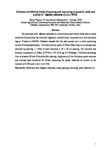
FIG. 1. Poly-Si gate profile etched with HM. The bias power is 90 W. TiN and TaN are not etched.
II. EXPERIMENT In both cases 共Si/ TiN/ TaN and SiGe/ Si兲 a 60 nm oxide 关plasma-enhanced chemical vapor deposition 共PECVD兲兴 HM was used in combination with an organic bottom antireflective coating 共BARC兲 layer of 80 nm. 193 nm lithography was used for pattern transfer. 共PR thickness= 200 nm兲. All dry etch processes were carried out in a Lam research Versys 2300 etch chamber on 200 mm wafers. This particular etch reactor uses transformer coupled plasma 共TCP兲 that allows plasma power and substrate bias 共or bottom electrode power兲 to be controlled separately. Oxide HM was patterned using CF4 / CH2F2 plasma with 25% CH2F2. Such chemistry etches oxide with reasonable selectivity towards Si and SiGe. After that, the remaining resist and polymers formed from hydrogen-containing fluorocarbon gases have been removed by an in situ strip using oxygen plasma. Poly-Si gates were etched using Cl2 / HBr/ CF4 / O2 gases 共the recipe details are given in Table I兲. For SiGe gates we used only pure HBr 共Cl2 and CF4 were excluded since they produce too much damage to Ge兲. The etch process has been stopped after the main
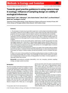
FIG. 2. Poly-SiGe gate profile etched with HM. The bias power is 90 W. The underlying Si is not etched. Poor contrast in SEM between SiGe and Si does not allow these two layers to be distinguished.
2196
Shamiryan et al.: Influence of oxide hard mask on profiles of sub-100 nm Si and SiGe
2196
FIG. 5. Poly-Si gate profile etched with HM. The bias power is 30 W.
FIG. 3. Scheme of ion deflection by negatively charged hard mask.
etch. All the wafers were cross-sectioned and inspected by scanning electron microscopy 共SEM兲. III. RESULTS AND DISCUSSION First tests for patterning poly-Si gates with an oxide HM instead of PR used the recipe developed for standard polySi/PR stack. Contrary to previous results with no HM, this time the profile is bowed with sidewalls laterally attacked as shown in Figs. 1 and 2. A possible explanation for the HM impact on poly-Si etch profile is the HM charging effect described already in literature. During the etch, the hard mask collects negative charges and becoming negatively charged. Positively charged ions accelerated towards the substrate by negative substrate bias are deflected from the perpendicular trajectories when passing near the charged HM as schematically
FIG. 4. Poly-Si gate profile etched with HM. The HM was thinned down to approximately 15 nm. The bias power is 90 W. J. Vac. Sci. Technol. B, Vol. 23, No. 5, Sep/Oct 2005
shown in Fig. 3. This effect expected to be more pronounced at low pressures8 共5 mT in our case兲 as ions experience less scattering collisions and their trajectories are more influenced by the local electric fields. If the ion deflection theory is correct than the profile should depend on two parameters: HM thickness and ion energy. As Giapis et al.14 have shown by simulation, a thinner HM should contain less charge and produce less deflection. In order to thin the HM a special HM thinning step has been applied after PR in situ strip. The same chemistry and plasma settings were used for the thinning step as for the HM patterning step itself. The result of the HM thinning implementation in poly-Si gate etch is shown in Fig. 4. The gate profile became straighter as was expected. As was explained before, in the case of SiGe the HM should be kept after the etch since it is necessary for the further processing. Therefore, for the SiGe gates the HM thinning is not an option. The ion energy was varied by changing the bias power. The bias power of 90 W was used in the initial recipe. Two other extreme values, 30 W and 150 W, have been tested 共for poly-Si gates兲, the results are shown in Figs. 5 and 6, respectively. No HM thinning was used while all the other etch
FIG. 6. Poly-Si gate profile etched with HM. The bias power is 150 W.
2197
Shamiryan et al.: Influence of oxide hard mask on profiles of sub-100 nm Si and SiGe
FIG. 7. Poly-SiGe gate profile etched with HM. The bias power is 50 W.
parameters were kept the same. The gate etched with bias power of 30 W shows the profile distortion that is much more pronounced than for 90 W 共cf. Fig. 1兲. The gate etched with bottom power of 150 W shows no profile distortion. One can see that bias power has profound influence on the gate profile—higher ion energy allows the distortion to be avoided while the low ion energy greatly enhances the distortion that fits to the HM charging/ion deflection theory. Similar results were obtained for poly-SiGe gates 共see Figs. 7 and 8兲, where the bias power was also found to be one of the main factors that influence the gate profile. It should be noted that the distortion in the case of SiGe is less pronounced as compared to the poly-Si case. This can be explained by the difference in the chemistry used. While Si is etched by rather reactive Cl2 / HBr/ CF4 / O2 gas mixture, the SiGe gates are etched by pure HBr that is less aggressive towards SiGe. Moreover, Br is the heaviest element among the used ones and it is less likely to be deflected. The fact that the profile distortion is not observed when the etch is performed with a resist mask only have two possible explanations: the resist mask might be less charged than the oxide one that would produce less ion deflection; another possible cause is the release of hydrocarbons from the resist mask during the etching that can form a protective layer on the sidewalls. It should be noted that increasing ion energy makes the etch process less selective towards the HM. One can see from Figs. 5 and 6 that the consumption of the HM increases with increase of the bias power. Moreover, the top of the HM becomes rounded with increased bias power that can be attributed to the sputtering of the top corners by more energetic ions. As HM should be removed immediately after the gate patterning, its shape is not a concern. However, it may become one if a scheme where the HM should be kept intact would be used.
JVST B - Microelectronics and Nanometer Structures
2197
FIG. 8. Poly-SiGe gate profile etched with HM. The bias power is 220 W.
IV. CONCLUSIONS Hard mask was found to have a strong influence on the profile of sub-100 nm gates 共Si or SiGe兲. Strong undercut under the HM is observed at low pressure 共5 mT兲 when bias power is below 150 W. The influence is explained by a wellknown theory of HM charging. The negative charge in the HM deflects positively charged ions producing bowing or undercut of the gate. Thicker HM and lower ion energy produces stronger profile distortion, while thinner HM 共15 nm–20 nm兲 and higher ion energy result in straighter gate profile. 1
H. Akatsu, D. E. Kotecki, J. J. Lian, and H. Shen, U.S. Patent No. 6 379 5777 共2002兲. 2 S. A. Vitale and B. A. Smith, J. Vac. Sci. Technol. B 21, 2205 共2003兲. 3 M. A. Vyvoda, M. Li, and D. B. Graves, J. Vac. Sci. Technol. A 17, 3293 共1999兲. 4 Wedong Jin and Herbert H. Sawin, J. Vac. Sci. Technol. A 21, 911 共2003兲. 5 J. C. Arnold and H. H. Sawin, J. Appl. Phys. 70, 5314 共1991兲. 6 Gyeong S. Hwang and Kostantinos P. Giapis, J. Appl. Phys. 81, 3433 共1997兲. 7 Jane P. Chang and Herbert H. Sawin, J. Vac. Sci. Technol. B 19, 1870 共2001兲. 8 J. M. Lane, F. P. Klemens, K. H. A. Bogart, M. V. Malyshev, and J. T. C. Lee, J. Vac. Sci. Technol. A 18, 188 共2000兲. 9 A. C. Westerheim, A. H. Labun, J. H. Dubash, J. C. Arnold, H. H. Sawin, and V. Yu. Wang, J. Vac. Sci. Technol. A 13, 853 共1995兲. 10 Marc Schaepkens and Gottlieb S. Oehrlein, Appl. Phys. Lett. 72, 1293 共1998兲. 11 K. H. A. Bogart, F. P. Klemens, M. V. Malyshev, J. I. Colonell, V. M. Donnelly, J T. C. Lee, and J. M. Lane, J. Vac. Sci. Technol. A 18, 197 共2000兲. 12 Che-Heung Kim and Yong-Kweon Kim, J. Micromech. Microeng. 15, 358 共2005兲. 13 Qiuxia Xu, Qian He, Mong Liu, Yuying Zhao, Baoqing Chen, Zhengsheng Han, Tianchun Ye, and Dexin Wu, J. Vac. Sci. Technol. B 21, 2352 共2003兲. 14 K. P. Giapis, G. S. Hwang, and O. Joubert, Microelectron. Eng. 61-62, 835 共2002兲.