This article was originally published in a journal published by Elsevier, and the attached copy is provided by Elsevier for the author’s benefit and for the benefit of the author’s institution, for non-commercial research and educational use including without limitation use in instruction at your institution, sending it to specific colleagues that you know, and providing a copy to your institution’s administrator. All other uses, reproduction and distribution, including without limitation commercial reprints, selling or licensing copies or access, or posting on open internet sites, your personal or institution’s website or repository, are prohibited. For exceptions, permission may be sought for such use through Elsevier’s permissions site at: http://www.elsevier.com/locate/permissionusematerial
Microelectronic Engineering 84 (2007) 609–618 www.elsevier.com/locate/mee
py
Spacer defined FinFET: Active area patterning of sub-20 nm fins with high density
co
B. Degroote, R. Rooyackers *, T. Vandeweyer, N. Collaert, W. Boullart, E. Kunnen, D. Shamiryan, J. Wouters, J. Van Puymbroeck, A. Dixit, M. Jurczak IMEC vzw, SPDT, Kapeldreef 75, B-3001 Leuven, Belgium
al
Received 12 May 2006; received in revised form 24 November 2006; accepted 15 December 2006 Available online 22 December 2006
on
Abstract
pe
rs
We present a method to obtain Si-fins with a critical dimension (CD) below 20 nm, separated by a minimum distance of 25 nm and connected by a common source/drain (S/D) pad. The method comprises of recursive spacer defined patterning to quadruple the line density of a 350 nm pitch resist pattern defined by 193 nm lithography. Spacer defined patterning is combined with resist based patterning to simultaneously define fins and S/D pads in a Silicon on Insulator (SOI) film. CD and Line Width Roughness (LWR) analysis was done on top down SEM images taken in a center die and in an edge die of a 200 mm wafer. The average CD is 17 nm in the center of the wafer and 18 nm at the edge. The LWR is 3 nm for both center and edge. Additional process steps to remove etch damage and round the top corner of the fin (i.e. oxidation followed by H2 anneal) further reduce the CD to 13 nm. Ó 2007 Elsevier B.V. All rights reserved. Keywords: Fin; MuGFET; Spacer defined patterning; Critical dimension (CD); Line width roughness (LWR); Sub-20 nm pattern
1. Introduction
Au
th o
r's
FinFET devices currently receive a lot of attention because of their potential use in advanced nodes like the 32 nm-node and below. An important advantage over the planar architecture is the better control on Short Channel Effects (SCE) [1,2]. In addition, the FinFET architecture looks more promising for scaling [3]. The effective device width can be increased by increasing either the fin height or the fin density. The former option makes process integration more critical because of the increased topography. The latter is more demanding from lithographic point of view. Spacer patterning technology is very attractive in order to overcome the limits of conventional lithography techniques in terms of pattern density [4]. It enables to improve pattern fidelity and CD uniformity.
*
Corresponding author. E-mail address:
[email protected] (R. Rooyackers).
0167-9317/$ - see front matter Ó 2007 Elsevier B.V. All rights reserved. doi:10.1016/j.mee.2006.12.003
To our knowledge no reports have been made on spacer defined fins with a small CD (i.e. <20 nm) being successfully integrated in a MuGFET transistor. Choi et al. have demonstrated spacer defined Si-structures with sub-10 nm fins connected by source/drain pads [5]. However, for these structures no sacrificial oxidation step was done. This means that the etch damage is not removed. The authors of Ref. [5] further report on other fin structures where a thermal oxidation of 10 nm was done to remove the etch damage. However, these fins do not have a sub-20 nm CD (i.e. 20–25 nm) and additionally they do not have a straight profile. A relatively large oxide layer of 10 nm needs to be removed after oxidation, which results in a considerable recess of the Buried Oxide (BOX) and a large undercut of the fin and the S/D pad. No electrical results are reported for these fins. The same authors report only in Ref. [6] on the demonstration of a functional doublegate FinFET device with a 40 nm spacer defined Si-fin structure connected by S/D pads. In this paper we present a method to obtain sub-20 nm fins, with a straight profile, separated by a minimum dis-
B. Degroote et al. / Microelectronic Engineering 84 (2007) 609–618
tance of 35 nm, and connected by a common S/D pad. This was achieved by two repetitions of spacer definition starting from a pattern with a pitch of 350 nm. The principle of recursively applying spacer defined patterning was demonstrated in Ref. [7]. Si-structures with a line width of 70 nm spaced by 80 nm were obtained from a conventional lithography pattern with a pitch of 600 nm after three repetitions of spacer definition. We have used the same principle but with a different integration scheme, obtaining a considerably smaller fin CD with a considerably smaller separation. In addition, the fin structures presented in this paper can be successfully integrated for logic applications by using an extra mask to clear out part of the spacer hard mask in areas were only one fin is needed. Thus an extra mask is required if single fins with the same dimension are needed. Wider fin regions can be defined together with the common S/D pads, thus by conventional lithography.
3. Results and discussion In Section 3.1 we explain what process steps are needed to obtain high density fin patterning by recursive spacer defined patterning combined with the definition of S/D pads. In Section 3.2 we focus on the CD performance and the line width roughness analysis. In Section 3.3 some process issues are discussed. 3.1. Process flow
al
co
Before looking at some of the process steps individually we give an overview of the overall process flow, schematically shown in Fig. 1. First we pattern a sacrificial SiGe hard mask (HM) stopping on a thermal oxide layer grown on the SOI layer. Then we define the first spacer, which consists of RTCVD nitride (Fig. 1a). Subsequently the alignment markers are defined. In the next stage of the process flow the sacrificial SiGe pattern is removed in a mixture of ammonia with hydrogen peroxide (APM: 1:1:5 NH4OH:H2O2:H2O at 65 °C) (Fig. 1b). Subsequently a Tetraethyl Orthosilicate (TEOS) oxide layer is deposited (Fig. 1c) out of which the second spacer is defined next to the first spacer. The TEOS oxide spacer serves as the final HM for the patterning of the Si-fins. After that, the first (nitride) spacer is removed by dry etch (Fig. 1d). In the next step, the S/D pads are defined by 193 nm lithography (Fig. 1e). Then the SOI layer is patterned using the TEOS spacers as HM for the fins and the resist pattern as a mask for the S/D-pads (Fig. 1f). Finally, the resist is stripped and the oxide HM removed in HF, which results in a limited amount of BOX recess (Fig. 1g). The classical approach for active area definition is to define the fins together with the S/D pads in one lithography step. We have decided to use the same structures to demonstrate the feasibility of recursive spacer defined patterning combined with resist based S/D definition. As such, we can easily compare the device performance for both approaches since the subsequent process steps (e.g. for gate definition, implantations, contact definition) are similar. In addition, we only need one extra reticle compared to the
th o
r's
pe
rs
on
2. Experiment The experiments related to optimizing the necessary process steps have been done on 200 mm bulk Si-wafers and dummy silicon on insulator (SOI) substrates. A dummy SOI wafer consists of 65 nm RTCVD amorphous Silicon (a-Si) deposited on top of 150 nm thermal oxide. For the Line Width Roughness (LWR) study real SOI wafers (UNIBOND) have been used with 70 nm p-type Si(1 0 0) on top of 145 nm buried oxide (BOX). The process flow to apply recursive spacer defined patterning for the fin definition combined with resist based patterning for the S/D pad definition consists of a number of deposition, removal and lithography steps. In Table 1 we give an overview of the different tools that were used to grow, deposit and remove the layers involved. The sacrificial SiGe hard mask and the S/D pad definition were done with 193 nm lithography using 77 nm ARC29A bottom anti-reflective coating (BARC) from Brewer Science/Nissan Chemical and 230 nm AR237J resist from JSR. For the definition of the alignment markers, I-line lithography was used with OIR620 from FFEM.
py
610
Functionality
Au
Table 1 Overview of the different tools used to grow, deposit and remove the layers involved in the process flow Details
Tool
Growth
4 nm thermal oxide on surface of SOI wafer
A400 Furnace, ASM
Deposition
RTCVD of 60 nm Si0.5Ge0.5
Centura Platform, Applied Materials Centura Platform, Applied Materials Centura Platform, Applied Materials A400 Furnace, ASM
PECVD of 40 nm oxide RTCVD of 40 nm SiN LPCVD of 30 nm Tetraethyl Orthosilicate (TEOS) oxide Plasma etching
Dual frequency planar triode system: dark field etch for alignment marker definition Inductively coupled plasma system: SiGe patterning, SiN spacer etch and removal, TEOS spacer etch and SOI patterning
Lam Exelan Lam Versys2300
611
pe
rs
on
al
co
py
B. Degroote et al. / Microelectronic Engineering 84 (2007) 609–618
r's
Fig. 1. Schematic cross-sectional view of the process flow to apply recursive spacer defined patterning combined with the definition of S/D pads. (a) Patterning of a sacrificial SiGe HM stopping on thermal oxide followed by the definition of a RTCVD nitride spacer. (b) Removal of the SiGe pattern in a mixture of ammonia with hydrogen peroxide. (c) Deposition of Tetraethyl Orthosilicate (TEOS) oxide on top of the remaining nitride spacers. (d) TEOS oxide spacer etch and removal of nitride spacers by dry etch. (e) Definition of the S/D by 193 nm lithography. The left fin quadruplet represents fins in between S/D pads, the right quadruplet represents the part of the spacer pattern that is covered by the resist pattern that defines the S/D pads. (f) Patterning of the SOI layer using the oxide spacers as HM for the fins and the resist pattern as a mask for the S/D-pads. (g) Resist strip and removal of TEOS spacers in HF.
Au
th o
classical approach: one with S/D pads without the connecting fins (because the latter are already defined by spacers). In Fig. 2 the process flow for recursive spacer defined patterning is schematically shown in top down for a structure that is typically used in the classical approach for active area definition. In the remainder of this section we will focus on the crucial process steps involved: patterning of the sacrificial SiGe HM, the nitride spacer pattern definition, the TEOS spacer pattern definition, and finally, spacer-based patterning combined with resist-based patterning of the SOI layer. In order to have a material suitable to serve as a sacrifical HM two conditions need to be fulfilled. Firstly, it must be possible to pattern structures in this material with a vertical profile and with limited Si-recess in the SOI layer. Secondly, one must be able to remove this material selectively to the nitride spacers and the SOI layer. For Si0.5Ge0.5 those two conditions can indeed be fulfilled. Using a thin oxide stopping layer, straight profiles can be obtained with-
out any recess in the SOI. With an optimized APM [8], SiGe can be removed with high selectivity to nitride and Si. For the patterning of a sacrificial SiGe HM the following stack is used. First a layer of 4 nm thermal oxide is grown on the SOI layer. Then 80 nm of SiGe is deposited followed by deposition of 40 nm PECVD oxide. Subsequently 77 nm of BARC and 230 nm of resist is spun. After 193 nm lithographic exposure, the SiGe layer is patterned with an oxide HM based process in a Lam Versys2300 ICP system: the PECVD oxide HM is opened with a CF4/CH2F2 based chemistry with bias power. Then the resist is removed in a O2 plasma (no bias). Finally the SiGe layer is patterned with the oxide HM in a two-steps process: HBr plasma (with bias) to obtain a straight profile followed by an HBr/O2/N2 plasma to stop on 4 nm thermal oxide. In order to remove the sidewall polymers from the dry etch process, a wet strip in a sulfuric acid and hydrogen peroxide mixture is applied. The PECVD oxide HM (as well as the 4 nm thermal oxide) is removed in 0.3% HF.
B. Degroote et al. / Microelectronic Engineering 84 (2007) 609–618
Au
th o
r's
al
pe
rs
Note that it should be possible to pattern the SiGe layer without oxide HM using only resist and BARC. Although this would simplify the process flow, we choose for the oxide HM process anyway because of previous experience [9]. For Si or SiGe-based gate etching in planar MOSFETs, the oxide HM approach was developed to obtain straight profiles for sub-100 nm gates [10]. In Fig. 3 SEM images are shown after patterning of the SiGe structures (after wet strip and HM removal). The slope of the sidewalls for the 350 nm pitch structures is close to vertical (i.e. 88°). No recess in the Si is observed as the dry etch process safely stops on the thermal oxide. XSEM inspection of isolated lines shows that the profile is somewhat more tapered (86°). This can be attributed to the fact that the lithography conditions are optimized for structures with small pitch i.e. to obtain straight resist profiles for structures with a pitch of 350 nm. The resist profile of isolated lines is more tapered resulting in a more tapered SiGe profile. In Fig. 3c we have shown a tilted SEM image of a structure that is typically used for active area definition: two large pads (source and drain), connected by fins with a pitch of 350 nm (cf. Fig. 2a). After patterning of the sacrificial HM, the next crucial part of the processing consists of the nitride spacer pattern definition. An RTCVD nitride layer of 40 nm is deposited on the SiGe sacrificial HM. The layer is etched in a Lam Versys2300 ICP system. A CH3F/O2/CF4 plasma with bias power is used to etch the nitride anisotropically, forming spacers next to the SiGe sidewalls. With this chemistry one is able to stop on the SOI film with a selectivity of 1:10. Once the spacers have been defined, 1.2 lm of I-line resist is spun on top. The alignment marker photo is
on
Fig. 2. Schematic top down view of the process flow to apply recursive spacer defined patterning combined with the definition of S/D pads. The same structures are shown as typically used in resist based patterning where fins, source and drain are defined by one litho exposure. (a) Patterning of a sacrificial SiGe HM stopping on thermal oxide. (b) Definition of the RTCVD nitride spacer and removal of the SiGe pattern (c) Definition of the TEOS spacers and removal of nitride spacers. (d) Definition of the S/D by 193 nm lithography exposure (the resist pattern is depicted as transparent grey, the BARC layer is not shown).
co
py
612
Fig. 3. SEM images after SiGe patterning (oxide HM is removed). (a) Top down SEM for SiGe line structures patterned on a real SOI wafer. The lines are 590 nm long and 97 nm wide. (b) XSEM of SiGe lines patterned on a bulk Si-wafer. The CD is 90 nm and the pitch is 350 nm. The CD difference is related to the longer resist trim used compared to the process shown in (a). (c) Tilted SEM of a structure that is typically used for active area definition: two large pads (source and drain), connected by fins with a pitch of 350 nm. Such a structure is typically patterned in the SOI layer, but here it is patterned in SiGe on top of the SOI layer.
aligned to the sacrificial HM + spacer pattern. The etch process is done in a Lam EXELAN dual frequency planar triode system. The native oxide on the SOI layer is removed in a Ar/CF4/CHF3 plasma. Subsequently the SOI layer is etched with Ar/CF4/CHF3/O2 and finally the BOX layer with Ar/C4F8/O2 stopping on bulk Si. After resist ash the SiGe sacrificial HM is removed in an APM specifically optimized for selectivity towards nitride, Si and oxide. In Fig. 4 SEM images are shown after wet SiGe removal. In Fig. 4a, a top down SEM image is shown of a similar structure as in Fig. 3c. The CD of the nitride spacer is 25 nm for
B. Degroote et al. / Microelectronic Engineering 84 (2007) 609–618
in a spacer of only 20 nm after SiGe removal. This can be explained as follows. Firstly, the conformality of the RTCVD nitride deposition is about 80–85% for isolated lines and 75–80% for dense lines. Secondly, there is some lateral nitride loss during the spacer etch as well as during the SiGe wet removal. In Fig. 4c one can observe a level difference of 6 nm between the substrate next to the outer spacer sidewall (left in Fig. 4c) and next to the inner spacer sidewall (right in Fig. 4c). This can be explained by the Sirecess from nitride spacer etch. Only the Si-surface next to the outer spacer sidewall is exposed to the plasma whereas the Si-surface on the other side is covered by SiGe. In addition, the Si-surface next to the outer spacer is exposed all the time during the wet SiGe removal whereas the Si-surface on the other side is still covered by the 4 nm thermal oxide when the SiGe is removed. Once the nitride spacer pattern has been defined (Figs. 1b and 2b), a TEOS oxide layer of 30 nm is deposited on top of the nitride spacer pattern (Fig. 1c). Subsequently this layer is anisotropically etched back in a Lam Versys2300 ICP chamber with a CF4/CH2F2 plasma, stopping on the SOI layer. This is immediately followed by nitride removal with a CH3F/O2/CF4 plasma (identical to the plasma used for spacer etch). Finally, we obtain a TEOS spacer pattern
Au
th o
r's
pe
rs
on
al
co
py
dense lines and 20 nm for isolated. The different contrasts inside the structure are related to the presence of thermal oxide (stop layer for SiGe patterning). In Fig. 4c, a crosssection is shown of a nitride spacer that is defined next to a wide and isolated SiGe line. As mentioned before, the profile of isolated lines is somewhat more tapered than that of dense lines. The inner nitride sidewall (i.e. the one that touched the SiGe line before wet removal) is 85° whereas the outer sidewall (i.e. the one that was exposed to the plasma) is 88°. For the 350 nm pitch lines both spacer sidewalls are 88°. Note that depositing 40 nm of nitride results
613
Fig. 4. SEM images of the nitride spacer pattern after SiGe removal. (a) Top down SEM for a nitride spacer structure on a real SOI wafer. This structure is similar to the one shown in Fig. 3(c) with a total length of 1.5 lm and a width of 1.0 lm. The contrast differences inside the structure are related to the presence of thermal oxide. (b) Magnification of the two middle ovals from the spacer structure shown in (a). (c) XSEM of a single spacer that was defined next to a wide, straight and isolated SiGe line. The left sidewall of the spacer was exposed to the CH3F/O2/CF4 plasma, whereas the right sidewall was touching the SiGe line before its removal. Similar to Fig. 3(b), a bulk Si-substrate was used for the XSEM inspection.
Fig. 5. Top down SEM images of the TEOS spacer pattern on a real SOI wafer. (a) Similar structure as shown in Fig. 4(a) (90° rotated) (b) Magnification in between two ovals from the spacer structure shown in Fig. 5(a).
B. Degroote et al. / Microelectronic Engineering 84 (2007) 609–618
al
co
py
TEOS and the resist pattern are transferred in the SOI layer (Fig. 1f). The BARC layer is opened with an HBr/ O2 plasma. An HBr/Cl2/O2 plasma is used for Si-etch stopping selectively on the BOX. The resist and BARC are removed in the same process chamber with an O2/SF6 plasma without bias. Sidewall polymers are removed in a sulfuric acid and hydrogen peroxide mixture followed by exposure to APM. The remaining part of the TEOS spacer pattern is removed in 0.3% HF, resulting in BOX recess of about 4.5 nm. In Fig. 6 top down SEM images are shown after plasma etch, wet strip and TEOS spacer removal. The Si-fins and the S/D pads have been successfully defined. In Fig. 7a, a cross-section is shown of a dummy SOI wafer that was cleaved through structures consisting of long fins. For these structures no S/D pads were defined on the reticle (see left part of Fig. 1g). The images were taken after wet strip and TEOS removal in HF 0.3%. The fin CD measured with XSEM is 16 nm with a minimum distance of 24 nm. Due to an extended HF dip, the BOX is recessed with 6 nm and the fins are undercut, leaving a base of only 10 nm. In Fig. 7b the smooth sidewalls of two closely separated fins are shown. We now have demonstrated the process to obtain Si-fins with a critical dimension (CD) below 20 nm, separated by a minimum distance of about 25 nm and connected by a
Au
th o
r's
pe
rs
(Figs. 1d and 2c) where the line density is quadrupled compared to the original SiGe sacrificial HM. In Fig. 5 SEM images are shown after nitride removal. The TEOS spacers are about 25 nm wide and the minimal separation is 20 nm. The pattern has been clearly defined, and the spacers have a good line width uniformity. The Si-recess after TEOS spacer etch and nitride removal is of the order of 10 nm. This is not an issue as this is the final spacer pattern that will be used to etch fins in the SOI layer. The 10 nm topography is visible on the S/D pads after pattering of the SOI layer (Fig. 6d): the resist pattern is covering both areas that were exposed during the TEOS spacer patterning as well as areas protected by the TEOS spacers (see Fig. 1e). In the final stage the pattern with S/D pads is defined on top of the TEOS spacer pattern by 193 nm lithographic illumination (Figs. 1f and 2d). If the classical design was used for the spacer defined fin patterning, the S/D pads were designed in a way that all spacers surrounding the S/D pad regions are covered with resist, taking in account the alignment process window. Advantage from this approach is that the distance from the common S/D pad till the spacer sidewalls, which stands for the narrow fin length outside the spacer, is seriously reduced without compromising the gate alignment while the contact between the final S/D pads and fins is secured. Subsequently both the
on
614
Fig. 6. Top down SEM images after complete patterning and TEOS spacer removal for a dummy SOI wafer. (a) Line pattern where no S/D pads are defined. The original SiGe lines used as sacrificial HM were 700 nm long and 80 nm wide. (b) Similar structure as shown in Fig. 5(a) (length = 1.5 lm and width = 1.0 lm). Due to topography difference the pattern formed by the TEOS spacers is still visible even after their removal. (c) Magnification of a fin quadruplet. (d) Tilted SEM view on the same structure shown in (b).
B. Degroote et al. / Microelectronic Engineering 84 (2007) 609–618
on
al
co
py
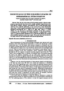
length of 2 lm was analyzed for every fin in the quadruplet. The average of the local line width corresponds to the CD. For the LWR a full spectral analysis is integrated [11] in the software since the 3sigma of the CD is not sufficient to define the LWR. The CD of the fins after etch is 17 nm in the center of the wafer and 18 nm in a die at the edge. This indicates that the TEOS oxide film was deposited and etched with good uniformity. The LWR is 3 nm and independent of the position on the wafer. After fin patterning typically an oxidation and H2 anneal is applied for sidewall smoothening and rounding of the fin top corners [12]. We have investigated the influence on CD and LWR after 2 nm thermal oxidation at 700 °C followed by an H2anneal at 900 °C. We found that CD decreases to 13 nm in the center of the wafer and that the LWR does not change (Fig. 10). The latter observation needs some explanation. The LWR value of 3 nm is obtained by analyzing the local line width of all four lines from the quadruplet. We have also made the analysis separately on the inner and outer fins (with inner fins we refer to the two middle fins of the quadruplet, see Fig. 7a). The average CD of the inner fins is 17 nm and 16 nm for the outer fins. This CD difference is caused by the sidewall slope of the SiGe sacrificial hard mask (Fig. 3b). Because the profile is not perfectly straight (i.e. 88°) the nitride spacer pattern is positively sloped on one side and negatively sloped on the other side (Fig. 4c). The TEOS spacer pattern that is defined on the positively sloped nitride spacer results in a Si-fin with smaller CD compared to the TEOS spacer that is defined on the negative slope. For the LWR no major differences were observed: 2.5 nm was found for both the inner and outer fins. These values show that the overall LWR of the quadruplet is governed by the difference in CD between inner and outer fins rather than the local line width variation for one line. The separate analysis on inner and outer fins was also done for the images obtained after oxidation and H2 anneal. We find an average CD of 14 nm for the inner fins and 13 nm for the outer fins. In both cases the LWR was 2.1 nm. This shows that even though the overall LWR of the quadruplet does not change, the line width variation on a single line decreases with about 10% after oxidation and H2 anneal. In resist-defined patterning, LER originates from lithography and etch. This results in random-uncorrelated LER on the fin sidewalls which causes local fin width fluctuations along the fin length. In spacer-defined patterning, LER pattern gets transferred from resist to a dummy spacer. This results in an in-phase correlation of randomLER on the fin sidewalls and reduces the LWR with 50%. Top down SEM images of resist and spacer defined fins are shown in Fig. 11 to illustrate physical impact of LER- correlation. Simulations reveal that spacer-defined fin devices have potential to achieve superior intrinsic matching performance due to in-phase correlation of the fin LER [13].
pe
rs
Fig. 7. XSEM images after complete patterning and TEOS spacer removal for a dummy SOI wafer. (a) The sample was cleaved through a straight line pattern where no S/D pads are defined. The original SiGe lines used as sacrificial HM were 80 nm wide with a pitch of 350 nm. The TEOS spacer pattern was removed in 0.3% HF. Fin 1 and 4 of the quadruplet are referred to as outer fins, 2 and 3 inner fins. (b) Tilted view of Si-fins formed SiGe oval shapes (no S/D pad defined). The sample was cleaved in between two fins separated by only 30 nm.
common S/D pad. In the next section we focus on the CD performance and the LWR of the spacer defined fins.
r's
3.2. Critical dimension (CD) and line width roughness (LWR)
Au
th o
CD and LWR analysis was done for long lines of fin quadruplets. Top down SEM images of the fins were created with the XL810 microscope from FEI and analyzed offline. A VLSI standard wafer with alternating a-Si and oxide layers (Fig. 8a) is used to calibrate the CD measurements of top-Down SEM algorithm and offline software threshold, resulting in accurate and reproducible measurements (Fig. 8b). In order to extract the CD and LWR data from the SEM images the software program Lerdemo from Demokritos was used. Before delivering the images to Lerdemo an image pixel treatment is done by an in-house developed MatlabÒ program (Fig. 9). With this treatment the value of the center pixels from a line are replaced by a zero to avoid that the outer edges of two lines are considered as the edges of one line. As output Lerdemo gives the mean CD and the LWR of the lines. For each pixel line (perpendicular to the fin) the line edges are detected (see arrows in Fig. 9d) and the local line width is calculated. A total line
615
616
B. Degroote et al. / Microelectronic Engineering 84 (2007) 609–618
(a) α-Si
140nm
oxide
105nm
50nm 30nm 13nm
co
15nm
py
75nm
c-Si
(b) 160 y = 1.0315x + 5.515 R2 = 0.9998
al
120 100 80 60
on
CD SEM (nm)
140
40 20 0
20
40
60
rs
0 80
100
120
140
160
CD TEM (nm)
Au
th o
r's
pe
Fig. 8. HR TEM image (a) of a VLSI standard wafer with alternating a-Si and oxide layers used to calibrate the CD measurements of top-Down SEM algorithm (b) and offline software threshold.
Fig. 9. Demonstration of the image treatment necessary for CD and LWR analysis. (a) The original SEM image. (b) The image after treatment: the pixels in the center of the lines are set to zero. (c) and (d) SEM intensity profile before and after treatment. The profile shown corresponds to the average of the pixel lines perpendicular to the fin. For CD and LWR analysis each pixel line is taken independently. The arrows point at locations that are recognized as a line edge by the Lerdemo program from Demokritos.
617
py
B. Degroote et al. / Microelectronic Engineering 84 (2007) 609–618
co
Fig. 10. Top down SEM images after complete patterning and TEOS spacer removal for a real SOI wafer. (a) Before oxidation and H2 anneal the inner fin CD is 17 nm with a LWR of 2.5 nm. (b) After CR and H2 anneal the inner fin CD is reduced to 14 nm with a LWR of 2.1 nm.
al
pe
rs
Alternatively, to continue with resist-defined fins, reduction in LER-amplitude is required to improve matching performance and avoid local discontinuities in narrow fins (WFIN = 10 nm).
on
Fig. 11. SEM image of (a) resist- and (b) spacer-defined fin. Random LERs on fin sides are uncorrelated and correlated-in-phase for resist- and spacer-defined fins respectively.
Si-fin quadruplets with the SiON spacer pattern as a hard mask has been demonstrated. The next issue we want to address is whether S/D pads are really necessary. If they are skipped, we can reduce the number of process steps. We have done experiments where the SOI layer was patterned only with the TEOS spacer pattern without resist based S/D pattern. We found no difference in terms of CD, LWR and fin profile compared to the process with S/D pattern. However, using S/D pads is definitely beneficial for fin stability (at least when the fin length is limited below 500 nm). In addition, if the fins of the same transistor are not connected at active level by S/ D pads, the design rules of the active area patterning need to be matched to the design rules of the contact level (one contact hole for every fin quadruplet). This means that from process point of view the use of S/ D pads has important advantages. On the other hand, the effect on device performance still needs to be investigated.
3.3. Process issues
Au
th o
r's
In this Section three process issues are discussed: fin stability, the use of S/D pads and alignment. Fin stability is definitely a concern for the small CD’s reported here. The removal of the TEOS spacer pattern after patterning the SOI layer already results in a BOX recess of 4.5 nm. After oxidation another 2 nm of thermal oxide needs to be removed. This adds up to a BOX recess of 6.5 nm (without taking the gate pre-clean into account). As the fin undercut increases with increasing HF exposure time, instability of fins not connected by S/D pads can become an issue. The BOX recess can be reduced by using SiON instead of TEOS for the final spacer pattern. From dry etch point of view (etch rate, selectivity, etc.) SiON is behaving quite similar as SiO2 but the advantage is that it can be removed in hot H3PO4 acid with a high selectivity towards the BOX. We have already performed experiments with a PECVD SiON layer deposited on the nitride spacer pattern. The deposition was done on a Centura Platform from Applied Materials and the SiON layer contains about 10% of nitrogen. We found that the SiON spacers can be etched with the same CF4/CH2F2 based chemistry that is used for the TEOS spacer etch resulting in a similar profile. The nitride spacer pattern can also be removed selectively to the SiON spacer pattern with a CH3F/O2/CF4 plasma. Patterning of
4. Conclusions We have successfully demonstrated a method to obtain Si-fins with CD below 20 nm, separated by a minimum distance of 30 nm and connected by a common S/D pad. CD and Line Width Roughness (LWR) analysis was done on top down SEM images taken in a center die and in an edge die of a 200 mm wafer. The average CD is 17 nm in the center of the wafer and 18 nm at the edge. This proves that spacer defined patterning is a viable method to obtain a high pattern density with good CD uniformity. The LWR is of the order of 3 nm and is uniform over the wafer. The overall LWR of a fin quadruplet is governed by the difference in CD between the inner and the outer fins. This CD difference can be minimized by optimizing the profile of the sacrificial hard mask. After oxidation and H2 anneal the CD was reduced to 13 nm. The described method is suitable for integration in 3D MuGFET devices. References [1] D. Hisamoto, W.C. Lee, J. Kedzierski, H. Takeuchi, K. Asano, C. Kuo, E. Anderson, T.J. King, J. Bokor, C.M. Hu, IEEE Trans. Electron Dev. 47 (2000) 2320. [2] N. Collaert, A. Dixit, M. Goodwin, K.G. Anil, R. Rooyackers, B. Degroote, P. Leunissen, A. Veloso, R. Jonckheere, K. De Meyer, M. Jurczak, S. Biesemans, IEEE Electron Dev. Lett. 25 (2004) 568.
618
B. Degroote et al. / Microelectronic Engineering 84 (2007) 609–618 [8] F.S. Johnson, D.S. Miles, D.T. Grider, J.J. Wortman, J. Electron. Mater. 21 (1992) 805. [9] K.G. Anil et al., Symp. VLSI Tech. (2005) 198. [10] D. Shamiryan et al., J. Vac. Sci. Technol. B 23 (5) (2005) 2194. [11] P.H.A. Leunissen, G.F. Lorusso, M. Ercken, J.A. Croon, H. Yang, A. Azordegan, C. Delvaux, N. Vandenbroeck, F. Van Roey, T. DiBiase, SPIE 5752 (2005) 499. [12] W. Xiong et al., IEEE Electron Dev. Lett. 25 (2004) 541. [13] A. Dixit et al., IEDM Techn. Digest, 2006.
Au
th o
r's
pe
rs
on
al
co
py
[3] L. Witters et al., Symp. VLSI Tech. (2005) 106. [4] K.G. Anil, K. Henson, S. Biesemans, N. Collaert, Proc. ESSDERC’03 (2003) 139. [5] Y.-K. Choi, T.-J. King, C. Hu, IEEE Trans. Electron Dev. 49 (2002) 436. [6] Y.-K. Choi, T.-J. King, C. Hu, IEEE Electron Dev. Lett. 23 (2002) 25. [7] Y.-K. Choi, J. Zhu, J. Grunes, J. Bokor, G.A. Somorjai, J. Phys. Chem. B 107 (2003) 3340.