Influence of photosensor noise on accuracy of cost-effective Shack-Hartmann wavefront sensors M OTIVATION
AND
G OALS
Mikhail V. Konnik James Welsh School of Electrical Engineering and Computer Science The University of Newcastle, Australia M ODEL
OF THE
S HACK -H ARTMANN WAVEFRONT
SENSOR
Using comprehensive model of a photosensor, new results in numerical simulations and analysis of cen- The Shack-Hartmann wavefront sensor was simulated with the parameters: troiding accuracy for the cost-effective CMOS-based wavefront sensors were elaborated: ◮ 32 × 32 lenslets, 32 × 32 pixels per lenslet; ◮ analysis of influence of different noise sources from the CMOS photosensor on the centroiding ◮ photosensor in the WFS has 5.00µm pixels with the pixel fill factor of 50%, quantum efficiency of 60%, robustness in the Shack-Hartmann wavefront sensor is presented; and full well of 20000 e −; − ◮ influence of light and dark noises as well as pixelisation factor has been assessed. ◮ surrounding temperature is 300K, the sense node gain is 5.00 µV /e , and clock speed is 20 MHz. Numerical experiments are aimed in study of a cost-effective wavefront sensor, and for that reason, ´ an ´ power Such parameters are typical for a cost-effective CMOS-based wavefront sensor. The von Karm we simulate CMOS sensors using previously developed high-level model. spectrum model for the turbulence was used. The size of turbulence layer is 1024 × 1024 pixels.
N UMERICAL S IMULATION R ESULTS :
LENSLET FOCAL LENGTH AND PIXELISATION ERROR INFLUENCE ON WAVEFRONT SENSOR ACCURACY
Lenslet focal length
Pixelisation error Conditions of the numerical experiment: ◮ observation wavelength λ = 0.5µm; ◮ diameter of the lenslet Dlenslet = 200µm; ◮ typical values for the focal distance of the lenslets in the Shack-Hartmann lenslet are 10-20 mm; ◮ the focus distance of the lenslet from 1 mm to 50 mm with the step of 1 mm.
Conditions of the numerical experiment: ◮ the amount of pixels in each lenslet was varied from 64 × 64 (initial size) down to 4 × 4 pixels with step of 4 pixels; ◮ size of the lenslet remains constant; ◮ the centroiding coordinates were calculated using a simple CoG algorithm both for the original centroiding image.
Results: The centroid position can be
Results: The pixelisation error grows
effectively measured using the lenslets with focal distance no more than 20-30 mm. Increasing the focus length further gives no improvements over the accuracy of centroiding. This is consistent with typical values of 7-10 mm focal length of the lenslets in Shack-Hartmann sensor.
slowly when the number of pixels in the lenslet shrinks from 64 × 64 to 32 × 32 pixels. The pixelisation error in this case is ∆xrms ≈ 0.002, or 0.2% rms.
N UMERICAL S IMULATION R ESULTS :
The growth of the pixelisation error increases: for the case of 12 × 12 pixels in the lenslet one can observe an abrupt increase of the pixelisation error to ∆xrms ≈ 0.006 − 0.007, which is 3 times larger than for the case 32 × 32 pixels in the lenslet.
CENTROIDING ERROR CAUSED BY THE PHOTON SHOT NOISE
Photon shot noise influence on accuracy
Probability density of centroiding errors due to shot noise
Conditions of the numerical experiment: ◮ 32 images of the centroids were generated given the same turbulence realisation; ◮ the standard deviation of the centroids coordinates was calculated in the number of pixels; ◮ results of the photon shot noise influence are presented as the percentage of the centroid’s coordinate.
Results:
As the integration time increases, the shot noise increases proportionally. However, in different lenslets, centroids are different; hence, the dependency may look different. The analysis of the data allows to say that the influence of shot noise is from 0.2% to 1.5% of pixel.
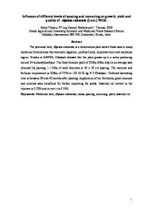
N UMERICAL S IMULATION R ESULTS :
a)
c)
Figure: Estimation of centroids measurement distribution for the case of the photon shot noise only: a) low-light (600 e −), b) intermediate light conditions (3500 e −), and c) high light (13500 e −).
The photon shot noise in these numerical experiments was the only one turned on. The integration time and PRNU factor were fixed, and 1000 frames from the simulated SH WFS were taken.
Results: The results are consistent with assumptions that the centroiding errors in the case of dominance of the photon shot noise are Gaussian.
CENTROIDING ERROR CAUSED BY THE
PRNU noise influence on accuracy
b)
PRNU
NOISE
Probability density of centroiding errors due to PRNU noise Conditions of the numerical experiment: ◮ 32 images were of the centroids generated with the same turbulence; ◮ the standard deviation of the centroids coordinates was calculated in the number of pixels; ◮ the PRNU factor was 1%, 2% and 5%;
Results: The increase of the PRNU factor from 1% to 2% also increases the centroiding error, especially in low-light area (below 3000 electrons). The increase of the centroiding error from 0.3 . . . 0.6 % in low-level area of measurements up to 0.4 . . . 0.9 %. Further increase of the PRNU factor to 5% shows the increase of the centroiding errors to 0.9 . . . 1.7 %, which makes the wavefront estimation difficult. The exact behaviour of errors in different lenslets may differ, but the overall influence is similar.
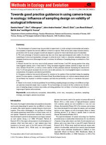
N UMERICAL S IMULATION R ESULTS : ADC QUANTISATION
CENTROIDING ERROR CAUSED BY
a)
b)
c)
Figure: Estimation of centroids coordinates distribution for the case of the photon shot noise and the PRNU of factor 1% for: a) low-light (600 e −), b) intermediate light conditions (3500 e −), and c) high light (13500 e −).
Results: the distribution of centroids coordinates tends to drift from Gaussian-alike in case of low illumination to non-symmetrical distribution in case of high illumination level. That is, the assumption that in case of shot noise the centroiding error can be modelled as Gaussian is generally correct; however, for the case of the intermediate illumination the distribution is non-symmetrical that may lead to inaccurate results.
C ONCLUSIONS
1. assuming that WFS has 64 × 64 pixels per lenslet, the pixelisation error is shown to grow slowly until the amount of pixels in lenslets are half of original (causes the error of 0.2% rms); To compare the influence of the ADC, we turned on the photon shot noise, the PRNU with the factor 1%, the dark current with the dark current figure of merit DR = 0.5nA/cm2 on temperature T=300K, the dark 2. the pixelisation error increases abruptly to 0.7% rms (3 times increase) when the number of pixels in the current shot noise and the dark FPN of factor 25%. lenslet is a quarter of the original amount. Table: Quantisation error caused by the finite ADC resolution (error is given in percent of a pixel).
Light conditions Double precision (no quantisation) mean max error error Low light level 5.2% 8.1% Mid level of light 3.9% 4.3% High level of light 3.5% 4.1%
12 bit quantisation mean max error error 6.4% 12.8% 4.4% 5.2% 3.9% 4.2%
10 bit quantisation mean max error error 22.6% 32.1% 7.8% 5.4% 4.6% 5.0%
8 bit quantisation mean max error error 35.9% 65.2% 10.3% 14.4% 6.4 7.2%
Results: the quantisation errors produced by 10-bit ADC introduces mean error in centroids coordinates
3. the centroiding errors caused by photon shot noise only and for the case of shot noise and PRNU is of the same order (up to 1.5% of pixel). 4. the PRNU influence on the centroiding accuracy for the PRNU factor of 5%, 2% and 1% is 0.9 . . . 1.7 % of pixel, 0.4 . . . 0.9 % of pixel and 0.3 . . . 0.6 % of pixel, respectively. 5. the results for quantisation errors show that the 10-bit ADCs, which are frequently used in cost-effective WFS, may be considered as a sub-optimal solution. 6. in low-light conditions, the mean error in centroids coordinates for 10 bit ADC is of 22%, whenever for the 12-bit ADC the mean error is only 6%.
of 22% in low-light conditions. The ADC with 12 bit resolution should be used in cost-effective WFS instead 7. for the photon shot noise and PRNU, the distribution of centroids errors tends to drift from the Gaussian-alike to the non-symmetrical distribution. of commonly used 10-bit ADCs.