Code No: NR220304
NR
Set No. 2
II B.Tech II Semester Supplementary Examinations,May 2010
1. (a) Explain the gears used for Parallel Shafts with neat sketches?
in
KINEMATICS OF MACHINES / MECHANICS OF MACHINERY Common to Mechanical Engineering, Mechatronics, Production Engineering, Aeronautical Engineering Time: 3 hours Max Marks: 80 Answer any FIVE Questions All Questions carry equal marks ?????
ld .
(b) The velocity ratio of two spur gears in mesh is 0.4 and the centre distance is 75 mm. For a module of 1.2 mm, find the number of teeth of gears. What will the pitch line velocity if the pinion speed is 800 rpm? Also find the speed of the gear wheel. [6+10]
or
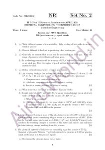
2. In a mechanism as shown in Figure 3, the link AB rotates with a uniform angular velocity of 30 rad/S. The lengths of various links are; AB = 100mm; BC = 300 mm; BD = 150 mm; DE = 250 mm; EF = 200 mm; DG=165 mm.
[16]
Aj
nt
uW
Determine the velocity and acceleration of G for the given configuration.
Figure 3
3.a) What are various approximate straight line motion mechanisms? b) Explain Watt’s Straight line mechanism. What are the pratical uses of this mechanism? [4+12]
4. What is the difference between quick return motion of crank and slotted lever type and that of Whitworth type? What is the ratio of time taken on cutting and return strokes? [16] 1
Code No: NR220304
NR
Set No. 2
5. Derive equations to describe the displacement diagram of a cam which rises with parabolic motion from a dwell to another dwell such that the total lift is L and total cam rotation angle is ß Plot the displacement diagram and its first three derivatives with respect to cam rotation. [16]
in
6. In a Whitworth quick return motion, a crank AB rotates about the fixed center A. The end B operates a slider reciprocating in a slotted link, rotating about a fixed center D, 5 cm vertically above A. The crank AB which is 10 cm long, rotates in a clockwise direction at speed of 100 rpm. Find the angular acceleration of a slotted link for the configuration in which AB has turned through an angle of 45 degrees past its lowest position. [16]
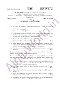
Figure 5
Aj
nt
uW
or
ld .
7. Figure 5 shows diagrammatically a compound epicycic gear train. Wheels A, D and E are free to rotate independently on spindle O, While B, C are compounded and rotate together on spindle P, on the end of arm OP. All the wheels have teeth of the same pitch, A has 12 teeth, B has 30 and C has 14 teeth cut externally. Find the number of teeth on wheels D and E which are cut internally. If the wheel A is driven clockwise at 1 rps, while D is driven counter clockwise at 5 rps, determine the magnitude and direction of the angular velocities of arm OP and wheel E. [16]
8. The driving shaft of Hook’s joint runs at a uniform speed of 250 rpm and the angle between the shaft axes is 250 , the driven shaft with attached masses has a weight of 54.5 Kg at a radius of gyration of 15.25Cm. If a steady torque of 2000 Kg-cm resists rotation of the driven shaft, find the torque required at the driving shaft when it rotates 450 . [16] ?????
2
Code No: NR220304
NR
Set No. 4
in
II B.Tech II Semester Supplementary Examinations,May 2010 KINEMATICS OF MACHINES/MECHANICS OF MACHINERY Common to Mechanical Engineering, Mechatronics, Production Engineering, Aeronautical Engineering Time: 3 hours Max Marks: 80 [4+12] Answer any FIVE Questions All Questions carry equal marks ?????
ld .
1. The driving shaft of Hook’s joint runs at a uniform speed of 250 rpm and the angle between the shaft axes is 250 , the driven shaft with attached masses has a weight of 54.5 Kg at a radius of gyration of 15.25Cm. If a steady torque of 2000 Kg-cm resists rotation of the driven shaft, find the torque required at the driving shaft when it rotates 450 . [16]
or
2. In a mechanism as shown in Figure 3, the link AB rotates with a uniform angular velocity of 30 rad/S. The lengths of various links are; AB = 100mm; BC = 300 mm; BD = 150 mm; DE = 250 mm; EF = 200 mm; DG=165 mm.
[16]
nt
uW
Determine the velocity and acceleration of G for the given configuration.
Aj
Figure 3 3.a) What are various approximate straight line motion mechanisms? b) Explain Watt’s Straight line mechanism. What are the pratical uses of this mechanism?
4. In a Whitworth quick return motion, a crank AB rotates about the fixed center A. The end B operates a slider reciprocating in a slotted link, rotating about a fixed center D, 5 cm vertically above A. The crank AB which is 10 cm long, rotates in a 3
Code No: NR220304
NR
Set No. 4
clockwise direction at speed of 100 rpm. Find the angular acceleration of a slotted link for the configuration in which AB has turned through an angle of 45 degrees past its lowest position. [16]
in
5. Derive equations to describe the displacement diagram of a cam which rises with parabolic motion from a dwell to another dwell such that the total lift is L and total cam rotation angle is ß Plot the displacement diagram and its first three derivatives with respect to cam rotation. [16]
ld .
6. What is the difference between quick return motion of crank and slotted lever type and that of Whitworth type? What is the ratio of time taken on cutting and return strokes? [16] 7. (a) Explain the gears used for Parallel Shafts with neat sketches?
or
(b) The velocity ratio of two spur gears in mesh is 0.4 and the centre distance is 75 mm. For a module of 1.2 mm, find the number of teeth of gears. What will the pitch line velocity if the pinion speed is 800 rpm? Also find the speed of the gear wheel. [6+10]
Aj
nt
uW
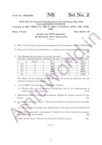
8. Figure 5 shows diagrammatically a compound epicycic gear train. Wheels A, D and E are free to rotate independently on spindle O, While B, C are compounded and rotate together on spindle P, on the end of arm OP. All the wheels have teeth of the same pitch, A has 12 teeth, B has 30 and C has 14 teeth cut externally. Find the number of teeth on wheels D and E which are cut internally. If the wheel A is driven clockwise at 1 rps, while D is driven counter clockwise at 5 rps, determine the magnitude and direction of the angular velocities of arm OP and wheel E. [16]
Figure 5 ?????
4
Code No: NR220304
NR
Set No. 1
1. (a) Explain the gears used for Parallel Shafts with neat sketches?
in
II B.Tech II Semester Supplementary Examinations,May 2010 KINEMATICS OF MACHINES/MECHANICS OF MACHINERY Common to Mechanical Engineering, Mechatronics, Production Engineering, Aeronautical Engineering Time: 3 hours Max Marks: 80 Answer any FIVE Questions All Questions carry equal marks ?????
ld .
(b) The velocity ratio of two spur gears in mesh is 0.4 and the centre distance is 75 mm. For a module of 1.2 mm, find the number of teeth of gears. What will the pitch line velocity if the pinion speed is 800 rpm? Also find the speed of the gear wheel. [6+10]
or
2. In a mechanism as shown in Figure 3, the link AB rotates with a uniform angular velocity of 30 rad/S. The lengths of various links are; AB = 100mm; BC = 300 mm; BD = 150 mm; DE = 250 mm; EF = 200 mm; DG=165 mm.
[16]
Aj
nt
uW
Determine the velocity and acceleration of G for the given configuration.
Figure 3
3. In a Whitworth quick return motion, a crank AB rotates about the fixed center A. The end B operates a slider reciprocating in a slotted link, rotating about a fixed center D, 5 cm vertically above A. The crank AB which is 10 cm long, rotates in a clockwise direction at speed of 100 rpm. Find the angular acceleration of a slotted link for the configuration in which AB has turned through an angle of 45 degrees past its lowest position. [16]
4. Derive equations to describe the displacement diagram of a cam which rises with parabolic motion from a dwell to another dwell such that the total lift is L and total 5
Code No: NR220304
NR
Set No. 1
in
cam rotation angle is ß Plot the displacement diagram and its first three derivatives with respect to cam rotation. [16] 5.a) What are various approximate straight line motion mechanisms? b) Explain Watt’s Straight line mechanism. What are the pratical uses of this mechanism? [4+12] 6.What is the difference between quick return motion of crank and slottedle vertype and that of Whitworthtype?Whatistheratiooftimetakenoncuttingandreturn strokes?[16]
Aj
nt
uW
or
ld .
7. Figure 5 shows diagrammatically a compound epicycic gear train. Wheels A, D and E are free to rotate independently on spindle O, While B, C are compounded and rotate together on spindle P, on the end of arm OP. All the wheels have teeth of the same pitch, A has 12 teeth, B has 30 and C has 14 teeth cut externally. Find the number of teeth on wheels D and E which are cut internally. If the wheel A is driven clockwise at 1 rps, while D is driven counter clockwise at 5 rps, determine the magnitude and direction of the angular velocities of arm OP and wheel E. [16]
Figure 5
8. The driving shaft of Hook’s joint runs at a uniform speed of 250 rpm and the angle between the shaft axes is 250 , the driven shaft with attached masses has a weight of 54.5 Kg at a radius of gyration of 15.25Cm. If a steady torque of 2000 Kg-cm resists rotation of the driven shaft, find the torque required at the driving shaft when it rotates 450 . [16]
?????
6
Code No: NR220304
NR
Set No. 3
in
II B.Tech II Semester Supplementary Examinations,May 2010 KINEMATICS OF MACHINES/MECHANICS OF MACHINERY Common to Mechanical Engineering, Mechatronics, Production Engineering, Aeronautical Engineering Time: 3 hours Max Marks: 80 [4+12] Answer any FIVE Questions All Questions carry equal marks ?????
ld .
1. The driving shaft of Hook’s joint runs at a uniform speed of 250 rpm and the angle between the shaft axes is 250 , the driven shaft with attached masses has a weight of 54.5 Kg at a radius of gyration of 15.25Cm. If a steady torque of 2000 Kg-cm resists rotation of the driven shaft, find the torque required at the driving shaft when it rotates 450 . [16] 2. (a) Explain the gears used for Parallel Shafts with neat sketches?
or
(b) The velocity ratio of two spur gears in mesh is 0.4 and the centre distance is 75 mm. For a module of 1.2 mm, find the number of teeth of gears. What will the pitch line velocity if the pinion speed is 800 rpm? Also find the speed of the gear wheel. [6+10]
uW
3. In a mechanism as shown in Figure 3, the link AB rotates with a uniform angular velocity of 30 rad/S. The lengths of various links are; AB = 100mm; BC = 300 mm; BD = 150 mm; DE = 250 mm; EF = 200 mm; DG=165 mm. [16]
Aj
nt
Determine the velocity and acceleration of G for the given configuration.
Figure 3 4.a) What are various approximate straight line motion mechanisms? b) Explain Watt’s Straight line mechanism. What are the pratical uses of this mechanism? [4+12]
Code No: NR220304
NR
Set No. 3
uW
or
ld .
in
5. Figure 5 shows diagrammatically a compound epicycic gear train. Wheels A, D and E are free to rotate independently on spindle O, While B, C are compounded and rotate together on spindle P, on the end of arm OP. All the wheels have teeth of the same pitch, A has 12 teeth, B has 30 and C has 14 teeth cut externally. Find the number of teeth on wheels D and E which are cut internally. If the wheel A is driven clockwise at 1 rps, while D is driven counter clockwise at 5 rps, determine the magnitude and direction of the angular velocities of arm OP and wheel E. [16]
Figure 5
nt
6. Derive equations to describe the displacement diagram of a cam which rises with parabolic motion from a dwell to another dwell such that the total lift is L and total cam rotation angle is ß Plot the displacement diagram and its first three derivatives with respect to cam rotation. [16]
Aj
7. In a Whitworth quick return motion, a crank AB rotates about the fixed center A. The end B operates a slider reciprocating in a slotted link, rotating about a fixed center D, 5 cm vertically above A. The crank AB which is 10 cm long, rotates in a clockwise direction at speed of 100 rpm. Find the angular acceleration of a slotted link for the configuration in which AB has turned through an angle of 45 degrees past its lowest position. [16] 8. What is the difference between quick return motion of crank and slotted lever type and that of Whitworth type? What is the ratio of time taken on cutting and return strokes? [16]
?????
8