Routability Enhancement through Unidirectional Standard Cells with Floating Metal-2 Jaewoo Seoab and Youngsoo Shina a School
of Electrical Engineering, KAIST, Daejeon 34141, Korea b Samsung Electronics, Hwasung 18448, Korea ABSTRACT
Bidirectional cell refers to a standard cell, in which metal-1 is used for both horizontal and vertical connections. Unidirectional cell, on the other hand, assumes reserved routing, e.g. metal-1 for only horizontal and metal-2 for only vertical connections. It has been introduced to take advantage of regular metal patterns, which are easier to print and can overcome the lithography limitations in sub-32nm technology. In unidirectional cell, metal-2 is laid out following the cell placement pitch. Since metal-2 pitch is usually different from placement pitch, some within-cell metal-2 become off track. This significantly degrades metal-2 routability. We propose a unidirectional cell with floating metal-2. After initial cell placement, metal-2 segment within each cell is snapped to nearest metal-2 track and is fixed. In addition, we propose cell redesign and post-placement optimization to enhance metal-1 routability. Metal-1 connections are forced to populate in limited number of tracks, so that remaining tracks are exposed during routing. Combined with post-placement optimization, this allows many longer metal-1 tracks to be available for horizontal connection. Experiments with test circuits show that routing errors are reduced by 7% and 60% with the proposed metal-1 considerations and floating metal-2 together. Keywords: Unidirectional cell, Standard cell layout, Floating metal
1. INTRODUCTION In sub-32nm process, lithography limitations are becoming critical in relation to the continued efforts to scale down semiconductor technology. According to Rayleighs criteria, a smaller optical wavelength is required to manufacture a smaller feature size. However, optical wavelength scaling is not easy. Since the 193nm ArF light source was introduced in 2003,1 despite the many studies which have since been conducted, a viable alternative light source remains elusive. Extreme ultraviolet (EUV) light is arising as the most promising solution due to its short wavelength of 13.5nm; nevertheless, EUV lithography is delayed as a result of its low productivity. For this reason, 193nm ArF lithography is still widely used in the sub-32nm process with sophisticated mask engineering methods such as immersion2 and multiple-patterning3 lithography. The unidirectional design was introduced to overcome the wavelength scaling lithography limitation.4–6 Figure 1 shows bidirectional and unidirectional cell layouts for a NAND2 cell. As shown in the figure, the bidirectional cell uses both vertical and horizontal metal-1. However, in the unidirectional cell, horizontal metal-1 and vertical metal-2 are used for only one direction. Therefore, compared to a conventional bidirectional layout, the unidirectional cell shows an extremely simple and regular layout pattern. Given this simplicity and regularity, the unidirectional layout can achieve a smaller feature size without wavelength scaling in the light source.7, 8 Industry has started to use the unidirectional design, as evidence by the use of a poly-layer in the 65nm SRAM design.6 Moreover, at present, research on unidirectional designs extends to standard cell design for which not only a poly-layer but also metal layers are used.4, 7–12 Although unidirectional cells are easier to manufacture, they have metal-2 routability limitation. As shown in Figure 2(a), cell is designed and placement is performed using poly pitch. During routing, however, metal-2 connection is made using metal pitch, which is typically less than poly pitch. Due to this mismatch between poly and metal pitch, some within-cell metal-2 segments become off-track (see Figure 2(b)). This off-track metal-2 significantly degrades metal-2 routability. For instance, in Figure 2(c), 8 metal-2 tracks are available, but each internal metal-2 segment that is off-track blocks 2 tracks; therefore, only 4 tracks are used for routing and the remaining 4 tracks are wasted.
Design-Process-Technology Co-optimization for Manufacturability XI, edited by Luigi Capodieci, Jason P. Cain, Proc. of SPIE Vol. 10148, 101480K · © 2017 SPIE CCC code: 0277-786X/17/$18 · doi: 10.1117/12.2258010 Proc. of SPIE Vol. 10148 101480K-1 Downloaded From: http://proceedings.spiedigitallibrary.org/ on 04/02/2017 Terms of Use: http://spiedigitallibrary.org/ss/termsofuse.aspx
Poly pitch cell grid Poly
VDD
Via-1
VDD M2
B
A
Y
Y M1
B
VSS A VSS
(a)
(b)
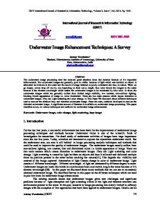
Figure 1. (a) Bidirectional and (b) unidirectional cell layout for NAND2. Poly pitch cell placement
Metal pitch routing tracks
Off-track M2 (a)
8 tracks
4 valid tracks
(b)
(c)
Figure 2. (a) Cell placement in poly pitch, (b) off-track M2 caused by mismatch between poly- and M2-pitch, and (c) corresponding routability degradation.
To avoid the off-track problem, previous researchers increased the metal-2 routing pitch up to poly pitch (see Figure 3(a)).4, 8–10, 12 Because within-cell metal-2 is unmovable, instead, the routing track pitch is increased. However, the increased routing pitch removed 25-36%4, 9 of the metal-2 routing tracks, which cannot ideally resolve the metal-2 routability degradation, as shown in Figure 3(b); 6 tracks are used for routing instead of 8 tracks.
2. UNIDIRECTIONAL STANDARD CELL WITH FLOATING M2 2.1 Floating M2 We present a new concept of a layer in this paper, i.e., floating metal. In our proposed solution, within-cell metal-2 segment is assumed floating. For traditional layers in a standard cell layout, the within-cell metal-2 position is fixed with the cell layout and the designer cannot change the layer position. However, we present a new layer which allows changes in its position. Floating metal is used in the cell layout, but its location can move during certain design steps. Floating metal is effective to enhance metal-2 routability in a unidirectional design. As shown in Figure 3(c), once placement is performed and all metal-2 tracks are identified, each metal-2 segment is snapped to nearest metal-2 track. Therefore, an increase of the metal-2 routing track pitch is not required due to the use of the proposed floating metal-2, and the routing pitch remains a metal pitch.
Proc. of SPIE Vol. 10148 101480K-2 Downloaded From: http://proceedings.spiedigitallibrary.org/ on 04/02/2017 Terms of Use: http://spiedigitallibrary.org/ss/termsofuse.aspx
6 tracks
Metal pitch poly pitch
Metal pitch
Snapped to nearest routing track
On-track M2 (a)
(b)
(c)
Figure 3. (a) Poly pitch based M2 routing tracks, (b) on-track M2 routing, and (c) proposed floating M2. M1 extension for floating M2
Whalf
Shalf
Dmax
(a)
(b)
Figure 4. (a) M1 extension for flexible M2 movement and (b) maximum distance that floating M2 can move.
2.2 Cell Layout Redesign for Floating M2 Standard cell layout should be redesigned to allow the snap. In particular, horizontal metal-1 should be extended wherever possible for better flexibility of metal-2 movement. As shown in Figure 4(a), the floating metal cannot move when metal-1 is not extended sufficiently. If the metal-2 in the figure moves to the left and right sides, the metal-1 and via-1 overlap design rule violation will occur, resulting in a design failure. Therefore, as shown in Figure 4(a), metal-1 should be extended appropriately. We present the maximum floating metal-2 moving distance as follows, Dmax = Whalf + Shalf ,
(1)
where Dmax is the maximum floating metal-2 moving distance, Whalf is half of the metal-2 wire width, and Shalf is half of the metal-2 wire space as shown in Figure 4(b). Therefore, Dmax is equal to half the metal pitch. Unidirectional cells should be redesigned to use the proposed floating metal, and metal-1, with a connection to floating metal-2, should be properly extended with the parameter Dmax .
3. CONSIDERATIONS ON M1 ROUTABILITY 3.1 Cell Layout Redesign for M1 Routability We also consider metal-1 routability in a unidirectional design. Metal-1 routing can be used in unidirectional designs. For the bidirectional cell layout, vertical within-cell metal-1 prevents the use of metal-1 over the cell routing. However, unlike the bidirectional cell layout, the unidirectional cell contain only horizontal metal-1 wires, and metal-1 routing wires can penetrate the cells if the cells have empty metal-1 track lines.
Proc. of SPIE Vol. 10148 101480K-3 Downloaded From: http://proceedings.spiedigitallibrary.org/ on 04/02/2017 Terms of Use: http://spiedigitallibrary.org/ss/termsofuse.aspx
Track 7
M1 channel
Power rail B
Track 6
VDD
Track 5
High priority
Low priority
Track 4 Track 3
VDD
Y
A
VDD
Y
A
A
VDD
B
Y
A
Y
Track 2 VSS
VSS
VSS
VSS
Ground rail
Track 1
(a)
(b)
Figure 5. (a) Proposed priority of M1 track usage and (b) cell layout redesign with assumed priority.
C1
C1F
...
Ci-1
Ci
Ci+1
...
Cn
Ci-1
Ci
Ci-2F
Ci-1F
CiF
Ci-1
Ci
Ci+1
...
s
C1
Ci-2
Cn-1
Cn-1F ...
t
C2
Ci-1F
CiF
Ci+1F
Cn
C2F
Ci
Ci+1
Ci+2
CnF
CiF
Ci+1F
Ci+2F
(a)
(b)
Figure 6. (a) Cell sequence in a standard cell row and (b) graph representation for cell flip and swap.
Because longer empty metal-1 tracks are useful to horizontal routing and can be fabricated when cells are placed together, we redesign the cell layout. As an example of nine-track cell architecture in Figure 5(a), standard cells are redesigned with higher priority of metal-1 usage on 2nd, 4th, and 6th tracks. The intention is to have remaining 1st, 3rd, 5th, and 7th tracks be empty and be available for routing as much as possible. As shown in Figure 5(b), 3rd and 7th tracks in addition to 1st are completely empty if redesigned cells are placed and can be used for horizontal routing.
3.2 Post-Placement Optimization However, the redesigned cell layout does not guarantee the formation of the longest metal-1 empty track, as the cell layout cannot always follow the track priority. In the case of a complex cell-internal routing required for cells such as flip-flip and XOR types, there is no metal-1 empty track. Moreover, cells which have many pins such as AOI22 and OAI22, the low-priority tracks 1st and 7th can be used first due to pin accessibility improvement. In addition to cell redesign, we perform post-placement optimization so that many metal-1 channels are made longer. We consider two options: swapping two consecutive cells that are side-by-side, and flip one cell orientation. As shown in Figure 7(a), the metal-1 channel could be formulated additionally by the cell flip and swap method. Cell flip and swap methods are well-known post-placement optimization solutions, and previous researchers used the methods widely to resolve lithography defects,13 multiple patterning color conflicts,14 and other problems in advanced technology.15 Metal-1 empty tracks in a unidirectional design are also dependent on the cell flip and swap method, and we apply the methods for metal-1 routability. 3.2.1 Graph Formulation As shown in Figure 6(b), metal-1 channel formation by cell flip and swap can be formulated as a graph, in which shortest path corresponds to a solution. After initial cell placement, all cells are located in each standard cell
Proc. of SPIE Vol. 10148 101480K-4 Downloaded From: http://proceedings.spiedigitallibrary.org/ on 04/02/2017 Terms of Use: http://spiedigitallibrary.org/ss/termsofuse.aspx
Cell 1
M1 channel
Cell 1
Cell 2
Cell 3
Cell swap
Cell 3
Cell 2
Cell 4 C1
C2
C1
C1F
C2F
C3
C1F
C2
C3
C3F
C2
C2F
C3F
C4
C2F
C3
C4
C4 F
C3F
C4F
s
Cell flip
t
Cell 4F
(a)
(b)
Figure 7. (a) Additional long M1 channels after post-placement optimization and (b) corresponding minimum cost path in graph representation of a problem.
row without overlap. Therefore, the cell sequence in a row after the initial cell placement can be represented as Figure 6(a). From left to right in a row, we construct a directed acyclic graph G = (V, E), as shown in Figure 6(b). We consider cell flips and cell swaps in the graph. In addition to Ci , we create new vertex CiF for cell flips and create new vertices Ci−1 , and Ci+1 for cell swaps in each column of the graph. We heuristically present the edge weight or cost as follows to promote longer metal-1 channel formation, cost = M +
α , L
(2)
where M denotes the cell movement, L is the overall metal-1 channel length between two neighboring cells, and α is a coefficient which serves to adjust the two factors. We do not want many cell movement such as flips and swaps because initial placement has been done with good routing in mind. Therefore, the number of flips and swaps associated with edge becomes a cost. And in case of cell swaps, cell displacement distance is also becomes a cost because longer distance cell swaps tend to increase wirelength. We take these consideration into cost M . And we obviously want longer metal-1 channel length, so the reciprocal of sum of metal-1 channel length (L) becomes the second cost component. Constant α has been introduced to properly balance the two cost components. Figure 7 shows example case of the post-placement optimization. As shown in Figure 7(a), cell swap and flip makes additional metal-1 channel compared to original cell sequence. Using the shortest path algorithm with the cost equation (2), corresponding minimum cost path is given by Figure 7(b). As like this example, based on the optimal path from the algorithm, we update the cell orientation and location from the initial cell placement sequence before routing.
4. EXPERIMENTAL RESULTS We construct unidirectional cell library based on the 28nm technology. A conventional unidirectional cell library is initially developed, and we redesign the cell layout in terms of the proposed metal-1 routability considerations and floating metal-2. We assume 10 track cell height, and a total of 41 unidirectional cells are developed using horizontal metal-1, and vertical metal-2. We evaluate the routability for each case, i.e., the conventional unidirectional design, design with metal-1 routability considerations, and design with the metal-1 routability considerations and floating metal-2. During the evaluation, eight test circuits from the OpenCores16 and ITC9917 benchmarks are used. For each circuit, routing constraint is properly applied to compare the routability for each method. Routing layers are used up to metal-3 or metal-4 for vertical and horizontal wire connection dominant circuit, and the cell utilization rate is set to some number between 80% and 90% to let circuits be difficult to
Proc. of SPIE Vol. 10148 101480K-5 Downloaded From: http://proceedings.spiedigitallibrary.org/ on 04/02/2017 Terms of Use: http://spiedigitallibrary.org/ss/termsofuse.aspx
Table 1. Routability comparison Original unidirectional design
Circuit
aes b15 b17 mem ctrl tv 80s keccak rc4 wb conmax
Design with Design with M1 routing considerations M1 routing considerations #Gates #Nets Layers and floating M2 Routing WL Router Routing ∆WL Router Routing ∆WL Router errors (mm) runtime errors (%) runtime errors (%) runtime (s) (Norm.) (Norm.) (Norm.) (Norm.) 3885 4670 14147 4746 3475 14927 14030 16240
4147 4711 14189 4854 3491 14969 14042 17372
M3 M3 M3 M3 M3 M4 M4 M4
9698 3441 16868 7738 5035 1870 35917 63234
77 57 187 66 41 310 389 436
2618 1381 5043 1825 1380 3235 12407 21424
Average
(a)
0.95 0.96 0.92 0.97 0.98 0.77 0.92 0.97
–0.42 –2.38 –1.43 –1.46 –0.54 –1.67 –0.35 –0.56
1.31 0.76 0.86 0.97 0.97 0.60 0.97 0.99
0.36 0.01 0.02 0.30 0.35 0.54 0.71 0.91
–1.30 –8.62 –6.20 –1.51 –4.71 0.29 0.78 1.75
0.70 0.36 0.37 1.36 0.58 0.66 0.79 1.14
0.93 –1.10
0.97
0.40 –2.44
0.74
(b)
(c)
Figure 8. Routing congestion map of rc4 circuit in (a) original unidirectional design, (b) design with proposed M1 routability considerations, and (c) design with proposed M1 considerations and floating M2.
route. We use Tcl scripts to implement the proposed algorithm and floating metal-2 layer on a commercial EDA tool.
4.1 Considerations on M1 Routability First, we evaluate proposed metal-1 routability considerations in Section 3. Cell library are properly redesigned with proposed metal-1 track priority, and proposed post-placement optimization method were used after initial cell placement. Because we do not use floating metal in this experiment, we use the cell placement pitch (poly pitch) as the routing track pitch to avoid off-track problem, as in the conventional unidirectional design. The routing experimental results are listed in 8-10 in Table 1. As shown in the table, routing errors are reduced by 7% on average. And the wirelength and routing runtime are decreased by 1.10% and 3% on average, respectably. For keccak which is horizontal connection dominated circuit, the proposed method especially reduced 23% of routing errors.
4.2 Unidirectional Standard Cell with Floating M2 We then evaluate the proposed metal-1 routability considerations and floating metal-2 together. Standard cells are redesigned again to consider the floating metal-2 movement. We use a metal pitch as the routing track pitch, as floating metal-2 does not generate off-track metal problems and because the density is greater than the cell placement pitch.
Proc. of SPIE Vol. 10148 101480K-6 Downloaded From: http://proceedings.spiedigitallibrary.org/ on 04/02/2017 Terms of Use: http://spiedigitallibrary.org/ss/termsofuse.aspx
Table 2. A change in electrical parameters after the movement of floating M2
Cell
Delay Average Standard (%) deviation (%)
Power Average Standard (%) deviation (%)
Capacitance Average Standard (%) deviation (%)
INV NAND2 AND2 AOI22 D-FF D-FF with reset
0.04 0.02 0.01 0.01 0.02 0.02
0.08 0.04 0.04 0.04 0.02 0.22
0.60 0.22 0.20 0.01 0.04 0.19
1.01 0.59 0.51 0.21 0.10 1.51
0.53 0.01 0.01 0.01 0.01 0.11
0.73 0.79 0.87 0.63 0.01 0.80
Average
0.02
0.11
0.13
0.66
0.07
0.64
The experimental results for the routing are listed in 11-13 in Table 1. When both proposed methods are used together, routing error reduction is substantial, on average 60%. In addition, wirelength and routing runtime are reduced by 2.44% and 26% on average, respectably. We confirm similar trend with routing congestion map. For rc4 circuit, proposed metal-1 routability considerations slightly reduce routing congestion as shown in Figure 8(b). And, in case of proposed metal-1 routability considerations and floating metal-2 together, which significantly reduce routing congestion as shown in Figure 8(c). The proposed solution, floating metal-2, is extremely effective in the design which contain many vertical connections. For aes, b15, b17, mem ctrl, and tv 80s circuits which dominated by vertical connections, routing errors are reduced by 65–99%. On the other hand, for design that are dominated by horizontal connections, additional benefit from floating metal-2 is marginal. For kekcak, rc4, and wb conmax circuits, routing errors are reduced by 9–54%.
4.3 Change in Electrical Parameters Due to Movement of Floating M2 Because the actual position of floating metal-2 is different for different instances of the same cell, electrical parameters may vary, which is against the philosophy of standard cell-based design. A variation of electrical parameters (delay, capacitance, and power consumption) for six sample cells in Table 2. Fortunately, the variations is very small. The average cell delay, power, and capacitance differences are less than 0.13%, and the standard deviation is also under 0.66%. Therefore, a cell with floating metal-2 can safely be used under traditional cell-based synthesis methodologies.
5. CONCLUSION Unidirectional standard cells have been proposed for better manufacturability, but routability is a concern. In particular, the mismatch between poly- and M2-pitch causes under utilization of M2 routing tracks. We have proposed standard cells with floating M2, in which actual M2 position is snapped to nearest M2 track to resolve the mismatch problem. In addition, we have proposed to redesign cells so that M1 connections are populated in limited number of tracks, so that remaining tracks are exposed during routing. Combined with post-placement optimization, it allows many longer M1 tracks to be available for horizontal connection. The experimental results demonstrate that routing errors are decreased by 7% and 60% with the proposed M1 routability considerations and floating M2.
REFERENCES 1. L. W. Liebmann, A. E. Barish, Z. Baum, H. A. Bonges, S. J. Bukofsky, C. A. Fonseca, S. D. Halle, G. A. Northrop, S. L. Runyon, and L. Sigal, “High-performance circuit design for the ret-enabled 65-nm technology node,” in Proc. SPIE, 2004, pp. 20–29.
Proc. of SPIE Vol. 10148 101480K-7 Downloaded From: http://proceedings.spiedigitallibrary.org/ on 04/02/2017 Terms of Use: http://spiedigitallibrary.org/ss/termsofuse.aspx
2. S. Owa and H. Nagasaka, “Immersion lithography; its potential performance and issues,” in Proc. SPIE, 2003, pp. 724–733. 3. M. Drapeau, V. Wiaux, E. Hendrickx, S. Verhaegen, and T. Machida, “Double patterning design split implementation and validation for the 32nm node,” in Proc. SPIE, 2007, pp. 652 109–652 109. 4. L. Liebmann, L. Pileggi, J. Hibbeler, V. Rovner, T. Jhaveri, and G. Northrop, “Simplify to survive: prescriptive layouts ensure profitable scaling to 32nm and beyond,” in Proc. SPIE, 2009, pp. 72 750A–72 750A. 5. H. Onodera, “Manufacturability-aware design of standard cells,” IEICE Transactions on Fundamentals of Electronics, Communications and Computer Sciences, vol. 90, no. 12, pp. 2682–2690, 2007. 6. C. Webb, “Intel design for manufacturing and evolution of design rules,” in Proc. SPIE, 2008, pp. 692 503– 692 503. 7. B. Vandewalle, B. Chava, S. Sakhare, J. Ryckaert, and M. Dusa, “Design technology co-optimization for a robust 10nm metal1 solution for logic design and sram,” in Proc. SPIE, 2014, pp. 90 530Q–90 530Q. 8. B. Chava, D. Rio, Y. Sherazi, D. Trivkovic, W. Gillijns, P. Debacker, P. Raghavan, A. Elsaid, M. Dusa, A. Mercha et al., “Standard cell design in n7: Euv vs. immersion,” in Proc. SPIE, 2015, pp. 94 270E–94 270E. 9. K. Vaidyanathan, S. H. Ng, D. Morris, N. Lafferty, L. Liebmann, M. Bender, W. Huang, K. Lai, L. Pileggi, and A. Strojwas, “Design and manufacturability tradeoffs in unidirectional and bidirectional standard cell layouts in 14 nm node,” in Proc. SPIE, 2012, pp. 83 270K–83 270K. 10. K. Vaidyanathan, R. Liu, L. Liebmann, K. Lai, A. Strojwas, and L. Pileggi, “Rethinking asic design with next generation lithography and process integration,” in Proc. SPIE, 2013, pp. 86 840C–86 840C. 11. W. Ye, B. Yu, D. Z. Pan, Y.-C. Ban, and L. Liebmann, “Standard cell layout regularity and pin access optimization considering middle-of-line,” in Proc. Great Lakes Symp. VLSI, 2015, pp. 289–294. 12. J. Ryckaert, P. Raghavan, R. Baert, M. G. Bardon, M. Dusa, A. Mallik, S. Sakhare, B. Vandewalle, P. Wambacq, B. Chava et al., “Design technology co-optimization for n10,” in Proc. Custom Integr. Circuits Conf., 2014, pp. 1–8. 13. S. Shim, W. Chung, and Y. Shin, “Defect probability of directed self-assembly lithography: fast identification and post-placement optimization,” in Proc. Int. Conf. on Computer-Aided Design, 2015, pp. 404–409. 14. Y. Lin, B. Yu, B. Xu, and D. Z. Pan, “Triple patterning aware detailed placement toward zero cross-row middle-of-line conflict,” in Proc. Int. Conf. on Computer-Aided Design, 2015, pp. 396–403. 15. Y. Du and M. D. Wong, “Optimization of standard cell based detailed placement for 16 nm finfet process,” in Proc. Des. Autom. Test Europe Conf. Exh. (DATE), 2014, p. 357. 16. “OpenCores.” [Online]. Available: http://www.opencores.org/ 17. “ITC99.” [Online]. Available: http://cerc.utexas.edu/itc99-benchmarks/bench.html
Proc. of SPIE Vol. 10148 101480K-8 Downloaded From: http://proceedings.spiedigitallibrary.org/ on 04/02/2017 Terms of Use: http://spiedigitallibrary.org/ss/termsofuse.aspx