The 3rd International Conference on ″Computational Mechanics and Virtual Engineering″″ COMEC 2009 29 – 30 OCTOBER 2009, Brasov, Romania
TENSILE AND BENDING TESTS ON 63 x 4 HIGH DENSITY POLYETHYLENE TUBES 1
D. Scarlatescu1, I. Goia2, H. Teodorescu-Draghicescu3
“APA” National Company, Brasov, ROMANIA, e-mail:
[email protected] 2 Transilvania University of Brasov, Brasov, ROMANIA, e-mail:
[email protected] 3 Transilvania University of Brasov, Brasov, ROMANIA, e-mail:
[email protected]
Abstract: The paper presents the most important results obtained during tensile tests carried out on high density polyethylene (HDPE) specimens as well as three-point bend tests accomplished on 63 x 4 HDPE tubes used for water supply networks. At tensile tests, the force range is between 680 N and 790 N and extensions are up to 21 mm, stresses are between 18 MPa and 23 MPa and strains are up to 0.41. Three-point bend tests revealed bend forces between 1700 N and 2000 N, extensions up to 110 mm, maximum bending stresses between 3.2 MPa and 3.8 MPa and maximum bending strains up to 6.5. Keywords: tensile, bending, HDPE, stress, strain)
1. INTRODUCTION High density polyethylene (HDPE) is a thermoplastic material used as “embedded material” for fibres to increase its mechanical properties. Common reinforcing materials for HDPE are glass and carbon fibres but natural fibres as jute, also. In the technical literature there are a lot of papers that describes the outstanding possibilities of HDPE to be reinforced and to achieve quite interesting properties. For instance, Mohanty and Nayak presented an experimental study on the mechanical and rheological behavior of high density polyethylene (HDPE)/jute composites [1]. HDPE with short jute fibers of 6 mm length has been melt-mixed employing Haake torque rheocord followed by compression molding. Various types of chemical treatments such as mercerization, cyanoethylation, coupling agent treatment, etc. have been performed to improve interfacial adhesion between the fibers and HDPE matrix. Variations in fiber loading, surface treatment, coupling agent concentration, and treatment time period as a function of mechanical strength have been studied. Mechanical tests showed that composites treated with 1% maleic anhydride grafted polyethylene (MAPE) exhibit an increase of 47.3, 26.4, and 28.1% in tensile, flexural, and impact strengths, respectively [1]. Paesano et al. described a number of thermoplastic systems that have been evaluated in conjunction with 1 k tow T300 plain-weave carbon fabric as reinforcement [2]. Three thermoplastic resin candidates have been selected: polypropylene (PP), high-density polyethylene (HDPE), and glycol-modified polyester terephthalate (PETG). Physical, mechanical, and thermal properties of the systems as well as the commercial availability of these systems in thin sheets have been presented [2]. Liang and Yang presented a kind of carbon black (CB), which was surface-treated by silane-coupling agent, was compounded with high-density polyethylene (HDPE) in a twin-screw extruder, and then the composites have been molded into specimens with a plastic injection molding machine [3]. The effects of CB loading on the mechanical properties, such as tensile yield strength, tensile fracture strength, tensile fracture elongation, flexural strength, flexural modulus and impact strength of the HDPE/CB antistatic composites, were investigated [3]. Fei et at., presented series fire tests simulating cable fires in plenum caused by exposed and aged combustible cables were carried out in a real-scale flatletmodel containing burn room, ceiling plenum, and target room [4]. A special communication cable type insulated with HDPE and sheathed with LLDPE has been used. A related fire reference scenario was designed to simulate how cables in plenum were involved in a fire from potential fire loads to substantial fuel by the role of an external flaming source and to characterize related fire issues. The burning of exposed tested cables in plenum easily poses a high potential of fire hazard even at a relatively low fire load [4]. Ambroziak et al., carried out tensile and temperature tests of an optical fibre cable [5]. Positive results of these tests showed proper excess fibre length selected during the cable production. SEM and DTA investigations of the standard PBT tubes disclosed a finely dispersed crystalline phase of ca. 29%. The value is much lower than the maximal content ofthe crystalline phase liable to develop in PBT, estimated at 66% [5].
278
2. SPECIMENS AND TENSILE TEST PROCEDURES Five specimens with dimensions 4 x 10 x 150 mm have been cut from 63 x 4 mm HDPE tubes and subjected to tensile tests on a “LS100 Plus” testing machine produced by Lloyd Instruments, UK (fig. 1). The testing machine presents the following specifications [6]: • force range: 100 kN; • speed accuracy: <0.2%; • travel: 840 mm • load resolution: <0.01% of load cell used; • extension resolution: <0.1 micron; • load cell: XLC-100K-A1; • analysis software: NEXYGEN Plus. The specimens have been subjected to a test speed of 3 mm/min and an extensometer has been used. Following main features have been determined: stiffness, Young modulus, stress at maximum load, strain at maximum load, extension at maximum load, extension at maximum extension, etc.
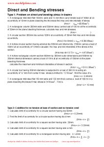
Figure 1: Lloyd Instruments “LS100 Plus” testing machine
3. SPECIMENS AND THREE-POINT BEND TEST PROCEDURES Five HDPE tube specimens with dimensions 4 x 63 x 100 mm have been subjected to three-point bend test on a “LR5K Plus” testing machine produced by Lloyd Instruments, UK (fig. 2). The testing machine presents the following specifications [7]: • force range: 5 kN; • speed accuracy: <0.2%; • travel: 840 mm • load resolution: <0.01% of load cell used; • extension resolution: <0.1 micron; • load cell: XLC-5K-A1; • analysis software: NEXYGEN Plus. The specimens have been subjected to a test speed of 1.5 mm/min and the span has been chosen of 60 mm. Following main features have been determined: stiffness, Young modulus of bending, flexural rigidity, maximum bending stress at maximum load, maximum bending strain at maximum load, extension at maximum load, extension at maximum extension, etc.
279
Figure 2: Lloyd Instruments “LR5K Plus” testing machine
4. RESULTS Tensile and three-point bend results (force-extension and stress-strain distributions) are presented in figs. 3 – 6.
Tensile tests on 4 x 10 x 150 HDPE specimens 900 800 700
Force [N]
600 500 400 300 200 100
Extension [mm]
Serie1
Serie2
Serie3
Serie4
Serie5
Figure 3: Force-extension distributions of five HDPE specimens subjected to tensile tests
280
20,1
19
17,8
16,6
15,3
13,6
12,3
11
9,77
8,59
7,44
6,25
4,99
3,92
3,11
2,42
1,77
1,14
0,52
-100
0,02
0
Tensile tests on 4 x 10 x 150 mm HDPE specimens 25
20
Stress [MPa]
15
10
0,40
0,38
0,36
0,33
0,31
0,27
0,25
0,22
0,20
0,17
0,15
0,13
0,10
0,08
0,06
0,05
0,04
0,02
0,01
0
0,00
5
-5 Strain [-]
Serie1
Serie2
Serie3
Serie4
Serie5
Figure 4: Stress-strain distributions of five HDPE specimens subjected to tensile tests
Three-point bend tests on 63 x 4 mm HDPE tubes
2500
Force [N]
2000 1500 1000 500
63,69
59,74
55,80
51,85
47,90
43,96
40,01
36,08
32,13
28,18
24,24
20,30
16,36
12,41
8,46
4,53
0,58
0
Extension [mm] Serie1
Serie2
Serie3
Serie4
Serie5
Figure 5: Force-extension distributions of five 63 x 4 mm HDPE tubes subjected to three-point bend tests
281
Three-point bend tests on 63 x 4 mm HDPE tubes
Maximum bending stress [MPa]
4,5 4 3,5 3 2,5 2 1,5 1 0,5 3,76
3,53
3,30
3,06
2,83
2,60
2,36
2,13
1,90
1,66
1,43
1,20
0,97
0,73
0,50
0,27
0,03
0
Maximum bending strain [-] Serie1
Serie2
Serie3
Serie4
Serie5
Figure 6: Stress-strain distributions of five 63 x 4 mm HDPE tubes subjected to three-point bend tests
5. CONCLUSIONS From the tensile tests following conclusions can be drawn: • the force range is between 680 N (specimen 4) and 790 N (specimen 2); • extensions are up to 21 mm; • stresses are between 18 MPa (specimen 3) and 23 MPa (specimen 5); • strains are up to 0.41. From the three-point bend tests following conclusions can be pointed out: • the force range is between 1700 N (specimen 3) and 2000 N (specimen 1); • extensions are up to 110 mm; • stresses are between 3.2 MPa (specimen 1) and 3.8 MPa (specimen 4); • strains are up to 6.5. The results show that ths high density polyethylene represent a suitable material to manufacture HDPE tubes for water supply networks applications.
REFERENCES [1] Mohanty, S., Nayak, S.: Mechanical and Rheological Characterization of Treated Jute-HDPE Composites with a Different Morphology, Journal of Reinforced Plastics and Composites, Vol. 25, No. 13, 1419-1439 (2006). [2] Paesano, A., Cohee, D., Palmese, G.R.: Carbon-Fiber Reinforced Thermoplastic Materials for Rigidizable Space Systems, Journal of Thermoplastic Composite Materials, Vol. 16, No. 2, 139-170 (2003). [3] Liang, J.Z., Yang, Q.Q.: Mechanical Properties of Carbon Black-Filled High-Density Polyethylene Antistatic Composites, Journal of Reinforced Plastics and Composites, Vol. 28, No. 3, 295-304 (2009). [4] Fei, Y., Jianjun, Z., Yanghui, Z., Peide, L., Lin, J.Z., Chow, T.T.: Preliminary Real-scale Experimental Studies on Cable Fires in Plenum, Journal of Fire Sciences, Vol. 21, No. 6, 465-484 (2003). [5] Ambroziak, M., Zdunek, K., Wronikowski, M.: Some Technological Aspects of Optical Fibre Cable Production, Journal of Wide Bandgap Materials, Vol. 8, No. 3-4, 219-232 (2001). [6] Lloyd Instruments. LS100 Plus User Manual. [7] Lloyd Instruments. LR5K Plus User Manual.
282