Field of Armor 1/6th SCALE ‘RC Combat’ TIGER 1 Ausf.E INSTRUCTIONS
Items needed for construction: - Well ventilated, clean 4' x 4' working space - 1 can black or clear ABS Glue (available in plumbing section of hardware stores in a blue can) - 1 roll of 1 masking tape (Duct tape or clear packing tape may leave glue residue on the kit plastic) - Sharp utility knife cutting blade - Electric drill with 1/16” & ¼” drill bits - Measuring tape - Pencil - 2 oz. Super Glue gap filling (available at your local hobby store) - Accelerator or Glue Kicker (available at your local hobby store) - Wire cutters or linesman type cutters - Hand Riveter for 1/8” and 3/32” rivets (available at your local Hardware store) - Heat gun or hair dryer - Metal file - Hacksaw - Needle nose pliers - 3/16 inch socket or nut driver - Sandpaper (80 &100 grit)
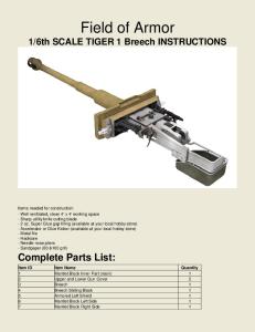
Complete Parts List: Utility Metal Part (Screws, Nails, etc.) Plastic Tubing, and Misc. Plastic Parts Item ID Item Name FOA10001-070M Piano Hinge 1"x 3/4" FOA10001-071M Piano Hinge Screw #3 x 1/2" flat Head self taping FOA10001-073M Drive Gear Axle 1/4"-Dia (21-1/2" Length) FOA10001-074M Inner Axle 1/4"-Dia (20-1/2" Length) FOA10001-075M Idler Axle 1/4"-Dia (18" Length) FOA10001-076M Push Nut FOA10001-077M Small Screws 4-40 x 1/4" Screw (Machine) FOA10001-078M Muffler Cover FOA10001-079M Side Mud Flaps FOA10001-080M 3 1/2" Nails FOA10001-091T 3/8" (OD)-1/4"(OD) Spacer Material 50" Length FOA10001-092T PVC 3/4"-Dia 36" Length – Main Barrel FOA10001-093T PVC 3/4"-Dia Barrel 11-1/3" Length – Turret Counter Weight FOA10001-094T PVC 1-1/2" Dia 5-3/4" Length Sch 80 - Exhaust FOA10001-095T PVC 1-1/2" Dia Barrel 4-1/4" Length – Second Stage Barrel FOA10001-096T PVC 2" Dia Barrel 5" Length – Third Stage Barrel FOA10001-100P Front Gear Wheel FOA10001-101P Idler Wheel FOA10001-102P Road Wheel FOA10001-103P Plastic Track FOA10001-104P Plastic Track Pin FOA10001-111P Grill Front FOA10001-112P Grill Back FOA10001-120P Back Mantlet Piece FOA10001-121P Mantlet Front FOA10001-123P Turret Lift Mounts (These are located with the Back Mantlet) FOA10001-122P Turret Basket FOA10022 Utility Tool Kit FOA10025 Sprue For Hinges
Quantity 4 8 1 8 1 20 36 2 8 12 1 1 2 2 1 1 4 4 32 184 184 2 2 2 1 2 1 1 1
Resin Item ID FOA10001-025R FOA10001-026R FOA10001-027R FOA10001-029R FOA10001-030R FOA10001-031R FOA10001-032R FOA10001-033R FOA10001-034R FOA10001-035R FOA10001-036R FOA10001-037R FOA10001-038R FOA10001-039R FOA10001-040R FOA10001-041R FOA10001-043R FOA10001-044R FOA10001-045R FOA10001-046R FOA10001-047R FOA10001-048R FOA10001-049R FOA10001-050R FOA10001-051R FOA10001-052R FOA10001-053R FOA10001-054R FOA10001-055R FOA10001-056R FOA10001-058R FOA10001-059R FOA10001-060R FOA10001-061R FOA10001-062R FOA10001-063R FOA10001-064R FOA10001-065R FOA10001-066R FOA10001-067R FOA10001-069R FOA10001-070R FOA10001-071R FOA10001-072R FOA10001-073R FOA10001-074R
Item Name Escape Hatch Escape Hatch Hinge Escape Hatch Hinge Cover 2nd Stage Barrel Attachment 3rd Stage Barrel Attachment Ring Loader Vision Port Large Periscope Commander Cupola Commander Hatch Commander Hatch Arm Commander MG Ring Loader Hatch Upper Deck Ventilator Close Defense Weapon Fire Extinguisher Engine Starter Cover Engine Starter Cover Hinge Jack Rest Block Driver & MG Hatch Front Hatch Periscope Ventilator Armor Cap Ball Mount Ball Mount Machine Gun Headlight Bosch Headlight Arm Headlight Connector Driver Vision Port Driver Visor Deflector Engine Starter Attachment Rear Tow Eye Bracket Jack Jack Base Jack Upper Rear Mud Flaps R Rear Mud Flaps L Tow Hitch Exhaust Cover Back Port Engine Starter Port Muzzle Brake Front Tow Eye Brackets R Front Tow Eye Brackets L Ventilation Aperture Armoured Cap Jack Arm Muzzle Inner Ring Muzzle
Quantity 1 1 1 1 1 2 1 1 1 1 1 1 1 1 1 1 2 1 2 2 1 1 1 1 1 1 1 1 1 2 1 1 1 1 1 1 2 2 1 1 1 1 1 1 1 1
ABS Item ID FOA10001-001A FOA10001-002A FOA10001-003A FOA10001-004A FOA10001-005A FOA10001-006A FOA10001-007A FOA10001-008A FOA10001-009A FOA10001-150A FOA10001-010A FOA10001-011A FOA10001-012A FOA10001-013A FOA10001-014A FOA10001-015A FOA10001-016A FOA10001-017A FOA10001-018A FOA10001-019A FOA10001-151A FOA10001-152A FOA10001-153A FOA10001-154A FOA10001-021A FOA10001-022A FOA10001-023A FOA10001-024A FOA10001-025A FOA10001-155A FOA10001-156A FOA10001-157A FOA10001-158A
Item Name Rear Upper Panel Rear Lower Panel Side Panel Left Side Panel Right Base Plate Vertical Support Front Panel Front Lower Panel Front Top Panel Front Eye Thickness Side Panel Right Side Panel Left Front Internal Cross Brace Rear Internal Cross Brace Front Glacis Plate Upper Deck Support Rail Upper Deck Underside Plate Back Panel Extra ABS Panel Material Rear Deck Exhaust Bottom Rear Deck Exhaust Top Turret Ring Engine Hatch Rear Storage Bin Top Rear Turret Roof Front Turret Roof Front Mud Flap Front Mud Flap Connecters Storage Lid Side Turret Protrusion Front Upper Turret Cover Front Lower Turret Cover
Hull Location LOWER HULL LOWER HULL LOWER HULL LOWER HULL LOWER HULL LOWER HULL LOWER HULL LOWER HULL LOWER HULL LOWER HULL UPPER HULL UPPER HULL UPPER HULL UPPER HULL UPPER HULL UPPER HULL UPPER HULL UPPER HULL UPPER HULL UPPER HULL UPPER HULL UPPER HULL UPPER HULL UPPER HULL TURRET TURRET TURRET TURRET TURRET TURRET TURRET TURRET TURRET
Quantity 1 1 1 1 1 2 1 1 1 2 1 1 1 1 1 1 1 2 1 1 1 1 1 1 1 1 1 2 2 2 4 1 1
(***NOTE - The flat black plastic pieces have a smooth side and a rough side. The smooth side is meant to be the exterior surface. When in doubt - SMOOTH SIDE OUT!!! If you want the rough look, turn the parts around.)
Resin
QTY 18 2 16 22 18 54 102 10 18 100 40 18 36 20 156 18 18 3 9 9 34 2 32 2 2 4 32
Graph # 1 2 3 4 5 6 7 8 9 10 11 12 13 14 15 16 17 18 19 20 21 22 23 24 25 26 27
40 18
28 29
Hardware Description 3 ½”L Grooved 3/8” Hex Bolts 3”L 3/8” Hex Bolts 3 ½”L ¼” Hex Bolts 2”L ¼” Hex Bolts 5/16”L ¼” Hex Bolts 1”L 4-40 Pan Head Bolts ½”L 4-40 Pan Head Bolts 4”L ¼” Socket Cap Bolts 2”L 10-32 Socket Cap Bolts 1/8” 3/8” Head Steel Rivets 3/8” Jam Nuts ¼” Heavy Nuts ¼” Normal Nuts ¼” Flat Nuts 4/40 Nuts 10-32 Nylok Nuts ¼” Nylok Nuts ¼” Washers Right Hand Spring, tangential Leg Left Hand Spring, tangential Leg 3/8” ID Sleeve 2 ½”L 3/8”ID Sleeve ¼” ID Sleeve 1 ¾”L Aluminum Hub w/ Set Screws Large Hull Hinge Double Roller Catch ¼” ID 3/8” OD Bushing
Item’s Use Swing Arm to Spring bolt (road wheel & Idler) Idler Wheel bolt Road Wheel bolt Rail attachment to Hull Spring lock on rail half-moon Double Road Wheel Single Road Wheel Sprocket bolts Suspension Arrestor Body Suspension
3/8” ID ½” OD Bushing 1/2” ID Nylon Washer
Rail Between hull and swing arm
Road Wheels Suspension Arrestor
Left side Hull Spring (opposite for Idler Spring) Right side Hull Spring (opposite for Idler Spring) Rail to Swing Arms Idlers Road Wheels Sprockets Front Hull Turret and Front hull snaps Road Wheels
There are no jigs needed to build your Tiger tank. Instead, masking tape will be used to secure all joints. Make sure that you pull the joints together tightly when you secure with masking tape to ensure a strong joint. Super Glue, Modelers Cement and ABS Glue can be sanded easily when cured. If your glue joints aren't as clean as you would like them, let the glue fully cure then sand and fill as necessary. This is an “RC Tank”, which means it will drive in rough environment and will be subject to continuous vibrations. We have provided small “counter-sink” screws at critical locations with hidden metal brackets to reinforce the strength of the tank, and still keep its light weight relative to its size. It will be necessary to counter-sink some of the holes in the ABS, then putty (or add ABS glue), and finally sand to hide these screws. Add screws on the inside of the tank wherever a resin accessory part is added on its hull/turret. Superglue might not be enough to secure the part during RC operation. All laser-cut metal parts provided are MILD STEEL. Clean the steel with Lacquer Thinner (it will remove any oil residual and improve paint and glue retention) and Prime the parts before assembly to avoid rust.
Please visit FOA Forum to benefit from other customer’s experiences in building the FOA RC Tiger I Ausf.E (click on this link)
LOWER HULL ASSEMBLY The lower hull is made of a Laser-cut metal INNER SHELL, and 3/16” ABS OUTER HULL. Shown below are the parts required to build the lower hull assembly.
Locate the metal INNER SHELL. NOTE that the pre-drilled holes of the motor’s ESC are toward the right side of the tank. Fold-up the two sides as shown in below picture (the sides might already be folded during shipping. Just “unfold them to the UP position (folding and unfolding metal parts will ultimately separate the parts. If this happens, do not worry because the suspension rail will also connect the parts). Fold up the front hull part. Do the same on the back hull. DO NOT use rivets yet.
Locate the lower front hull glacis (2 parts) and position in appropriate slots. At that time, add two rivets on both sides between the metal tab and the side hull.
Locate the back hull ABS part, and position in appropriate slots. Add one rivet on both sides between metal tab and the side hull. Install the Velcro battery straps BEFORE the bottom ABS hull. It will hide the straps from the bottom of the vehicle
Install: 1. 2. 3. 4.
ABS bottom hull Two 12V Battery Base Mounting Brackets (red in photo below) Fuse Block, with common ground on the right side of vehicle Four ESC (Electronic Speed Controllers) – You might have just two high amperage ESC if using them for motorization only. Smaller ESC could be used for Turret Rotation and Gun Elevation.
The above photo shows the lower hull floor Locate the rear hook brackets, and glue/screw on the back hull, against the metal hook bracket of the same shape. Careful to avoid the bolt heads on the inside of the hull, because the upper rear hull will slide between the hooks.
Locate the front hook brackets and the inside bracket, and glue/screw on the front hull, against the metal hook bracket of the same shape. Note that the screw holes were counter-sink on the outside hull, but are showing on the inner hull. In the photos below, this addition was done after installation of the motorization system.
UPPER HULL ASSEMBLY When completed, the upper hull assembly is meant to remain separate from the lower main hull so that it can easily be accessed for RC maintenance.
Locate the two side hull, front hull, and two inner ABS braces. Note that those braces have slots which are oriented toward the bottom, as they will slide into the lower hull’s side walls. Most of these ABS parts have slotted edges which will match into the other ABS parts slotted edges. The front ABS brace is not as tall as the back brace, and has a cut in the upper middle section. Both braces will fit into corresponding cuts on either side of the side-hull walls. NOTE: the long slotted part# is glued on the inside of the front full wall. The upper deck will fit into the slot. Make sure the side-hull walls have the fender’s holes on the bottom
Slide front and rear cross braces into the slots at the front and rear of the lower main hull. Take the side panels and dry fit them to front and rear internal cross braces. Make sure that the side panels are oriented so that the smooth side is out and the 16 small holes are on the bottom.
After you have dry fitted the panels, remove them, apply ABS Glue and assemble back together. (The sides should stay in place on the inner braces. If they don't, secure them with masking tape.) (NOTE: When applying ABS Glue to a joint, place glue around hole and on lower parts of tab.)
Dry fit back panel to the rear side of the side panels to check the fit. Apply ABS Glue to the joint between the back panel and side panels. When applying masking tape to secure flat laser pieces, apply first to the overlapping side of the tab and then pull to close any gaps. Install the upper deck, sliding the front deck into the long slot and matching all slotted edges as indicated below Remove the upper deck and apply glue to all of the joints where the upper deck fits onto the upper hull assembly. Since there are a lot of joints that need glue, do this as quickly as possible. Remember, any excess ABS Glue can be sanded smooth after it has fully cured (overnight). Slide the deck back into place. Starting at the back, secure deck with masking tape alternating sides every 1 1/2 inches as you work toward the front. Work your way around the deck uniformly on both sides until the entire deck has been taped down. After the upper deck is fully secured with tape, place the upper hull assembly upside down so you have access to each joint from the INSIDE.
Use ABS glue to cements all the panels together
Find the six metal hull brackets. They will be installed on the corners of the upper hull, to add strength during RC operation.
Position the brackets in each corner, except on the front hull.
The final pieces that need to be applied to the upper hull assembly are the underside plates. Dry fit and glue the underside plates to the bottom of the side plates, the front glacis plate and the back plate. Secure joints every 1 ½” with masking tape. (NOTE: You may find that one of the underside panels, even when placed on correctly, has the rough side out. This should not affect the look of your Tiger 1 because it cannot be seen when the upper hull assembly is placed onto the lower hull.)
EXHAUST SYSTEM ASSEMBLY The upgraded exhaust system can be made functional. Locate the two muffler connectors, and glue them on the back hull. The large ABS hole should be ½”, and connect directly into the muffler connectors. Drill a ½” hole into the 1 ¼” PVC pipe, 2” from the end.
Add two counter-sink (on the inside) screws through the ABS, resin muffler connector, and to the PVC pipe. Add nuts on the inside of the PVC pipe.
Glue the muffler end caps, fully closed on the bottom, and with a center hole and six grooves on the top. Use counter-sink (on the inside of the hull) screws to mount the two armored muffler covers. Nuts are on the outside.
The six nails can now slide into the upper muffler ABS ring, and be super-glued to the PVC pipe after fitting through the six grooves on the upper resin cap.
Half-rounded large gauge wires are provided to add detail on the lower and upper ends of the muffler covers. Sand the metal and the flat side of the wire before super-gluing. The Position of the resin accessory parts of the back hull is detailed at the end of this manual.
Fold the inner rear fender, to get the four holes aligned. Do not counter-sink the holes for the screws since the rear sliding plate does not go over the fender’s ABS inner wall.
UNDER-CARRIAGE ASSEMBLY 32 ROAD WHEEL SET Road Wheel Construction NOTE. Before commencing the metal plates were painted with a rust preventing paint. Single wheel assembly – 16 wheels Step1. Use the sixteen wheel plates with 6 outside holes and 3 inside holes. Drilled out all the metal plate small holes to give proper clearance for the screws.
Step 2. Next use a centre drill to accurately mark the centre of two opposite nuts on the plastic wheel. I then drilled these through with a 3mm drill.
Then using a modified drill or a sprue cutter, removed the drilled molded nuts.
Step 3. Next secure the metal disc to the wheel ensuring they are concentric with each other using two 4-40 x ½ in. screws and nuts. Then drill the remaining holes with a 3mm drill and spotted the three pop rivet holes. Then removed the molded nuts, as before in step 2, on the drilled holes.
Step 4. Then marked the edge of the wheel and disc to ensure the same alignment when re-assembled and separate the two. Next counter-bore the three rivet holes using a 5mm drill, NOT going right through the wheel, to allow the pop rivets to expand behind the disc properly when fitted later.
Next re-assembled the disc and wheel making sure the alignment marks lined up and secured the short screws and nuts using BLUE loctite on the threads.
Step 5. Using the metal as a template, center a ½ inch drill in the center hole and clamp the wheel to the drill press bed before drilling. *Note it is advisable to back off the cutting edge of the drill to prevent it grabbing into the plastic when drilling.
Finally the 3/8ID x ½ OD bushing was inserted into the wheel and the small plate pop riveted to secure it. Take up the tension of the rivets gradually and evenly to keep the plate level before finally snapping off the rivets.
Double wheel assembly – 8 double wheels Step 6. Use the eight wheel plates with 6 outside holes only. After aligning, drilling and removing the molded nuts on two wheels, mount a six hole plate to one wheel using three 440 x 1in. screws and nuts.
Then join the two plates together leaving the nuts between the two wheels and drilled the centre to 1/2in. Separating the wheels I inserted the bushings and joined the wheels together with the remaining screws and nuts. The three extra nuts between the wheels ensure the plate is firmly attached to the wheel not just relying on the bushes to trap it tightly. OPTION: to avoid the space between the wheels, do not use the extra nuts between the wheels, as the outside nut will push the two wheels together.
When all wheel sets were rotated on an axle sleeve they ran perfectly concentrically with the axle without any side wobble.
IDLER WHEEL Four Idler wheels are provided in the kit. They were pre-filled with resin or rubber to fill any void that would weaken them as they are pressed together. The same force exerted by the sprockets is received by the Idler wheel, tensioned by the spring idler arm. First, cut off the top of ONE idler wheel as indicated below. Drill same ½” hole in the wheel for the bushing
Photo below with bushing
Take the metal idler ring to center with bushing to drill the three holes as indicated below
Follow the SAME procedure for the ‘uncut’ wheel. Trim around the edges to allow for the nut. This side will be hidden toward the hull of the tank
The nut will show as below.
The photo below shows the side SHOWING, which will be covered by a metal idler cover
The photo below shows the side NOT SHOWING, with permanent red locktite.
SUSPENSION INSTALLATION Follow the instructions provided on this link to install the suspension arms https://drive.google.com/file/d/0B93YuQpNXDGITUE1b2loeVRfMzg/edit The rail is a 16-gauge metal part that requires folding. There are several ways to fold this part. One would involve a 1” square wood piece that would fit inside the rail. Below is another way to fold this hard metal
Use Plyers to hold each face and fold them, using a vise when required
Note the end tabs which should be inserted INSIDE the rail. It will avoid the collapse of the rail when tied against the hull with a bolt.
Fold the tabs on the OUSIDE of the rail and use 1/8” rivets to secure them
Now, let’s install the swing arms
Fold the outer plate around the two 12-gauge inner plates, using a long-nose plier. Make sure to fold the outer plate considering that the “swing arm stopper” will be fitting on the top, with all arms orienting backward NOTE: The German Tigers and Panthers had the right-side swing arms oriented toward the FRONT, because of their torsion bar suspension system. This RC Tiger will have BETTER obstacle capabilities if both sides have the swing arms orienting toward the back. This design is based on scaled RC capability rather than historical accuracy – because it is HIDDEN.
Remember that the “arm stopper” on one swing arm is INSIDE the arm toward the hull, and oriented UP Slide the 3/8” grooved bolt
Insert the 3/8” ID sleeve into the 3/8” grooved bolt. The POSITION of the groove can be changed by moving the HEX bolt head around the swing arm outer plate HEX cut. IT IS VERY IMPORTANT: this is the coarse adjustment of each arm of the suspension system
Insert the nylon spacer and the bushing on the sleeve and slide into the hull.
Another bushing will fit into the other side of the rail
Insert the spring. Make sure that the “tangential leg” of the spring is toward the back of the hull. This is a COMPRESSION spring. As the spring arm goes up, the spring should tension against the
TRACK LINK INSTALLATION
With the lower hull turned over, slide it to the edge of your table so that one set of wheels sticks out. Take a track set and notice that on one side there are slots or tabs that stick out somewhat beyond the track itself. The tracks should be oriented so that the tabs face the inside of the tank. Place the tracks onto the road wheels, over the idler wheel and around the drive gear. Check to make sure that the teeth on the drive gear are aligned into their holes and slots on the track. Balance the tracks so that you have a somewhat even amount of track on either side hanging down. (The back idle wheel sits in the middle of the guide horns.) Connect the tracks together with the pin and repeat for other side. Turn lower hull over and push the track back and forth, checking for alignment. Once you are satisfied with the alignment, take the tracks off the tank.
FRONT HULL PLATE Locate the long thin ABS piece and front hull plate. Cut 5 pieces that are each ½” long. Use one of the pieces as a spacer to glue the other 4 pieces to inner front lower hull. Let the 4 pieces dry for about 5 minutes. These will become the support for the front main hull plate.
Dry fit the front hull plate. (You may need to round the corners of the front hull plate for a better fit to the lower hull body.) Glue the hull plate and secure with masking tape. Be careful not to push down on front plate and break loose the tabs. The front plate should stay flush with the undercarriage.
Apply a generous second coat of ABS Glue from the inside to all the joints. This is a good time to spray primer on the outside of the main hull wheels and under-carriage if you have not already done so. Let cure overnight. TURRET ASSEMBLY Cupola Take the cupola hatch pin and make sure that it fits easily into the cupola hatch pinhole. Drill out hole as necessary. Clean and sand if necessary. Glue the hatch to hatch pin. Dry fit and glue machine gun rail to cupola.
Turret ammunition hatch Locate ammunition hatch hinge, receiver and hatch. Orient the door so that the bevels are on the left and right. Make a mark at the bottom of the door. You can also place the hinge on the door and trace the hinge. Remove door and using Super Glue, attach the hinge with receiver to ammunition hatch. Barrel Assembly Orient the mantlet as shown in below picture. The MG hole should be higher than the left scope hole. Some Tigers had two scope holes.
Glue the resin parts at the end of the PVC pipe, on both different diameters.
Take the cone shaped barrel ring and carefully sand it internally until the cone fits over the barrel. Be patient and sand and dry fit the cone until you can slide it down to the 14 1/2 inch line. Make sure that the tapered end of the cone faces the muzzle break. Attach to barrel with Super Glue. Take the second stage barrel and fit flush around all sides of the cone. Attach with Super Glue. Take the third stage barrel attachment ring and slide onto barrel. Make sure that the groove ring faces the muzzle break and slides into the second stage barrel. Glue to second stage barrel and long barrel. Take the third stage barrel and dry fit, then glue to attachment ring. Slide on front mantlet and dry fit but DO NOT glue just yet.
Remove of the LIP under the turret
Building the Stowage Bin
Installation of the TTRS Turret Rotation System
Insert the metal back mantlet between the turret sides (old type Turret with attached Stowage on this picture)
TURRET ROOF (taken from the Static Kit instructions, some parts may differ) Take the rear turret roof, upper loaders hatch and 2 hinges. Sand hinges, if needed, to bring hinges and hatch flush. Placing the hinge tab on the raised sections of the loaders hatch, glue hinge onto loaders hatch. Do not glue to turret roof yet. Take the small ABS strip and cut 16 pieces of ½” long strips. (Depress with a cutting knife and then snap off.) Put ABS Glue on ½ of the inner turret wall at the top. Place 8 of the ½” tabs 3/16” down from the top of the turret. Use a separate ½” piece to be your 3/16” guide. Repeat for the other half.
Take the rear storage bin top and glue it into place. Tighten all joints with masking tape. Using the center of the storage bin as an anchor point to work from, tighten from the back first and move to the sides checking that all joints
are flush and closed.
Dry fit rear turret roof and front turret roof. Flush the front turret roof with the front of the turret. Put in the mantlet back.
Mark on the turret where the front and rear turret roof plates meet. This will allow you to remove the roof and replace it with glue while maintaining the alignment. Apply ABS Glue and put in the rear turret roof. Starting at the loaders hatch area, affix with masking tape making sure to close all gaps. Work your way around until you have secured the entire rear turret roof.
Make sure your mantlet is facing forward. Dry fit and glue the front turret roof. Do not apply glue to the narrow front edge. Starting in the middle, tape the front turret hatch to the rear roof. Take a couple of long pieces of tape and pull the turret sides together firmly to remove all gaps.
Turn turret over and generously coat all seams with ABS Glue. Turn back over and check to make sure that all joints are still flush to the top. Adjust and secure with more tape as necessary. Dry fit and glue lifting lugs to turret sides. Rotate to make parallel (narrow side to the rear). Glue from the outside with Super Glue. Rotate the mantlet while glue is curing to ensure the mantlet moves freely. Use Accelerator to set Super Glue so it doesn't drip into mantlet. Repeat on the other side. Because these were welded on to the turret in real life excess glue around the edge is okay. Close all gaps with Super Glue and Accelerator.
Dry fit horizontal bars to the underside and top of mantlet.
Let dry overnight. Attach the upper loaders hatch. First, draw a centerline going both ways on the loaders hatch hole on the upper rear turret roof. Find the center on the loaders hatch in both directions as well and mark. Line up centerlines and trace loaders hatch. Place Super Glue within the traced outline. Test door to see that it opens. Place the loaders vision port right on the ridge line centered between the 2 hinges of the loaders hatch. Trace and use Super Glue to attach. Repeat on left side except move side vision port back approximately 1”. Place the close defense weapon port with the inside edge of the loaders hatch and 1 ½” back from the hatch. Make
sure that the oval hole in the close defense weapon port is facing forward.
Place the ammunition hatch on and dry fit, then glue with Super Glue. Make sure the hinge sits at the bottom. Secure with masking tape while you work.
Attach hinges to storage bin hatches. Make sure hatches have the smooth side up and fit flush around the storage bin. Place hinges ½” in from the sides of the hatches and glue with ABS Glue or Modelers Cement. Trace and glue to roof. Place cupola to the joint of the turret roof and turret side. Cupola pinhole needs to be parallel to an imaginary line with the roof joint. Trace and mark a line where the hatch pin is. Place Super Glue on the turret roof and replace cupola. Place the upper ventilator ½” back from the roof joint and ½” in from the cupola. Take the 4 small ABS tabs and align them above and below the lifting hooks, pointing down at the lifting hooks and 1/8” back from the corner. The second one fits on the bottom below the lifting hook. Place on an imaginary line from the upper piece ¼” from the bottom front corner of the turret. Secure with ABS Glue or Modelers Cement. Repeat on the other side.
Secure all hatches with masking tape and turn the turret over. Place front mantlet onto back mantlet making sure that the raised horizontal ridge on the front mantlet is on the right side of the turret as you look at it from the front. Use ABS Glue to attach.
Slide barrel into place. Rotate barrel so that the openings in the muzzle-break face outward. Apply Super Glue where the stage three barrel and front mantlet meet. Also, make sure the mark you made for the counterweights inside the turret is visible. Insert the counterweights on either side and tape them into place.
UPPER HULL DETAIL ASSEMBLY Take the front mud flap brackets and insert the hinges into the slots. Flush the hinges with the bottom of the bracket. Place a spacer under the mud flap so that it is the same height as the mud flap bracket. Flush the mud flap and the bracket along the straight side. Use Modelers Cement and glue the hinge tabs to the mud flap. Let sit overnight.
Assemble the front deck hatches. Take the U-shaped piece of the hinge and clean the flash or excess plastic. Be careful not to trim off the nipples located inside the U shaped piece. Take the V-shaped arm and with a metal file put a slight angle on both sides of the inside of the swivel arms at the insertion point. This should take about 6 to 7 strokes with the file. Be careful not to file deep enough to interfere with the holes. The taper will allow the U-shaped piece to snap onto the V arm and remain snug. Push the U-shaped piece onto the V-arm from the tapered end using the taper to assist in snapping the two pieces together. Glue the V-hinge as close to the rim on the inner ring as possible and center it along the flat edge side of the hatch. Take the teardrop shaped piece and hold it with the flat side facing up. Take the file and with 6 to 7 strokes, taper both sides in the same manner as the V-arm. Take the U-shaped bracket and, from the tapered side, snap the 2 pieces together.
Find the hook hinge that you will use for the rear engine grills. Take the hook hinge and U-receiver and simply snap it together. There is no need to put a taper onto the hook arm. The engine back plate needs to have 2 hinges inserted into it so that the engine hatch cover can open and close. Hinge Prep Sand hinge top and the area near the pins until it is round. Engine Hatch Cover (NOTE: Measure the engine hatch and find the narrower dimension. Draw a line from side to side ½” from the edge. On the opposite end, mark a line 1” from the edge. Following that, make a line down the center of the hatch. Then make a line on the side of the carburetor air intake. Place the line on the intake at the intersection of the 1” line and mid line. Make sure that the intake is spaced evenly on both sides at approximately 2”. Hold down the carburetor air intake and draw a line around it. Lift up the air intake and apply Super Glue to the underside. Replace the air intake back on the hatch inside the circle that you drew. Take the small frame of the air cleaner intake and place a mark in the center. Dry fit it on the ½” line and the centerline on the engine plate. Place ABS Glue to the rough side of the 2 parts and replace onto the engine plate. Super Glue the back engine plate hinge tabs onto engine plate. Be sure to leave enough space between the back plate and the engine plate to allow the hinge to work. However, the hinges are not meant to be used for rugged use.
Jack Lay the jack body down on the flat sanded end. It is important that you glue the pieces flush with the flat side of the jack body so that the jack can glue to the back of the tank. Take the waffle looking bottom plate and center it to the jack body and glue them together with Super Glue.
Machine Gun Barrel with Ball Mount Dry fit the machine gun barrel into the ball mount. The barrel should measure 2” from the ball mount to the front of the barrel. If you have more than 2”, cut off the excess. Orient the ball mount so that the small hole sits on the right. Super Glue the barrel into place making sure that the seam is facing downward.
Grill Trim and dry fit the grill front and back pieces. If the hinge feels stiff, trim the hinge area a little more and work hinge back and forth to loosen it up. Locate the long hinges and hook. With the long hinge facing forward, glue hook to grill using Modelers Cement.
ATTACHING PARTS TO THE UPPER HULL Resin parts: Hinges and tow shackles, fire extinguisher, tension covers, engine starter cover, starter holder, rear tow eyes, upper deck ventilator, ball mount, ball mount machine gun, wooden block, headlight, driver's vision block, front hatches, periscopes, mufflers, muffler covers, jack, back mud flap, grill, side mud flaps, and small screws
Front Hatches Take the front hatches, put them in the hatch holes and rotate them so that the flat of the hatches are facing outwards and are parallel to the sides. Tape in place to the upper deck assembly.
Turn the upper deck assembly over. Using ABS Glue or Super Glue, attach the other side of the V-hinge to the upper deck assembly. (If you use ABS Glue you should let the hinge dry for 10 minutes after which you should reinforce the joint with another coat of ABS Glue.) Repeat for the other side
Take the turret bullet splash guard and dry fit the tabs in the holes bending it around as you go. Remove and glue with ABS Glue.
Turn the upper deck assembly over and using Super Glue, attach periscope to hatch as shown. Measure 2 ¾” from the center mark from the flat area to the outer rim and put a mark. Place the periscope so that the end of it is parallel with the outer rim. Refer to outer rim. Using a measuring tape and pencil, mark 3 lines from the right of the tank when facing the tank. One at 7 ¼”, one at 10 ½”, and one at 14“. Dry fit the driver's vision block. Find the middle of the vision block and mark it. (Sand the back of the vision flush if needed. Also, make sure that any excess ABS is sanded off of the front glacis plate as well). Flush the bottom of the vision block with the bottom of the glacis plate and align the center mark on the vision block with the 7 ¼” line. (NOTE: If you don't intend on ever removing the upper deck assembly, you may want to wait on this part and glue it together with the lower hull.) Dry fit the headlight bracket at the 10 ½” mark on the front glacis plate. Fit headlight onto headlight bracket, position and glue. Holding the ball mount facing you (the small hole is to your right) find the center of the outer ring and align this mark on the 14 ½” line. Attach with Super Glue.
Dry fit the wooden block to the upper deck assembly. Make sure that you locate the narrow side of the wooden block ¾” from the back of the glacis plate and 11 5/8” from the right edge of the upper deck assembly when looking at it from the front. Glue the ventilator onto the upper deck assembly approximately ¼” from the back of the glacis plate and 9 3/8” from the right edge of the upper deck assembly to the side of the ventilator. Place a tow shackle at an angle approximately 1 ¾” from the back of the glacis plate and 6 ¾” from the right side of the upper deck assembly. You can choose to glue the shackle on or drill holes for wire brackets that allow you to remove the shackle. Apply ABS Glue or Modelers Cement to the flat bottom of the shackle and attach to upper deck assembly, if not using the removable option. Making the Shackle Removable Take the copper wire that holds the wheels together during shipping and cut off two 1 ¼” sections. Make a 90-degree bend ¼” from each end (It will now serve as a staple). Slide the staple over the shackle at one end and mark the spot where the staples land on the upper deck assembly. Remove the shackle and drill. Repeat on the opposite side of the shackle. Rotate the upper deck assembly 180 degrees so that you are now looking at the rear of the assembly. (Let the longer back plate hang over the table.) Take the grill and make sure to orient it so that the hook on the grill faces outwards. This should put the smaller of the 2 grill plates facing the rear. Dry fit the grill on the upper deck assembly along the seams of the deck side and back plates (3/16” from the back and side edges). Remove the small rear grill plate and place it on the upper deck assembly and trace it as an outline for applying ABS Glue. Remove the small rear grill plate and apply ABS Glue within the outline and position the grill assembly and let dry. Or, if you're using Modelers Cement, simply place the grill on the upper deck assembly and apply the glue to the edges of the small rear grill plate. After a couple of minutes, raise the front grill plate and finish applying Modelers Cement to the rest of the small rear grill plate. Rear End Detail Dry fit the engine hatch cover and engine back plate to the upper deck assembly. Line up engine back plate with the rear of the grills and position evenly between the 2 grills. Using Super Glue, attach the back engine plate to upper deck assembly. Glue engine back plate ONLY if you want to open and close the engine cover. Facing the rear of the upper deck assembly, raise the grill and, using the grill hook, lock the grill in the upward position. Dry fit the fire extinguisher at an angle so as to not interfere with the hook. The top of the fire extinguisher should align with the rib at the end of the first row of arched cutouts. Attach the fire extinguisher using Super Glue.
Lift the upper deck assembly up and place the back plate onto the table. Dry fit the jack in place on the right side of the back plate above the right rear mud flap 2 ¼” down from the top. Flush the jack to the right side and glue with Super Glue. With the holes facing downward and to the left, place the starter attachment to the rear flush with the top seam (approximately 3/16”) and 10 ½” from either side. This will place the starter attachment in the center of the rear plate. Use Super Glue to attach. Make a line at 6 3/8” across the bottom of the back plate. Make another line at ¾” high. Place starter cover so that it sits on the center line and the bottom sits on the ¾” line. Use Super Glue. To attach the track tension covers, make a line ½” from the bottom and ½” in from the side. Position the cover vertically and place it between your 2 lines. Attach with Super Glue. Repeat on opposite side. Position the rear tow hooks with the tow eyelet facing up. Position the tow hook on the edge of the lower back plate flush with the bottom. Attach with Super Glue. Draw a line 1” from the top of the back plate and 4 ¼” in from the left side. Glue or attach with staples as with the tow shackle attached to the upper deck.
Rotate the upper deck assembly 90 degrees on the table. Locate the side mud flaps and small bolt pack. Take the 3/16-inch nut driver and starting at the front, apply sufficient inward pressure and screw the side mud flaps on. Snug screws up but be careful not to over tighten. Some of the holes may have ABS Glue in them from prior assembly. Clean out hole with 1/16 inch copper wire if necessary. If you desire, from inside the tank, apply a coat of ABS Glue to the screw tips to lock them in place. After the ABS Glue is fully dried, bend the side mud flaps up or down to match each other.
LOWER HULL FINAL ASSEMBLY Set aside the upper deck assembly and retrieve the lower hull section. Remove the masking tape from the front of the hull section. Take the upper deck assembly and, starting with the back, set it onto the lower hull section. Take the front mud flap sub-assembly and place it under the edge of the front glacis plate. Adjust the mud flap bracket so that the ridge along the top lines up with the bottom of the front glacis plate. Adjust the mud flap to match the angle of the lower hull. Since the hinges are not glued to the mud flap bracket, they will move to align the mud flap. When
properly adjusted, carefully turn the mud flap assembly over and Super Glue the back of the hinges to secure. Allow to dry and then turn over and reinforce by gluing the hinges from the top. Be careful not to glue the hinge together. Apply Super Glue generously to the area behind the ridge line and replace the mud flap bracket back onto the tank. Make sure that the mud flap is flush with the front of the tank before applying accelerator. Repeat on the opposite side. Allow to dry.
Place side mud flaps on the upper deck assembly and secure with small screws.
Dry fit the tow hitch to the back plate or the upper deck assembly. Place the hitch in the middle and at the bottom of the back plate.
Field of Armor UTILITY TOOLS KIT INSTRUCTION NOTE: some of the above parts are for the “Static” Tiger I kit. Some variations might occur for the “RC” version of the kit. FOA regularly upgrades resin parts, and some upgraded parts may differ from the above pictures Items needed: - ABS Glue or Modeler Super Glue - Trimmers (Plastic Clippers, knife) - 3/8” Drill Bit (only if installing Utility Tool Set on FOA Tiger 1 Tank)
IMPORTANT: Do not trim the nipples located under the utility tool mounts - they are used for mounting to the Tiger 1.
Also, do not clip off the nipples on the ½ Bar Sleeve or Tow Loop.
Tow Loops: Remove the ½ Bar Sleeves and the Tow Loops
. Apply ABS or Modelers Super Glue on each Tow Loop. Press ½ Bar Sleeve and Tow Loop together. Tow Loop Application for FOA Tiger 1 Tanks: Drill mounting holes on all Tow Eye Brackets to 3/8” to fit the Tow Loop Bar. Mount Tow Loops in all Tow Eye Brackets. Glue Tow Loop Bar to Tow Loop.
Utility Tool Set Illustrations: Tow Loop Mount
Shovel with Mount and Small Strap
Axe with Mount and Large Strap
Sledge Hammer with Large Strap
Pry bar with Mount and Large Strap
Many other accessories are available at Field of Armor Tanks to make your Tiger I Ausf.E Late more accurate. We recommend these accessories below: 1. 2. 3. 4. 5. 6. 7. 8. 9. 10.
FOA10003 Extra Link Set for Turret and Hull FOA10001-400R KwK36 Resin Gun Assembly FOA10001-BREECH Tiger I Breech FOA-ACC028 Late Version Night Tail Light FOA-ACC031 TFZ.9b Double Gun Optics (early to late Tigers) FOA-ACC032 TFZ.9c Single Gun Optics (late Tigers) 6Si-TT03B-K Tank Tow Rope, Alum C/Rod Ends 6SI-TT12B-K Track Tow Rope 6SI-TT08-K Spare Track Clamps Set 6SI-TT11-K MG Mount and Cupola Ring th
There are over 50 accessories from 6 Scale Icons that can replace shovels, axe, muzzle brake and many other accessories on this Tiger I late. Please check the website for the complete list of available kits (click here)