APPLIED PHYSICS LETTERS 90, 243101 共2007兲
Near-field laser parallel nanofabrication of arbitrary-shaped patterns W. Guo Laser Processing Research Centre, School of Mechanical, Aerospace and Civil Engineering, and Corrosion and Protection Centre, School of Materials, University of Manchester, Manchester M60 1QD, United Kingdom
Z. B. Wang,a兲 L. Li, and D. J. Whitehead Laser Processing Research Centre, School of Mechanical, Aerospace and Civil Engineering, University of Manchester, Sackville Street, Manchester M60 1QD, United Kingdom
B. S. Luk’yanchuk Data Storage Institute, DSI Building, 5 Engineering Drive 1, Singapore 117608, Singapore
Z. Liu Corrosion and Protection Centre, School of Materials, University of Manchester, The Mill, Manchester M60 1QD, United Kingdom
共Received 30 March 2007; accepted 16 May 2007; published online 11 June 2007兲 The authors present a simple and efficient technique for laser writing of arbitrary nanopatterns across a large surface area without using projection masks. It is based on the unique near-field focusing effect of a self-assembled particle array on the surface interacting with an angular incident laser beam. The spot resolution can be down to 80 nm. More than 6 ⫻ 106 nanolines and c-shaped uniform patterns were fabricated simultaneously over an area of 5 ⫻ 5 mm2 by a few laser shots. © 2007 American Institute of Physics. 关DOI: 10.1063/1.2748035兴 Laser-induced surface nanopatterning has become increasingly important due to the rapid development of nanoelectronics, nanophotonic, and biomedical devices.1 Due to the optical diffraction limit, light cannot be confined to a lateral dimension smaller than roughly one-half of wavelength.2 In order to overcome this barrier, near-field optics has attracted much attention in recent years, where evanescence wave becomes significant. So far, several near-field patterning techniques exist: near-field scanning optical microscope 共NSOM兲 patterning,3–5 laser-assisted atomic force microscopy/scanning tunneling microscopy 共AFM/STM兲-tip patterning,6–8 contacting particle-lens array 共CPLA兲 patterning,9–13 and plasmonic lithography 共PL兲.14,15 As nearfield techniques, their working distances are in the submicron scale, typically from zero 共contacting mode兲 to several hundreds of nanometers. In NSOM and AFM/STM systems, sophisticated hardware systems were used to control the nearfield distance. In addition the throughput is too low to be used in an industrial environment, as they are serial writing techniques. In CPLA systems, the particle lens is in contact with the surface while in PL system the near-field distance is controlled by spin coating of a transparent spacer layer.15 The CPLA technique employs a regular two-dimensional array of small particles as lens array, which converts a laser beam into a multiplicity of enhanced optical spots in parallel at focus. Unlike fabrication of conventional microlens arrays by complicated processes such as photolithography and resist reflow, the particle-lens array can be easily prepared by a self-assembly process.9,16 The existing CPLA technique is, however, a single-angle processing technique, in which the laser beam is incident perpendicularly to the surface and most of the particles are removed after a single shot.17 The disappearance of the particles makes it impossible to fabria兲
Author to whom correspondence should be addressed; electronic mail:
[email protected]
cate complex array patterns other than a hole/cone array. To enable the fabrication of different user-defined nanostructures such as nanolines, we report in this letter a step change of the existing CPLA technique by using an angular scanning laser beam scanning through the particle-lens array on the surface, and demonstrated laser parallel writing of different profiled nanofeatures simultaneously in a large surface area. In the experiments reported here, a KrF excimer laser 共GSI-Lumonic IPEX848兲 was used as the light source 共 = 248 nm, = 15 ns, and repetition rate of 1 Hz; nonpolarized兲. The sample was a 20-nm-thick eutectic Sb70Te30 film coated on a polycarbonate substrate. Monodispersed 1.0 m spherical silica 共SiO2, Duke Scientific兲 particles were diluted with de-ionized water and applied to the film surface. After the water evaporates, a hexagonally closed-packed monolayer was formed on the surface due to the self-assembly process. The sample was then processed and characterized by field-emission environmental scanning electron microscopy 共SEM; Philips XL32兲 and AFM 共Vecco CP2兲. Figure 1共a兲 shows a schematic diagram of the basic con-
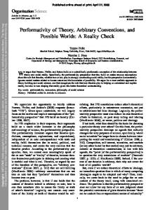
FIG. 1. 共Color online兲 Schematic diagram of 共a兲 the experimental configuration for direct laser writing of nanoline array on substrate surface, and 共b兲 SEM image of two hexagonal nanodent arrays ablated by a single KrF laser pulse at an incident angles of 0°, with fluence of 6.5 mJ/ cm2, and 30°, with fluence of 1.0 mJ/ cm2, respectively.
0003-6951/2007/90共24兲/243101/3/$23.00 90, 243101-1 © 2007 American Institute of Physics Downloaded 12 Jun 2007 to 130.88.106.15. Redistribution subject to AIP license or copyright, see http://apl.aip.org/apl/copyright.jsp
243101-2
Appl. Phys. Lett. 90, 243101 共2007兲
Guo et al.
cept for laser writing of an array of nanolines on a surface. The laser beam was scanned in the xz plane about the y axis from a large angle ␣1 to a smaller angle ␣2 共␣1 ⬎ ␣2 ⬎ 0 ° 兲. It was found that at low-to-medium laser fluences 共typically ⬍10.0 mJ/ cm2兲 and at angles ␣ 艌 5°, most of the particles remain on the surface after processing. The phenomena can be attributed to the fast decay of the intensity peaks on substrate 共points Pn in Fig. 1兲.17 The shift of these peak positions away from the contact point C with a distance close to that given by the geometrical optics d ⬵ r tan共␣兲, where r is the radius of the particle, was experimentally demonstrated in a previous paper.10 As particles remain on the surface, multiangle processing is possible. To prove this, two-angle processing was demonstrated. The first laser pulse was incident on the sample surface at ␣ = 30° 共1.0 mJ/ cm2兲 while the second laser pulse at ␣ = 0° 共6.5 mJ/ cm2兲. Figure 1共b兲 shows the SEM image of the nanodent arrays ablated by the two-angle processing. As can be seen, the diameter of the nanodents obtained at ␣ = 30° 共⬃80 nm兲 is much smaller than those obtained at ␣ = 0° 共⬃300 nm兲 and is beyond the diffracted resolution of ⬃ / 2 = 124 nm. Such resolution was attained because of the dominance of the evanescent wave modes over free wave modes in the vicinity of the particle, revealing the near-field nature of the technique.1 To understand the underlying physics of the multiangle processing, the optical near fields around the particle were simulated by a rigorous particle on surface model. The details of the theoretical formulation of the problem can be found in a previous publication.10 Figure 2 shows the calculated optical near fields in 共a兲 the xz plane for ␣ = 30° and 共b兲 along the x direction on film surface for ␣ = 0°,30°, 45°, and 60°. It can be seen from Fig. 2共a兲 that the Poynting field was not confined to the contact region, but in some region between the particle and the substrate along the incident path. The field maxima were located on the particle surface 共point F兲 and the intensity drops quickly from it. The decay length along the incident path can be written as
冉
冊
1 −1 . ldecay ⬇ r cos ␣
共1兲
For ␣ 艋 75°, ldecay is within submicron scale and at ␣ = 60°, the ldecay ⬇ r = 500 nm. At these distances, the evanescent wave modes play the dominating role and the total fields are enhanced. As can be seen in Fig. 2共b兲, the peaks of the enhancement factor for the z component of the Poynting field on the sample surface decay quickly with angle. The tendency can be thought as the result of the increasing decay length 关as in Eq. 共1兲兴 for large angles. Comparing with an exponential decay rate along the incident path in Mie theory, we observed a slower decay rate in Fig. 2共b兲 because of the multiple scattering and reflection processes between particle and substrate.17–19 On the other hand, the peak width in Fig. 2共b兲 increases with incident angles. At ␣ ⬎ 45°, the full width at half maximum of the peaks is almost two times of those at ␣ ⬍ 45°, indicating a worse pattern resolution at large angles ␣ ⬎ 45°. Due to the symmetric nature of a sphere, point P3 关as in Fig. 1共a兲兴 can be reached either by a beam incident at an angle of ␣3 ⬎ 45° with respect to the origin O or by a beam at the angle of  = 共90° −␣3兲 ⬍ 45° with respect to the origin O1. The worsening resolution problem at large angles can, thus, easily be avoided by changing the incident direction.
FIG. 2. 共Color online兲 Optical near fields in 共a兲 the xz plane around a 1.0 m SiO2 sphere situated on the sample surface, illuminated by a 248 nm laser at 30°. The white color in 共a兲 represents the field enhancement value greater than 40. Only the field out of sphere was modeled. The z component of the Poynting field on film surface for different incident angles was illuminated in 共b兲.
To form a continuous line, multiangle processing is necessary. The angle scanning resolution was set at 5°, and a single laser pulse was used for each angle. It produced an array of nanolines with characteristic lengths given by: L ⬵ r兩tan共␣1兲 − tan共␣2兲兩.
共2兲
The normal incident beam 共␣ = 0 ° 兲 was intentionally avoided to prevent particle removal during scanning. It was suggested to be only used at the final stage of the processing to produce ablation at the contact point as well as to remove the particles. Figure 3 shows the 共a兲 SEM image and 共b兲 corresponding two-dimensional AFM profile of an array of lineshaped nanostructures, fabricated by the proposed technique. The angles were controlled at ␣ 艋 45° and  艋 45°. The film was ablated locally when the fluence exceeds the threshold of Fth ⬇ 23 mJ/ cm2. Due to the optical enhancement effect, the threshold fluence can be reduced to Fth / INEF, where INEF represents the normalized enhancement factor, as shown in Fig. 2共b兲. To obtain minimized spot size on the surface, one has to work at a low laser fluence regime where a higher enhancement factor 共INEF ⬇ 25 at 30°兲 is needed to reach the material ablation threshold. In order to produce lines with uniform lateral dimension 共␦1 ⬇ ␦2 ⬇ ␦3兲 by the angular scanning beam, we found that the laser fluences should be controlled within the regions 3 艋 INEF 艋 20, as marked in Fig.
Downloaded 12 Jun 2007 to 130.88.106.15. Redistribution subject to AIP license or copyright, see http://apl.aip.org/apl/copyright.jsp
243101-3
Appl. Phys. Lett. 90, 243101 共2007兲
Guo et al.
It is important to note that the proposed technique is not limited to producing nanoline arrays. It is flexible enough to design the laser scanning path in different planes. For example, one can scan the beam with a fixed angle ␣ = 45° but rotate it along the angle path 关see Fig. 1共a兲兴. As a result, it produces an array of c-shaped nanostructures, as shown in Fig. 3共c兲. User-defined complex shape nanopatterns can be easily fabricated 共within regions d 艋 a兲 by designing the laser scanning path, which would be far easier to realize than direct writing by controlling the perpendicularity between lens arrays and substrate in nanoscale.20 Since particles can be deposited on a nonflat surface, the technique can be extended to generate patterns on a rough or even curved surface. As a final note, the technique can be further developed by using femtosecond lasers as the light source to improve the patterning resolution down to sub-50-nm scale and to pattern samples with higher ablation threshold, due to its unique properties in laser ablation.21,22 The developed technique is simple, low cost, and efficient which offers great potential for large scale industrial applications. In summary, we have demonstrated an efficient laser nanoprocessing technique to produce multiple complex nanofeatures simultaneously on solid surfaces. Each particle in the array works as a near-field focusing lens and the focusing position can be precisely tuned by the incident angle, making it possible to fabricate any user-defined nanostructure. Uniform lateral dimension can be achieved by choosing an appropriate laser fluence. L. Novotny and B. Hecht, Principles of Nano-Optics 共Cambridge University Press, Cambridge, 2006兲, pp. 1–37. 2 E. Abbe, Archiv Microskop. Anat. 9, 413 共1873兲. 3 E. Betzig, J. K. Trautman, R. Wolfe, E. M. Gyorgy, P. L. Finn, M. H. Kryder, and C.-H. Change, Appl. Phys. Lett. 61, 142 共1992兲. 4 R. Riehn, A. Charas, J. Morgado, and F. Cacialli, Appl. Phys. Lett. 82, 526 共2003兲. 5 G. Wysocki, J. Heitz, and D. Bauerle, Appl. Phys. Lett. 84, 2025 共2004兲. 6 J. Boneberg, H.-J. Münzer, M. Tresp, M. Ochmann, and P. Leiderer, Appl. Phys. A: Mater. Sci. Process. 67, 381 共1998兲. 7 J. Jersch and K. Dickmann, Appl. Phys. Lett. 68, 868 共1996兲. 8 Y. F. Lu, Z. H. Mai, Y. W. Zheng, and W. D. Song, Appl. Phys. Lett. 76, 1200 共2000兲. 9 S. M. Huang, M. H. Hong, B. Lukiyanchuk, and T. C. Chong, Appl. Phys. A: Mater. Sci. Process. 77, 293 共2003兲. 10 Z. B. Wang, M. H. Hong, B. S. Luk’yanchuk, Y. Lin, Q. F. Wang, and T. C. Chong, J. Appl. Phys. 96, 6845 共2004兲. 11 R. Piparia, E. W. Rothe, and R. J. Baird, Appl. Phys. Lett. 89, 223113 共2006兲. 12 G. Wysocki, R. Denk, K. Piglmayer, N. Arnold, and D. Bauerle, Appl. Phys. Lett. 82, 692 共2003兲. 13 M. Mosbacher, H. J. Munzer, J. Zimmermann, J. Solis, J. Boneberg, and P. Leiderer, Appl. Phys. A: Mater. Sci. Process. 72, 41 共2001兲. 14 Z. Liu, Q. Wei, and X. Zhang, Nano Lett. 5, 957 共2005兲. 15 W. Srituravanich, S. Durant, H. Lee, C. Sun, and X. Zhang, J. Vac. Sci. Technol. B 23, 2636 共2005兲. 16 H. Yang, C. K. Chao, M. K. Wei, and C. P. Lin, J. Micromech. Microeng. 14, 1197 共2004兲. 17 Y. W. Zheng, B. S. Luk’yanchuk, Y. F. Lu, W. D. Song, and Z. H. Mai, J. Appl. Phys. 90, 2135 共2001兲. 18 Z. B. Wang, Ph.D. thesis, National University of Singapore, 2005. 19 M. H. Hong, Z. B. Wang, B. S. Lukyanchuk, L. S. Tan, and T. C. Chong, Journal of Laser Micro/Nanoengineering 1, 61 共2006兲. 20 J.-I. Kato, N. Takeyasu, Y. Adachi, H.-B. Sun, and S. Kawata, Appl. Phys. Lett. 86, 044102 共2005兲. 21 D. Bäuerle, Laser Processing and Chemistry 共Springer, Berlin, 2000兲, pp. 259–281. 22 S. I. Anisimov and B. S. Luk’yanchuk, Phys. Usp. 45, 293 共2002兲. 1
FIG. 3. 共Color online兲 SEM image 共a兲 and AFM profile 共b兲 of an ordered array of line structures fabricated by the angular scanning technique. The average line length and width are 1400 and 360 nm, respectively. Relative particle positions were marked by dashed circles. In 共c兲 the scanning path is along the angle , as in Fig. 1, and it produces an array of c-shaped nanostructures.
2共b兲. The line array in Fig. 3共a兲 was fabricated with a laser fluence of F ⬇ F0 / cos共␣兲, where F0 = 7.0 mJ/ cm2. It corresponds to an enhancement factor of INEF ⬇ 3.3 in Fig. 2共b兲. The produced line array has a width of around 360 nm. Due to the thermal effect of nanosecond laser pulse ablation, some neighboring nanolines are linked together. The maximum ablation depth is 20 nm and the depth profile in Fig. 3共b兲 reveals a smaller depth for a larger angle, which can be explained by a lower enhancement peak at a larger angle 关h1 ⬎ h2 ⬎ h3 in Fig. 2共b兲兴. To obtain lines with uniform depth, one can either vary the laser fluence or use multiple laser pulses at each angle. As the particle diameter is 1.0 m, the number of nanolines over an area of 5 ⫻ 5 mm2 exceeds 6 ⫻ 106 in our experiments.
Downloaded 12 Jun 2007 to 130.88.106.15. Redistribution subject to AIP license or copyright, see http://apl.aip.org/apl/copyright.jsp