Sizing, Selection, and Installation of Pressure-Relieving Devices in Refineries
API RECOMMENDED PRACTICE 520 FIFTH EDITION, AUGUST 2003
COPYRIGHT 2003; American Petroleum Institute
Document provided by IHS Licensee=Fluor Corp/2110503106, User=, 09/30/2003 07:48:43 MDT Questions or comments about this message: please call the Document Policy Group at 1-800-451-1584.
--`,,``,,`,``,`,`,```,,`,`,````-`-`,,`,,`,`,,`---
Part II—Installation
--`,,``,,`,``,`,`,```,,`,`,````-`-`,,`,,`,`,,`---
COPYRIGHT 2003; American Petroleum Institute
Document provided by IHS Licensee=Fluor Corp/2110503106, User=, 09/30/2003 07:48:43 MDT Questions or comments about this message: please call the Document Policy Group at 1-800-451-1584.
Sizing, Selection, and Installation of Pressure-Relieving Devices in Refineries Part II—Installation Downstream Segment API RECOMMENDED PRACTICE 520 FIFTH EDITION, AUGUST 2003
--`,,``,,`,``,`,`,```,,`,`,````-`-`,,`,,`,`,,`---
COPYRIGHT 2003; American Petroleum Institute
Document provided by IHS Licensee=Fluor Corp/2110503106, User=, 09/30/2003 07:48:43 MDT Questions or comments about this message: please call the Document Policy Group at 1-800-451-1584.
SPECIAL NOTES
--`,,``,,`,``,`,`,```,,`,`,````-`-`,,`,,`,`,,`---
API publications necessarily address problems of a general nature. With respect to particular circumstances, local, state, and federal laws and regulations should be reviewed. API is not undertaking to meet the duties of employers, manufacturers, or suppliers to warn and properly train and equip their employees, and others exposed, concerning health and safety risks and precautions, nor undertaking their obligations under local, state, or federal laws. Information concerning safety and health risks and proper precautions with respect to particular materials and conditions should be obtained from the employer, the manufacturer or supplier of that material, or the material safety data sheet. Nothing contained in any API publication is to be construed as granting any right, by implication or otherwise, for the manufacture, sale, or use of any method, apparatus, or product covered by letters patent. Neither should anything contained in the publication be construed as insuring anyone against liability for infringement of letters patent. Generally, API standards are reviewed and revised, reafÞrmed, or withdrawn at least every Þve years. Sometimes a one-time extension of up to two years will be added to this review cycle. This publication will no longer be in effect Þve years after its publication date as an operative API standard or, where an extension has been granted, upon republication. Status of the publication can be ascertained from the API Downstream Segment [telephone (202) 682-8000]. A catalog of API publications and materials is published annually and updated quarterly by API, 1220 L Street, N.W., Washington, D.C. 20005, www.api.org. This document was produced under API standardization procedures that ensure appropriate notiÞcation and participation in the developmental process and is designated as an API standard. Questions concerning the interpretation of the content of this standard or comments and questions concerning the procedures under which this standard was developed should be directed in writing to the standardization manager, American Petroleum Institute, 1220 L Street, N.W., Washington, D.C. 20005, standards, api.org. Requests for permission to reproduce or translate all or any part of the material published herein should also be addressed to the general manager. API standards are published to facilitate the broad availability of proven, sound engineering and operating practices. These standards are not intended to obviate the need for applying sound engineering judgment regarding when and where these standards should be utilized. The formulation and publication of API standards is not intended in any way to inhibit anyone from using any other practices. Any manufacturer marking equipment or materials in conformance with the marking requirements of an API standard is solely responsible for complying with all the applicable requirements of that standard. API does not represent, warrant, or guarantee that such products do in fact conform to the applicable API standard.
All rights reserved. No part of this work may be reproduced, stored in a retrieval system, or transmitted by any means, electronic, mechanical, photocopying, recording, or otherwise, without prior written permission from the publisher. Contact the Publisher, API Publishing Services, 1220 L Street, N.W., Washington, D.C. 20005. Copyright © 2003 American Petroleum Institute
COPYRIGHT 2003; American Petroleum Institute
Document provided by IHS Licensee=Fluor Corp/2110503106, User=, 09/30/2003 07:48:43 MDT Questions or comments about this message: please call the Document Policy Group at 1-800-451-1584.
--`,,``,,`,``,`,`,```,,`,`,````-`-`,,`,,`,`,,`---
FOREWORD API publications may be used by anyone desiring to do so. Every effort has been made by the Institute to assure the accuracy and reliability of the data contained in them; however, the Institute makes no representation, warranty, or guarantee in connection with this publication and hereby expressly disclaims any liability or responsibility for loss or damage resulting from its use or for the violation of any federal, state, or municipal regulation with which this publication may conßict. Suggested revisions are invited and should be submitted to the Director, Standards Department, American Petroleum Institute, 1220 L Street, N.W., Washington, D.C. 20005,
[email protected].
iii COPYRIGHT 2003; American Petroleum Institute
Document provided by IHS Licensee=Fluor Corp/2110503106, User=, 09/30/2003 07:48:43 MDT Questions or comments about this message: please call the Document Policy Group at 1-800-451-1584.
--`,,``,,`,``,`,`,```,,`,`,````-`-`,,`,,`,`,,`---
COPYRIGHT 2003; American Petroleum Institute
Document provided by IHS Licensee=Fluor Corp/2110503106, User=, 09/30/2003 07:48:43 MDT Questions or comments about this message: please call the Document Policy Group at 1-800-451-1584.
CONTENTS Page
1
SCOPE . . . . . . . . . . . . . . . . . . . . . . . . . . . . . . . . . . . . . . . . . . . . . . . . . . . . . . . . . . . . . . . 1
2
REFERENCES . . . . . . . . . . . . . . . . . . . . . . . . . . . . . . . . . . . . . . . . . . . . . . . . . . . . . . . . 1
3
DEFINITION OF TERMS . . . . . . . . . . . . . . . . . . . . . . . . . . . . . . . . . . . . . . . . . . . . . . . 1
4
INLET PIPING TO PRESSURE-RELIEF DEVICES. . . . . . . . . . . . . . . . . . . . . . . . . . 4.1 General Requirements . . . . . . . . . . . . . . . . . . . . . . . . . . . . . . . . . . . . . . . . . . . . . . 4.2 Pressure-Drop Limitations and Piping ConÞgurations . . . . . . . . . . . . . . . . . . . . . 4.3 Inlet Stresses that Originate from Static Loads in the Discharge Piping . . . . . . . 4.4 Inlet Stresses that Originate from Discharge Reaction Forces . . . . . . . . . . . . . . . 4.5 Isolation Valves in Inlet Piping . . . . . . . . . . . . . . . . . . . . . . . . . . . . . . . . . . . . . . . 4.6 Rupture Disk Devices in Combination with Pressure-Relief Valves . . . . . . . . . . 4.7 Process Laterals Connected to Inlet Piping of Pressure-Relief Valves. . . . . . . . . 4.8 Turbulence in Pressure-Relief Device Inlets . . . . . . . . . . . . . . . . . . . . . . . . . . . . .
5
DISCHARGE PIPING FROM PRESSURE-RELIEF DEVICES. . . . . . . . . . . . . . . . . 9 5.1 General Requirements . . . . . . . . . . . . . . . . . . . . . . . . . . . . . . . . . . . . . . . . . . . . . . 9 5.2 Safe Disposal of Relieving Fluids . . . . . . . . . . . . . . . . . . . . . . . . . . . . . . . . . . . . . 9 5.3 Back Pressure Limitations and Sizing of Pipe . . . . . . . . . . . . . . . . . . . . . . . . . . . 9 5.4 Considerations for Pilot-Operated Pressure-Relief Valves . . . . . . . . . . . . . . . . . . 9 5.5 Stresses in Discharge Piping During Release . . . . . . . . . . . . . . . . . . . . . . . . . . . 11 5.6 Isolation Valves in the Discharge Piping . . . . . . . . . . . . . . . . . . . . . . . . . . . . . . . 11 5.7 Rupture Disks Installed at Outlet of Pressure-Relief Valves. . . . . . . . . . . . . . . . 11
6
ISOLATION (STOP) VALVES IN PRESSURE-RELIEF PIPING . . . . . . . . . . . . . . 6.1 General . . . . . . . . . . . . . . . . . . . . . . . . . . . . . . . . . . . . . . . . . . . . . . . . . . . . . . . . . 6.2 Application. . . . . . . . . . . . . . . . . . . . . . . . . . . . . . . . . . . . . . . . . . . . . . . . . . . . . . 6.3 Isolation Valve Requirements . . . . . . . . . . . . . . . . . . . . . . . . . . . . . . . . . . . . . . . 6.4 Examples of Isolation Valve Installations . . . . . . . . . . . . . . . . . . . . . . . . . . . . . . 6.5 Administrative Controls Related to Isolation Valves . . . . . . . . . . . . . . . . . . . . .
13 13 13 13 18 18
7
BONNET OR PILOT VENT PIPING . . . . . . . . . . . . . . . . . . . . . . . . . . . . . . . . . . . . . 7.1 General . . . . . . . . . . . . . . . . . . . . . . . . . . . . . . . . . . . . . . . . . . . . . . . . . . . . . . . . . 7.2 Conventional Valves. . . . . . . . . . . . . . . . . . . . . . . . . . . . . . . . . . . . . . . . . . . . . . . 7.3 Balanced Bellows Valves . . . . . . . . . . . . . . . . . . . . . . . . . . . . . . . . . . . . . . . . . . . 7.4 Balanced Piston Valves . . . . . . . . . . . . . . . . . . . . . . . . . . . . . . . . . . . . . . . . . . . . 7.5 Pilot-Operated Valves . . . . . . . . . . . . . . . . . . . . . . . . . . . . . . . . . . . . . . . . . . . . .
18 18 18 18 18 20
8
DRAIN PIPING. . . . . . . . . . . . . . . . . . . . . . . . . . . . . . . . . . . . . . . . . . . . . . . . . . . . . . . 20 8.1 Installation Conditions that Require Drain Piping . . . . . . . . . . . . . . . . . . . . . . . 20 8.2 Safe Practice for Installation of Drain Piping . . . . . . . . . . . . . . . . . . . . . . . . . . . 21
9
PRESSURE-RELIEF DEVICE LOCATION AND POSITION . . . . . . . . . . . . . . . . . 9.1 Inspection and Maintenance . . . . . . . . . . . . . . . . . . . . . . . . . . . . . . . . . . . . . . . . 9.2 Proximity to Pressure Source . . . . . . . . . . . . . . . . . . . . . . . . . . . . . . . . . . . . . . . 9.3 Proximity to Other Equipment . . . . . . . . . . . . . . . . . . . . . . . . . . . . . . . . . . . . . . 9.4 Mounting Position . . . . . . . . . . . . . . . . . . . . . . . . . . . . . . . . . . . . . . . . . . . . . . . . 9.5 Test or Lifting Levers. . . . . . . . . . . . . . . . . . . . . . . . . . . . . . . . . . . . . . . . . . . . . .
1 1 1 4 5 8 9 9 9
22 22 22 22 22 22
v --`,,``,,`,``,`,`,```,,`,`,````-`-`,,`,,`,`,,`---
COPYRIGHT 2003; American Petroleum Institute
Document provided by IHS Licensee=Fluor Corp/2110503106, User=, 09/30/2003 07:48:43 MDT Questions or comments about this message: please call the Document Policy Group at 1-800-451-1584.
Page
9.6 Heat Tracing and Insulation . . . . . . . . . . . . . . . . . . . . . . . . . . . . . . . . . . . . . . . . . 22 10 BOLTING AND GASKETING . . . . . . . . . . . . . . . . . . . . . . . . . . . . . . . . . . . . . . . . . . 23 10.1 Care in Installation. . . . . . . . . . . . . . . . . . . . . . . . . . . . . . . . . . . . . . . . . . . . . . . . 23 10.2 Proper Gasketing and Bolting for Service Requirements . . . . . . . . . . . . . . . . . . 23 --`,,``,,`,``,`,`,```,,`,`,````-`-`,,`,,`,`,,`---
11 MULTIPLE PRESSURE-RELIEF VALVES WITH STAGGERED SETTINGS. . . 23 12 PRE-INSTALLATION HANDLING AND INSPECTION . . . . . . . . . . . . . . . . . . . . 12.1 General . . . . . . . . . . . . . . . . . . . . . . . . . . . . . . . . . . . . . . . . . . . . . . . . . . . . . . . . . 12.2 Storage and Handling of Pressure-Relief Devices . . . . . . . . . . . . . . . . . . . . . . . 12.3 Inspection and Testing of Pressure-Relief Valves . . . . . . . . . . . . . . . . . . . . . . . . 12.4 Inspection of Rupture Disk Devices . . . . . . . . . . . . . . . . . . . . . . . . . . . . . . . . . . 12.5 Inspection and Maintenance of Pin-Actuated Devices . . . . . . . . . . . . . . . . . . . . 12.6 Inspection and Cleaning of Systems Before Installation . . . . . . . . . . . . . . . . . .
23 23 23 23 23 24 24
APPENDIX A APPENDIX B
RUPTURE DISK INSTALLATION GUIDELINES . . . . . . . . . . . . . . . 25 INSTALLATION AND MAINTENANCE OF PIN-ACTUATED NON-RECLOSING PRESSURE-RELIEF DEVICES . . . . . . . . . . . . . . 27 APPENDIX C TECHNICAL INQUIRIES . . . . . . . . . . . . . . . . . . . . . . . . . . . . . . . . . . . 29 Figures 1 2 3 4 5 6 7 8 9 10 11 12 13 14 15 16 17 18 19
Typical Pressure-Relief Valve Installation: Atmospheric (Open) Discharge . . . . . . 2 Typical Pressure-Relief Valve Installation: Closed System Discharge . . . . . . . . . . 3 Typical Rupture Disk Device Installation: Atmospheric (Open) Discharge . . . . . . 4 Typical Pressure-Relief Valve Mounted on Process Line. . . . . . . . . . . . . . . . . . . . . 5 Typical Pressure-Relief Valve Mounted on Long Inlet Pipe . . . . . . . . . . . . . . . . . . 6 Typical Pilot-Operated Pressure-Relief Valve Installation . . . . . . . . . . . . . . . . . . . . 7 Typical Pressure-Relief Valve Installation with Vent Pipe . . . . . . . . . . . . . . . . . . . . 8 Typical Rupture Disk Device in Combination with Relief Valve: Inlet Side Installation . . . . . . . . . . . . . . . . . . . . . . . . . . . . . . . . . . . . . . . . . . . . . . . 10 Avoiding Process Laterals Connected to Pressure-Relief Valve Inlet Piping . . . . 11 Typical Pressure-Relief Device Installation with an Isolation Valve . . . . . . . . . . . 12 Typical Pressure-Relief Device Installation for 100 Percent Spare Relieving Capacity . . . . . . . . . . . . . . . . . . . . . . . . . . . . . . . . . . . . . . . . . . . . . . . . . 14 Alternate Pressure-Relief Device Arrangement for 100 Percent Spare Relieving Capacity . . . . . . . . . . . . . . . . . . . . . . . . . . . . . . . . . . . . . . . . . . . . . . . . . 15 Alternate Pressure-Relief Device Installation Arrangement for 100 Percent Spare Relieving Capacity . . . . . . . . . . . . . . . . . . . . . . . . . . . . . . . . . . 16 Three-Way Changeover ValveÑShuttle Type . . . . . . . . . . . . . . . . . . . . . . . . . . . . 17 Three-Way Changeover ValveÑRotor Type . . . . . . . . . . . . . . . . . . . . . . . . . . . . . 17 Three-Way Changeover ValveÑBall Types . . . . . . . . . . . . . . . . . . . . . . . . . . . . . . 19 Typical Flare Header Block Valves. . . . . . . . . . . . . . . . . . . . . . . . . . . . . . . . . . . . . 19 Typical Isolation Block Valves for Spare Compressor . . . . . . . . . . . . . . . . . . . . . . 20 Typical Installation Avoiding Unstable Flow Patterns at Pressure-Relief Valve Inlet . . . . . . . . . . . . . . . . . . . . . . . . . . . . . . . . . . . . . . . . . . . . . . . . . . . . . . . . 21
vi COPYRIGHT 2003; American Petroleum Institute
Document provided by IHS Licensee=Fluor Corp/2110503106, User=, 09/30/2003 07:48:43 MDT Questions or comments about this message: please call the Document Policy Group at 1-800-451-1584.
Sizing, Selection, and Installation of Pressure-relieving Devices in ReÞneries Part IIÑInstallation 1 Scope
4.1.1 Flow and Stress Considerations
This recommended practice covers methods of installation for pressure-relief devices for equipment that has a maximum allowable working pressure (MAWP) of 15 psig (1.03 bar g or 103 kPA) or greater. Pressure-relief valves or rupture disks may be used independently or in combination with each other to provide the required protection against excessive pressure accumulation. As used in this recommended practice, the term pressure-relief valve includes safety relief valves used in either compressible or incompressible ßuid service, and relief valves used in incompressible ßuid service. This recommended practice covers gas, vapor, steam, two-phase and incompressible ßuid service; it does not cover special applications that require unusual installation considerations.
Inlet piping to the pressure-relief devices should provide for proper system performance. This requires design consideration of the ßow-induced pressure drop in the inlet piping. Excessive pressure losses in the piping system between the protected vessel and a pressure-relief device will adversely affect the system-relieving capacity and can cause valve instability. In addition, the effect of stresses derived from both pressure-relief device operation and externally applied loads must be considered. For more complete piping design guidelines, see ASME B31.3. 4.1.2 Vibration Considerations Most vibrations that occur in inlet piping systems are random and complex. These vibrations may cause leakage at the seat of a pressure-relief valve, premature opening, or premature fatigue failure of certain valve parts, inlet and outlet piping, or both. Vibration in inlet piping to a rupture disk may adversely affect the burst pressure and life of the rupture disk. Detrimental effects of vibrations on the pressure-relief device can be reduced by minimizing the cause of vibrations, by additional piping support, by use of either pilot-operated relief valves or soft-seated pressure-relief valves, or by providing greater pressure differentials between the operating pressure and the set pressure.
--`,,``,,`,``,`,`,```,,`,`,````-`-`,,`,,`,`,,`---
2 References The current editions of the following standards, codes, and speciÞcations are cited in this recommended practice: API RP 520 Sizing, Selection, and Installation of PressureRelieving Devices in Refineries, Part I—Sizing and Selection RP 521 Guide for Pressure-Relieving and Depressuring Systems RP 576 Inspection of Pressure-Relieving Devices ASME1 B31.3 Process Piping Boiler and Pressure Vessel Code, Section VIII, ÒPressure VesselsÓ
4.2 PRESSURE-DROP LIMITATIONS AND PIPING CONFIGURATIONS For pressure-drop limitations and piping conÞgurations, see Figures 1, 2, 4, and 5.
3 Definition of Terms
4.2.1 Pressure Loss at the Pressure-Relief Valve Inlet
The terminology for pressure-relief devices that is used in this recommended practice is in general agreement with the deÞnitions given in API Recommended Practice 520 Part I.
4
Excessive pressure loss at the inlet of a pressure-relief valve can cause rapid opening and closing of the valve, or chattering. Chattering will result in lowered capacity and damage to the seating surfaces. The pressure loss that affects valve performance is caused by non-recoverable entrance losses (turbulent dissipation) and by friction within the inlet piping to the pressure-relief valve. Chattering has sometimes occurred due to acceleration of liquids in long inlet lines.
Inlet Piping to Pressure-Relief Devices
4.1 GENERAL REQUIREMENTS For general requirements for inlet piping, see Figures 1 through 3.
4.2.2 Size and Length of Inlet Piping to PressureRelief Valves When a pressure-relief valve is installed on a line directly connected to a vessel, the total non-recoverable pressure loss
1ASME International, Three Park Avenue, New York, NY 100165990, www.asme.org.
1 COPYRIGHT 2003; American Petroleum Institute
Document provided by IHS Licensee=Fluor Corp/2110503106, User=, 09/30/2003 07:48:43 MDT Questions or comments about this message: please call the Document Policy Group at 1-800-451-1584.
2
API RECOMMENDED PRACTICE 520
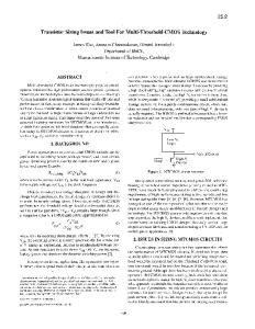
Weather cap may be required
Pressure relief valve
Long radius elbow
Body drain (see Note 1)
Support to resist weight and reaction forces
Low-point drain (see Note 2)
Nominal pipe diameter no less than valve inlet size Non-recoverable pressure losses not more than 3 percent of pressure relief valve set pressure
Vessel
Notes: 1.) See Section 8 for a discussion on the use of the valve body drain. 2.) Orient low point drainÑor weep holeÑaway from relief valve, structural steel, and operating area.
Figure 1ÑTypical Pressure-Relief Valve Installation: Atmospheric (Open) Discharge between the protected equipment and the pressure-relief valve should not exceed 3 percent of the set pressure of the valve except as permitted in 4.2.3 for pilot-operated pressurerelief valves. When a pressure-relief valve is installed on a process line, the 3 percent limit should be applied to the sum of the loss in the normally non-ßowing pressure-relief valve inlet pipe and the incremental pressure loss in the process line caused by the ßow through the pressure-relief valve. The pressure loss should be calculated using the rated capacity of the pressure-relief valve. Pressure losses can be reduced by rounding the entrance to the inlet piping, by reducing the inlet line length, or by enlarg-
ing the inlet piping. The nominal size of the inlet piping must be the same as or larger than the nominal size of the pressurerelief valve inlet connection as shown in Figures 1 through 3. Keeping the pressure loss below 3 percent becomes progressively more difÞcult at low pressures as the oriÞce size of a pressure-relief valve increases. An engineering analysis of the valve performance at higher inlet losses may permit increasing the allowable pressure loss above 3 percent. When a rupture disk device is used in combination with a pressure-relief valve, the pressure-drop calculation must include the additional pressure drop developed by the disk (see 4.6 for additional information on rupture disk devices).
--`,,``,,`,``,`,`,```,,`,`,````-`-`,,`,,`,`,,`---
COPYRIGHT 2003; American Petroleum Institute
Document provided by IHS Licensee=Fluor Corp/2110503106, User=, 09/30/2003 07:48:43 MDT Questions or comments about this message: please call the Document Policy Group at 1-800-451-1584.
SIZING, SELECTION, AND INSTALLATION OF PRESSURE-RELIEVING DEVICES IN REFINERIES / PART IIÑINSTALLATION
3
Bonnet vent piping for bellows type pressure relief valve, if required (see Note)
To closed system (self-draining)
Flanged spool piece, if required to elevate PRV Non-recoverable pressure losses not more than 3 percent of relief value set pressure
Nominal pipe diameter no less than valve inlet size
Vessel
Note: See Section 7 for a discussion on bonnet venting.
Figure 2ÑTypical Pressure-Relief Valve Installation: Closed System Discharge 4.2.3 Remote Sensing for Pilot-Operated Pressure-Relief Valves Remote sensing for pilot-operated pressure-relief valves can be utilized when there is excessive inlet pipe pressure loss or when the main valve must be located at a pressure source different from the pilot sensing point because of service limitations of the main valve (see Figure 6). 4.2.3.1 Inlet Pipe Loss Remote sensing permits the pilot to sense the system pressure upstream of the piping loss. Remote sensing may eliminate uncontrolled valve cycling or chattering for a pop action pilot-operated pressure-relief valve and will permit a modulating pilot-operated pressure-relief valve to achieve full lift at the required overpressure. Although remote sensing may eliminate valve chatter or permit a modulating pilot-operated pressure-relief valve to achieve full lift at the required overpressure, any pressure drop in the inlet pipe will reduce the relieving capacity.
4.2.3.2 Installation Guidelines Remote sensing lines should measure static pressure where the velocity is low. Otherwise, the pilot will sense an artiÞcially low pressure due to the effect of velocity. Ensure that the pilot sensing point is within the system protected by the main valve. For ßowing pilots, remote sensing lines shall be sized to limit the pressure loss to 3 percent of the set pressure based on the maximum ßow rate of the pilot at 110 percent of set pressure. Consult the manufacturer for size recommendations for the remote sensing line. For non-ßowing pilots, remote sensing lines with a ßow area of 0.070 in.2 (45 mm2) should be sufÞcient since no system medium ßows through this type of pilot when the main valve is open and relieving. Consult the manufacturer for remote sensing line size recommendations. Consider using pipe for remote sensing lines to ensure mechanical integrity. If a block valve is installed in the remote sensing line, the guidelines in Section 6 should be followed. A closed block valve in a remote sensing line renders the pressure-relief valve inoperative and may allow the valve to open.
--`,,``,,`,``,`,`,```,,`,`,````-`-`,,`,,`,`,,`---
COPYRIGHT 2003; American Petroleum Institute
Document provided by IHS Licensee=Fluor Corp/2110503106, User=, 09/30/2003 07:48:43 MDT Questions or comments about this message: please call the Document Policy Group at 1-800-451-1584.
4
API RECOMMENDED PRACTICE 520
Holder Rupture disc device
Rupture disc
Vessel
Figure 3ÑTypical Rupture Disk Device Installation: Atmospheric (Open) Discharge 4.2.3.3 Purge Systems Purge systems may be required for certain applications prone to plugging. Special considerations are required if purge systems are used. The manufacturer should be consulted for recommendations. 4.2.4 Configuration of Inlet Piping for PressureRelief Valves Avoid the installation of a pressure-relief valve at the end of a long horizontal inlet pipe through which there is normally no ßow. Foreign matter may accumulate, or liquid may be trapped, creating interference with the valveÕs operation or requiring more frequent valve maintenance. The inlet piping system to pressure-relief devices should be free-draining to prevent accumulation of liquid or foreign matter in the piping.
4.3 INLET STRESSES THAT ORIGINATE FROM STATIC LOADS IN THE DISCHARGE PIPING Improper design or construction of the discharge piping from a pressure-relief device can set up stresses that will be transferred to the pressure-relief device and its inlet piping. These stresses may cause a pressure-relief valve to leak or malfunction or may change the burst pressure of a rupture disk. The pressure-relief device manufacturer should be consulted about permissible loads. 4.3.1 Thermal Stresses Fluid ßowing from the discharge of a pressure-relief device may cause a change in the temperature of the discharge piping. A change in temperature may also be caused by prolonged exposure to the sun or to heat radiated from nearby equipment. Any change in the temperature of the discharge piping will cause a change in the length of the piping and may cause stresses that will be transmitted to the pressure-relief device and its inlet piping. The pressure-relief device should
--`,,``,,`,``,`,`,```,,`,`,````-`-`,,`,,`,`,,`---
COPYRIGHT 2003; American Petroleum Institute
Document provided by IHS Licensee=Fluor Corp/2110503106, User=, 09/30/2003 07:48:43 MDT Questions or comments about this message: please call the Document Policy Group at 1-800-451-1584.
--`,,``,,`,``,`,`,```,,`,`,````-`-`,,`,,`,`,,`---
SIZING, SELECTION, AND INSTALLATION OF PRESSURE-RELIEVING DEVICES IN REFINERIES / PART IIÑINSTALLATION
5
Pressure-loss limitation (see Note)
Pressure relief valve
Vessel
Note: See 4.2.2 for pressure-loss limitations when the pressure relief valve is installed on normally flowing process piping.
Figure 4ÑTypical Pressure-Relief Valve Mounted on Process Line be isolated from piping stresses through proper support, anchoring, or ßexibility of the discharge piping. 4.3.2 Mechanical Stresses Discharge piping should be independently supported and carefully aligned. Discharge piping that is supported by only the pressure-relief device will induce stresses in the pressurerelief device and the inlet piping. Forced alignment of the discharge piping will also induce such stresses. 4.4 INLET STRESSES THAT ORIGINATE FROM DISCHARGE REACTION FORCES The discharge of a pressure-relief device will impose a reaction force as a result of the ßowing ßuid (see Figure 7). This force will be transmitted into the pressure-relief device and also into the mounting nozzle and adjacent supporting vessel shell unless designed otherwise. The precise magnitude of the loading and resulting stresses will depend on the reaction force and the conÞguration of the piping system. The designer is responsible for analyzing the discharge system to determine if the reaction forces and the associated bending moments will cause excessive stresses on any of the components in the system. The magnitude of the reaction force will differ substantially depending on whether the installation is open or closed
COPYRIGHT 2003; American Petroleum Institute
discharge. When an elbow is installed in the discharge system to direct the ßuid up into a vent pipe, the location of the elbow and any supports is an important consideration in the analysis of the bending moments. 4.4.1 Determining Reaction Forces in an Open Discharge System 4.4.1.1 Vapor Discharge The following formula is based on a condition of critical steady-state ßow of a compressible ßuid that discharges to the atmosphere through an elbow and a vertical discharge pipe. The reaction force (F) includes the effects of both momentum and static pressure; thus, for any gas, vapor, or steam. In U.S. customary units, W kT F = --------- --------------------- + ( AP ) 366 ( k + 1 )M In metric units, kT F = 129W --------------------- + 0.1 ( AP ) ( k + 1 )M
Document provided by IHS Licensee=Fluor Corp/2110503106, User=, 09/30/2003 07:48:43 MDT Questions or comments about this message: please call the Document Policy Group at 1-800-451-1584.
6
API RECOMMENDED PRACTICE 520
Pressure relief valve Discharge valve
Inlet piping (see Note)
Vessel
Note: Inlet piping sized so that non-recoverable pressure losses from vessel to pressure relief valve inlet flange do not exceed 3 percent of valve set pressure.
Figure 5ÑTypical Pressure-Relief Valve Mounted on Long Inlet Pipe
4.4.1.2 Two-Phase Discharge
where F
=
reaction force at the point of discharge to the atmosphere, lbf [N],
W
=
ßow of any gas or vapor, lbm/hr [kg/s],
k
=
ratio of speciÞc heats (Cp/Cv) at the outlet conditions.
Cp =
speciÞc heat at constant pressure,
Cv
=
speciÞc heat at constant volume,
T
=
temperature at the outlet, ¡R [¡K],
M
=
molecular weight of the process ßuid,
A
=
area of the outlet at the point of discharge, in.2 [mm2],
P
=
static pressure within the outlet at the point of discharge, psig [barg].
The following formula can be used to determine the reaction force on inlet piping from an open discharge of a twophase ßuid. The formula assumes that the two-phase mixture is in homogenous ßow condition (no-slip). In U.S. customary units, 2
W x (1 Ð x) F = --------------------------------- + ---------------- + A ( P e Ð P a ) 6 rl 2.898E10 A r g In metric units, 2
W A x (1 Ð x) F = ----------------- ----- + ---------------- + ------------ ( P e Ð P a ) 12.96A r g 1000 rl
--`,,``,,`,``,`,`,```,,`,`,````-`-`,,`,,`,`,,`---
COPYRIGHT 2003; American Petroleum Institute
Document provided by IHS Licensee=Fluor Corp/2110503106, User=, 09/30/2003 07:48:43 MDT Questions or comments about this message: please call the Document Policy Group at 1-800-451-1584.
SIZING, SELECTION, AND INSTALLATION OF PRESSURE-RELIEVING DEVICES IN REFINERIES / PART IIÑINSTALLATION
7
Pilot
Main valve Integral pressure sensing
Optional remote pressure sensing (see 4.2.3)
Vessel
Figure 6ÑTypical Pilot-Operated Pressure-Relief Valve Installation where F
=
reaction force at the point of discharge to the atmosphere, lbf [N],
W
=
ßowrate, lbm/hr [kg/hr],
x
=
weight fraction vapor at exit conditions,
rg
=
vapor density at exit conditions, lbm/ft3 [kg/m3],
rl
=
liquid density at exit conditions, lbm/ft3 [kg/m3],
A
=
area of the outlet at the point of discharge, in.2 [mm2],
Pe
=
absolute pressure at pipe exit, psia [kPa],
Pa
=
absolute ambient pressure, psia [kPa].
--`,,``,,`,``,`,`,```,,`,`,````-`-`,,`,,`,`,,`---
COPYRIGHT 2003; American Petroleum Institute
Document provided by IHS Licensee=Fluor Corp/2110503106, User=, 09/30/2003 07:48:43 MDT Questions or comments about this message: please call the Document Policy Group at 1-800-451-1584.
8
API RECOMMENDED PRACTICE 520
F (see Note 2) --`,,``,,`,``,`,`,```,,`,`,````-`-`,,`,,`,`,,`---
A (see Note 2)
Vent pipe
Pressure relief valve
Long radius elbow
Support to resist weight and reaction forces (see Note 1)
Vessel
Notes: 1. The support should be located as close as possible to the centerline of the vent pipe. 2. F = reaction force; A = cross-sectional area.
Figure 7ÑTypical Pressure-Relief Valve Installation with Vent Pipe 4.4.2 Determining Reaction Forces in a Closed Discharge System Pressure-relief devices that relieve under steady-state ßow conditions into a closed system usually do not transfer large forces and bending moments to the inlet system, since changes in pressure and velocity within the closed system components are small. Only at points of sudden expansion in the discharge piping will there be any signiÞcant inlet piping reaction forces to be calculated. Closed discharge systems, however, do not lend
COPYRIGHT 2003; American Petroleum Institute
themselves to simpliÞed analytical techniques. A complex time history analysis of the piping system may be required to obtain the reaction forces and associated moments that are transferred to the inlet piping system. 4.5 ISOLATION VALVES IN INLET PIPING Isolation valves located in the inlet piping to pressurerelief devices shall be in accordance with the guidelines in Section 6.
Document provided by IHS Licensee=Fluor Corp/2110503106, User=, 09/30/2003 07:48:43 MDT Questions or comments about this message: please call the Document Policy Group at 1-800-451-1584.
SIZING, SELECTION, AND INSTALLATION OF PRESSURE-RELIEVING DEVICES IN REFINERIES / PART IIÑINSTALLATION
A rupture disk device may be used as the sole pressurerelief device, or it may be installed between a pressure-relief valve and the vessel or on the downstream side of a pressurerelief valve (see Figure 8). When a rupture disk device is used between the pressurerelief valve and the protected vessel, the space between the rupture disk and the pressure-relief valve shall have a free vent, pressure gauge, trycock, or other suitable telltale indicator. A non-vented space with a pressure gage without alarms or other indication devices is not recommended as a suitable telltale indicator. Users are warned that a rupture disk will not burst in tolerance if back pressure builds up in a non-vented space between the rupture disk and the pressure-relief valve, which will occur should leakage develop in the rupture disk due to corrosion or other cause. Only non-fragmenting rupture disk devices may be used beneath a pressure-relief valve. Rupture disks may not be available in all sizes at lower pressures; therefore, for these low-pressure applications the available rupture disk may have to be larger than the nominal size of the inlet piping and pressure-relief valve. Refer to API RP 520, Part I for additional information related to the combination capacity factor when a rupture disk is installed in combination with a pressure-relief valve. 4.7 PROCESS LATERALS CONNECTED TO INLET PIPING OF PRESSURE-RELIEF VALVES Process laterals should generally not be connected to the inlet piping of pressure-relief valves (see Figure 9). Exceptions should be analyzed carefully to ensure that the allowable pressure drop at the inlet of the pressure-relief valve is not exceeded under simultaneous conditions of rated ßow through the pressure-relief valve and maximum possible ßow through the process lateral. 4.8 TURBULENCE IN PRESSURE-RELIEF DEVICE INLETS See 9.3 for information regarding the effects of turbulence on pressure-relief valves.
5 Discharge Piping From Pressure-Relief Devices 5.1 GENERAL REQUIREMENTS For general requirements for discharge piping, see Figures 1, 2, 7, and 10. The discharge piping installation must provide for proper pressure-relief device performance and adequate drainage (free-draining systems are preferredÑsee Section 8). Consideration should be given to the type of discharge system used, the back pressure on the pressure-relief device, and the set-pressure relationship of the pressure-relief devices in the system.
COPYRIGHT 2003; American Petroleum Institute
Auto-refrigeration during discharge can cool the outlet of the pressure-relief device and the discharge piping to the point that brittle fracture can occur. Piping design, including material selection, must consider the expected discharge temperature. 5.2 SAFE DISPOSAL OF RELIEVING FLUIDS For a comprehensive source of information about the safe disposal of various relieving ßuids, see API RP 521. 5.3 BACK PRESSURE LIMITATIONS AND SIZING OF PIPE When discharge piping for pressure-relief valves is designed, consideration should be given to the combined effect of superimposed and built-up back pressure on the operating characteristics of the pressure-relief devices. The discharge piping system should be designed so that the back pressure does not exceed an acceptable value for any pressure-relief device in the system. See API RP 520 Part I for limitations on back pressure. When rupture disks are used as the sole relieving device and the discharge is to a closed system, the effect of the superimposed back pressure on the bursting pressure for the disk must be considered. The rated capacity of a conventional spring loaded, balanced spring loaded or pop action pilot-operated pressurerelief valve should typically be used to size the atmospheric vent piping or the discharge line from the pressure-relief valve to the relief header. Common relief header piping in closed discharge systems should be sized using the protected systemÕs required relieving capacity. For a modulating pilot-operated pressure-relief valve, the discharge piping can be sized using the required relieving capacity of the system that the valve is protecting. Whenever the atmospheric vent, discharge piping or common relief header piping is sized using the systemÕs required relieving capacity instead of the rated capacity of the valve, the back pressure should be re-checked whenever changes are made to the process that effect the required relieving capacity of the system the valve is protecting. Additional information on sizing of discharge piping systems for vapor or gas service is covered in API RP 521. 5.4 CONSIDERATIONS FOR PILOT-OPERATED PRESSURE-RELIEF VALVES Superimposed back pressure that exceeds the inlet pressure of a pilot-operated pressure-relief valve can cause the main valve to open, allowing reverse ßow through the main valve. For example, backßow can occur if several pressure-relief valves have their outlets manifolded into a common discharge header, and one or more of these valves is discharging while another is connected to a system with a lower inlet pressure. An accessory should be speciÞed that would prevent such backßow.
Document provided by IHS Licensee=Fluor Corp/2110503106, User=, 09/30/2003 07:48:43 MDT Questions or comments about this message: please call the Document Policy Group at 1-800-451-1584.
--`,,``,,`,``,`,`,```,,`,`,````-`-`,,`,,`,`,,`---
4.6 RUPTURE DISK DEVICES IN COMBINATION WITH PRESSURE-RELIEF VALVES
9
10
API RECOMMENDED PRACTICE 520
Pressure relief valve Discharge piping
Rupture disk device (see Note 1)
Free vent or telltale indicator (see Note 2)
Non-recoverable pressure losses not more than 3 percent of pressure relief valve set pressure
Vessel
Notes: 1.) Non-fragmenting rupture disk design. 2.) The space between the rupture disk and pressure relief valve must be vented or provided with a suitable telltale indicator. See 4.6 for additional guidelines.
Figure 8ÑTypical Rupture Disk Device in Combination with Relief Valve: Inlet Side Installation --`,,``,,`,``,`,`,```,,`,`,````-`-`,,`,,`,`,,`---
COPYRIGHT 2003; American Petroleum Institute
Document provided by IHS Licensee=Fluor Corp/2110503106, User=, 09/30/2003 07:48:43 MDT Questions or comments about this message: please call the Document Policy Group at 1-800-451-1584.
SIZING, SELECTION, AND INSTALLATION OF PRESSURE-RELIEVING DEVICES IN REFINERIES / PART IIÑINSTALLATION
11
Pressure relief valve
Avoid process laterals (see note)
Vessel
Note: See 4.7 for cautions related to process laterals installed on pressure relief inlet piping.
Figure 9ÑAvoiding Process Laterals Connected to Pressure-Relief Valve Inlet Piping 5.5 STRESSES IN DISCHARGE PIPING DURING RELEASE The reaction forces and stresses that originate in the downstream piping as a result of the release of a pressure-relief device are typically not signiÞcant once ßow is established and has reached steady state conditions, due to small changes in pressure and velocity within the closed system components. However, large forces may result if there are sudden pipe expansions within the system or as a result of unsteady ßow conditions during the initial activation of the relief device. Additionally, large reaction forces can be created at elbows as a result of two-phase ßuid ßow in the slug ßow regime. The design of ßare header piping in closed discharge systems should be in accordance with ASME B31.3. The design of ßare header piping is not amenable to simpliÞed analytical techniques, consequently, assistance by individuals knowledgeable in pipe stress analysis is recommended. A complex
dynamic analysis of the system may be required. API RP 521 gives additional guidance on the design of ßare header piping. 5.6 ISOLATION VALVES IN THE DISCHARGE PIPING Isolation valves located in the discharge piping system shall be in accordance with the guidelines provided in Section 6. 5.7 RUPTURE DISKS INSTALLED AT OUTLET OF PRESSURE-RELIEF VALVES A rupture disk device may be installed on the outlet of a pressure-relief valve to protect the valve from atmospheric or downstream ßuids. Consideration shall be given to the pressure-relief valve design so that it will open at its proper pressure setting regardless of any back pressure that may accumulate between the valve and rupture disk. See UG-127 of the ASME Boiler and Pressure Vessel Code, Section VIII for other requirements and considerations.
--`,,``,,`,``,`,`,```,,`,`,````-`-`,,`,,`,`,,`---
COPYRIGHT 2003; American Petroleum Institute
Document provided by IHS Licensee=Fluor Corp/2110503106, User=, 09/30/2003 07:48:43 MDT Questions or comments about this message: please call the Document Policy Group at 1-800-451-1584.
12
API RECOMMENDED PRACTICE 520
Isolation valve with provision for car sealing or locking open (not required for atmospheric discharge, see Note 1)
Bonnet vent piping for bellows type pressure relief valves, if required (see Section 7)
To closed system or atmospheric piping
Bleed valve installed on valve body (see Note 2)
Bleed valve Isolation valve with provision for car sealing or locking open
Non-recoverable pressure losses not more than 3 percent of set pressure
Flanged spool piece, if required to elevate PRV
Notes: 1.) See Section 6 for the use of isolation valves in pressure relief system piping. 2.) Alternatively, a pipe spool with bleed may be provided.
Figure 10ÑTypical Pressure-Relief Device Installation with an Isolation Valve --`,,``,,`,``,`,`,```,,`,`,````-`-`,,`,,`,`,,`---
COPYRIGHT 2003; American Petroleum Institute
Document provided by IHS Licensee=Fluor Corp/2110503106, User=, 09/30/2003 07:48:43 MDT Questions or comments about this message: please call the Document Policy Group at 1-800-451-1584.
SIZING, SELECTION, AND INSTALLATION OF PRESSURE-RELIEVING DEVICES IN REFINERIES / PART IIÑINSTALLATION
6
Isolation (Stop) Valves in PressureRelief Piping
6.1 GENERAL Isolation block valves may be used for maintenance purposes to isolate a pressure-relief device from the equipment it protects or from its downstream disposal system. Since improper use of an isolation valve may render a pressure-relief device inoperative, the design, installation, and administrative controls placed on these isolation block valves should be carefully evaluated to ensure that plant safety is not compromised. A pressure-relief device shall not be used as a block valve to provide positive isolation. 6.2 APPLICATION If a pressure-relief device has a service history of leakage, plugging, or other severe problems that affect its performance, isolation and sparing of the pressure-relief device may be provided. This design strategy permits the pressure-relief device to be inspected, maintained, or repaired without shutting down the process unit. However, there are potential hazards associated with the use of isolation valves. The ASME Boiler and Pressure Vessel Code, Section VIII, Appendix M, discusses proper application of these valves and the administrative controls that must be in place when isolation block valves are used. Local jurisdictions may have other requirements. Additional examples of isolation valve installations are given in 6.4. 6.3 ISOLATION VALVE REQUIREMENTS In addition to previously noted inlet and outlet pressure drop restrictions, all isolation valves located in relief system piping shall meet the requirements provided in 6.3.1 and 6.3.2. 6.3.1 Inlet Isolation Valves a. Valves shall be full bore. ASME Section VIII Appendix M recommends the use of full area isolation (stop) valves. Mandatory paragraph UG-135 (b)(1), of ASME Section VIII, requires that the opening through all pipe and Þttings between a pressure vessel and its pressure-relief valve shall have the area of the pressure-relief device inlet. It is therefore recommended that the minimum ßow area in the isolation valve be equal to or greater than the inlet area of the pressure-relief valve. The minimum ßow area of the isolation valve and the inlet area of the pressurerelief valve can be obtained from the isolation valve manufacturer and the pressure-relief valve manufacturer. b. Valves shall be suitable for the line service classiÞcation. c. Valves shall have the capability of being locked or carsealed open.
d. When gate valves are used, they should be installed with stems oriented horizontally or, if this is not feasible, the stem could be oriented downward to a maximum of 45¡â from the horizontal to keep the gate from falling off and blocking the ßow. e. A bleed valve should be installed between the isolation valve and the pressure-relief device to enable the system to be safely depressurized prior to performing maintenance. This bleed valve can also be used to prevent pressure build-up between the pressure-relief device and the closed outlet isolation valve. f. Consideration should be given to using an interlocking system between the inlet and outlet isolation valves to assist with proper sequencing. g. Consideration should be given to painting the isolation valve a special color or providing other identiÞcation. When placing the pressure-relief device into service, it is recommended to gradually open the isolation valve. This ramping up of system pressure can help prevent unwanted opening of a valve seat due to the momentum of the ßuid. The inlet valve must be open fully. Typical installations of isolation valves mounted at the inlet of pressure-relief devices are shown in Figures 11 through 13. 6.3.2 Outlet Isolation Valves a. Valves shall be full bore. ASME Section VIII Appendix M recommends the use of full area isolation (stop) valves. To help minimize the built-up back pressure, it is recommended that the minimum ßow area in the outlet isolation valve be equal to or greater than the outlet area of the pressure-relief valve. The minimum ßow area of the outlet isolation valve and the outlet area of the pressure-relief valve can be obtained from the isolation valve manufacturer and the pressure-relief valve manufacturer respectively. b. Valves shall be suitable for line service classiÞcation. c. Valves shall have the capability of being locked or carsealed open. This outlet isolation shall never be closed while the vessel is in operation without using an inlet isolation valve that has Þrst been closed with the space between the inlet isolation valve and the pressure-relief valve adequately depressured. d. A bleed valve should be installed between the outlet isolation valve and pressure-relief device to enable the system to be safely depressurized prior to performing maintenance. This bleed valve can also be used to prevent pressure build-up between the pressure-relief device and the closed outlet isolation valve. e. Consideration should be given to using an interlocking system between the inlet and outlet isolation valves to assist with proper sequencing. f. Consideration should be given to painting the isolation valve a special color or providing other identiÞcation.
--`,,``,,`,``,`,`,```,,`,`,````-`-`,,`,,`,`,,`---
COPYRIGHT 2003; American Petroleum Institute
13
Document provided by IHS Licensee=Fluor Corp/2110503106, User=, 09/30/2003 07:48:43 MDT Questions or comments about this message: please call the Document Policy Group at 1-800-451-1584.
14
API RECOMMENDED PRACTICE 520
To closed (isolation valving required) or atmospheric discharge system
Non-recoverable pressure losses not more than 3 percent of set pressure Typical bleed valve
VESSEL
Figure 11ÑTypical Pressure-Relief Device Installation for 100 Percent Spare Relieving Capacity When the outlet isolation valve is used in conjunction with an inlet isolation valve, upon commissioning the pressurerelief device, the outlet isolation valve shall be opened fully prior to the inlet isolation valves. A typical installation of inlet and outlet isolation valves for pressure-relief valves are shown in Figure 10.
6.3.3 Installation of Spare Relief Capacity In corrosive and fouling services, or other services which may require frequent pressure-relief device inspection and testing, consideration should be given to the installation of an additional relief device, so that 100 percent design relieving capacity is available while any pressure-relief device is out of service. See examples shown in Figures 11, 12, and 13. Con-
--`,,``,,`,``,`,`,```,,`,`,````-`-`,,`,,`,`,,`---
COPYRIGHT 2003; American Petroleum Institute
Document provided by IHS Licensee=Fluor Corp/2110503106, User=, 09/30/2003 07:48:43 MDT Questions or comments about this message: please call the Document Policy Group at 1-800-451-1584.
15
To closed (isolation valving required) or atmospheric discharge system
Typical bleed valve
Typical isolation valve with provision for car sealing or locking open (see Section 6)
Typical bleed valve
Non-recoverable pressure losses not more than 3 percent of set pressure
VESSEL
Figure 12ÑAlternate Pressure-Relief Device Arrangement for 100 Percent Spare Relieving Capacity sideration should be given to storing the spare pressure-relief valves until needed, to preserve its integrity and allow bench testing just prior to installation. When spare relief devices are provided, a mechanical interlock or administrative controls shall be provided which manages proper opening and closing sequences of the isolation valves to ensure that overpressure protection of the vessel or equipment is not compromised.
COPYRIGHT 2003; American Petroleum Institute
Typically the inlet isolation valves for spare relief devices are closed and the outlet isolation valves are open. The outlet isolation valve for spare relief devices can be closed during operation if exposure to the ßuid is a concern, however, the pressure temperature rating of the pressure-relief device outlet, the outlet isolation valve and intervening piping should be suitable for the conditions upstream of the relief device in case of leakage. Another method to protect the pressure-relief
Document provided by IHS Licensee=Fluor Corp/2110503106, User=, 09/30/2003 07:48:43 MDT Questions or comments about this message: please call the Document Policy Group at 1-800-451-1584.
--`,,``,,`,``,`,`,```,,`,`,````-`-`,,`,,`,`,,`---
SIZING, SELECTION, AND INSTALLATION OF PRESSURE-RELIEVING DEVICES IN REFINERIES / PART IIÑINSTALLATION
API RECOMMENDED PRACTICE 520
To close (isolation valving required) or atmospheric discharge system
Non-recoverable pressure losses not more than 3 percent of set pressure
Typical bleed valve
Positive indication of active relieving device
Vessel
Figure 13ÑAlternate Pressure-Relief Device Installation Arrangement for 100 Percent Spare Relieving Capacity device from discharge system ßuids without closing the outlet isolation valve is to provide a purge. Three-way changeover valves are acceptable in spare relief capacity applications provided the installation meets the size and inlet pressure drop requirements (see 6.3.4). 6.3.4 Three-way Changeover Valves for Dual Pressure-Relief Device Installations
sure-relief device installations. Such installations provide 100 percent of the design relieving capacity with one pressurerelief device while a relief device is out of service. The second pressure-relief device may be permanently mounted on the three-way changeover valve or may be stored until needed to preserve its integrity and allow bench testing just prior to installation. Three types of changeover valves are available: a
Three-way changeover valves are available, which are designed speciÞcally for isolation valve service of dual pres-
COPYRIGHT 2003; American Petroleum Institute
Document provided by IHS Licensee=Fluor Corp/2110503106, User=, 09/30/2003 07:48:43 MDT Questions or comments about this message: please call the Document Policy Group at 1-800-451-1584.
--`,,``,,`,``,`,`,```,,`,`,````-`-`,,`,,`,`,,`---
16
SIZING, SELECTION, AND INSTALLATION OF PRESSURE-RELIEVING DEVICES IN REFINERIES / PART IIÑINSTALLATION
Figure 14ÑThree-Way Changeover ValveÑShuttle Type
Figure 15ÑThree-Way Changeover ValveÑRotor Type --`,,``,,`,``,`,`,```,,`,`,````-`-`,,`,,`,`,,`---
COPYRIGHT 2003; American Petroleum Institute
Document provided by IHS Licensee=Fluor Corp/2110503106, User=, 09/30/2003 07:48:43 MDT Questions or comments about this message: please call the Document Policy Group at 1-800-451-1584.
17
API RECOMMENDED PRACTICE 520
three-way ball valve combined with piping on the inlet and outlet, the shuttle type (see Figure 14) and the rotor type (see Figure 15). a. Three-way changeover valves, used for pressure-relief valve installations, shall be sized to assure compliance with the inlet loss requirements of 4.2. Some three-way changeover valves are designed with minimum ßow areas equal to or greater than the inlet area of a pressure-relief valve designed for that line size. Other designs, however, may have to be speciÞed one line size larger than the pressure-relief valve to minimize inlet pressure losses. b. The three-way changeover valve should be designed to prevent both pressure-relief devices from being isolated at any time during its switchover operation. c. A positive indication of which pressure-relief device is active should be a required accessory for the three-way changeover valve. d. A bleed valve shall be installed between the inlet isolation valve and an isolated pressure-relief device to enable the inlet to the isolated pressure-relief valve to be safely depressurized prior to performing maintenance. e. Individual isolation valves may be used on the outlet side of pressure-relief devices that are mounted on an inlet threeway changeover. When using individual outlet isolation valves the recommendations of 6.3.2 should be followed. f. Three-way valves may also be used for outlet isolation. Designs are available that will minimize the effects of builtup back pressure when using the same pipe size as the outlet of the pressure-relieving device. All other recommendations of 6.3.2b Ð d should be followed. g. Isolation valves shall have the capability of being locked or car-sealed in position. Only an authorized person may break the seal and operate the valve (See 6.3.1c and 6.3.2c). Mechanical interlocks and/or management control procedures shall be provided which will assure the proper opening and closing sequences of the inlet and outlet isolation valves. 6.3.5 Use of Ball Valves as Three-way Changeover Valve Ball valves are available in a variety of conÞgurations as shown in Figure 16. The two seat L-port conÞguration is the most commonly used conÞguration for relief device selector service. Due to the variety of conÞgurations, caution should be taken so that the proper conÞguration is speciÞed, the ports properly marked, and the valve properly installed. 6.4 EXAMPLES OF ISOLATION VALVE INSTALLATIONS An isolation valve downstream of a pressure-relief device may be installed at battery limits of process units (see Figure 17). The purpose of battery limit isolation valves is to allow process units to be removed from service for maintenance
COPYRIGHT 2003; American Petroleum Institute
while other process units discharging into the main plant ßare header remain in service. Similarly, relief system isolation valves may be used for equipment such as compressors, salt dryers, or coalescers, which are spared and need to be shut down for maintenance while spare equipment remains online (see Figure 18). 6.5 ADMINISTRATIVE CONTROLS RELATED TO ISOLATION VALVES Administrative controls shall be in place that will prohibit the inappropriate closing of isolation valves in pressurerelief system piping. These controls should require that the opening and closing of the isolation valves be done by an authorized person. An updated list should be kept of all isolation valves located in pressure-relief system piping which could isolate pressure-relief valves. Documentation of the required position and reason for the lock or seal should be provided. Periodic inspections of isolation valves located in pressure-relief system piping should be made which verify the position of isolation valves and the condition of the locking or sealing device.
7 Bonnet or Pilot Vent Piping 7.1 GENERAL Depending on the type of pressure-relief valve, proper venting of the bonnets and pilots is required to ensure proper operation of the valve. 7.2 CONVENTIONAL VALVES Bonnets on conventional pressure-relief valves can either be opened or closed type bonnets and do not have any special venting requirements. Open bonnets are often used in steam service and are directly exposed to the atmosphere. Valves with closed bonnets are internally vented to the pressure-relief valve discharge. The bonnet normally has a tapped vent that is closed off with a threaded plug. 7.3 BALANCED BELLOWS VALVES Balanced bellows pressure-relief valves are utilized in applications where it is necessary to minimize the effect of back pressure on the set pressure and relieving capacity of the valve. This is done by balancing the effect of the back pressure on the top and bottom surfaces of the disc. This requires the bonnet to operate at atmospheric pressure. The bonnets of balanced bellows pressure-relief valves must always be vented to ensure proper functioning of the valve. The bonnet vent may also provide a visual indication in the event of a bellows failure. The vent must be designed to avoid plugging caused by ice, insects, or other obstructions. When the ßuid is ßammable, toxic, or corrosive, the bonnet vent may need to be piped to a safe location.
Document provided by IHS Licensee=Fluor Corp/2110503106, User=, 09/30/2003 07:48:43 MDT Questions or comments about this message: please call the Document Policy Group at 1-800-451-1584.
--`,,``,,`,``,`,`,```,,`,`,````-`-`,,`,,`,`,,`---
18
SIZING, SELECTION, AND INSTALLATION OF PRESSURE-RELIEVING DEVICES IN REFINERIES / PART IIÑINSTALLATION
Number of seats
2
4
4
Port arrangements
Figure 16ÑThree-Way Changeover ValveÑBall Types
Process unit flare # header block valve # (See 6.4)
Battery limit
Process unit relief # header (self draining)
Pressure relief# valve installation# (See Figs. 11 and 12) Isolation blind point# (See Figure 9)
Pressure Relief Valve Installation (See Figs. 2 and 10)
Pressure# Vessel A
Pressure# Vessel B
Figure 17Ñ Typical Flare Header Block Valves --`,,``,,`,``,`,`,```,,`,`,````-`-`,,`,,`,`,,`---
COPYRIGHT 2003; American Petroleum Institute
Document provided by IHS Licensee=Fluor Corp/2110503106, User=, 09/30/2003 07:48:43 MDT Questions or comments about this message: please call the Document Policy Group at 1-800-451-1584.
19
20
API RECOMMENDED PRACTICE 520
Isolation block valves (see 6.4)
From spare compressor
Compressor flare headers
Isolation blind points
Pulsation dampeners
Compressor
Process unit flare header 1
2
3
First stage
Second stage
Third stage
Pulsation dampeners
Figure 18ÑTypical Isolation Block Valves for Spare Compressor 7.4 BALANCED PISTON VALVES
7.5 PILOT-OPERATED VALVES
Balanced piston pressure-relief valves are utilized in applications to minimize the effect of back pressure, similar to the balanced bellows valve. Proper operation depends on cancellation of the back pressure effect on opposing faces of the valve disc and balance piston. Since the piston area is equal to the nozzle seat area, the spring must operate at atmospheric pressure. Because of the ßow of system media past the piston, the bonnets of balanced piston valves should always be vented to atmosphere at a safe location. The amount of ßow past the piston into the bonnet depends on the pressure differential between the valve outlet and bonnet. In an installation where superimposed back pressure or built-up back pressure is high, the ßow past the piston could be substantial. This factor must be considered in the design of the bonnet venting.
The pilot is often vented to the atmosphere under operating conditions, since the discharge during operation is small. When vent discharge to the atmosphere is not permissible, the pilot should be vented either to the discharge piping or through a supplementary piping system to a safe location. When vent piping is designed, avoid the possibility of back pressure on the pilot unless the pilot is a balanced design.
8 Drain Piping 8.1 INSTALLATION CONDITIONS THAT REQUIRE DRAIN PIPING Discharge piping from pressure-relief devices must be drained properly to prevent the accumulation of liquids on the downstream side of the pressure-relief device. The outlet piping to closed systems should be self-draining to a liquid disposal point, thereby eliminating the need for a physical drain
--`,,``,,`,``,`,`,```,,`,`,````-`-`,,`,,`,`,,`---
COPYRIGHT 2003; American Petroleum Institute
Document provided by IHS Licensee=Fluor Corp/2110503106, User=, 09/30/2003 07:48:43 MDT Questions or comments about this message: please call the Document Policy Group at 1-800-451-1584.
SIZING, SELECTION, AND INSTALLATION OF PRESSURE-RELIEVING DEVICES IN REFINERIES / PART IIÑINSTALLATION
21
Inlet flange --`,,``,,`,``,`,`,```,,`,`,````-`-`,,`,,`,`,,`---
Inlet pipe Rounded entry branch connection Flow
Run pipe
D (see Note)
Note: D is typically not less than 10 pipe diameters from any device that causes unstable flow.
Figure 19ÑTypical Installation Avoiding Unstable Flow Patterns at Pressure-Relief Valve Inlet or drain piping from the discharge piping or the pressurerelief valve. When the discharge piping is not self-draining and the device is located where liquids could accumulate at the outlet, drain piping should be provided. This drain piping could be installed on the discharge piping or installed at the pressurerelief valve in the body connection provided for this purpose. Since a rupture disk is a differential pressure device, care must be taken to ensure that the disk pressure is not elevated by accumulation of ßuids on the vent (atmospheric) side of the rupture disk. Periodic veriÞcation should be made that the rupture disk discharge line is clear and free from rainwater or other ßuids that will cause the rupture disk to activate above its marked burst pressure. Proper drainage, as indicated above, is appropriate as are Òpipe capsÓ or Òpipe coversÓ in those instances where the disk is vented directly to atmo-
COPYRIGHT 2003; American Petroleum Institute
sphere with the potential of rainwater accumulation on the vent (atmospheric) side of the disk. 8.2 SAFE PRACTICE FOR INSTALLATION OF DRAIN PIPING Since drain piping becomes part of the entire venting system, precautions that apply to the discharge system apply similarly to the drain piping. The drain-piping installation must not adversely affect the valve performance, and ßammable, toxic, or corrosive ßuids must be piped to a safe location. When the drain piping is piped to grade and ends with a drain valve, consideration should be given to the installation of a sight glass to allow operating personnel to observe whether or not liquid is accumulating in the drain piping. Additional consideration should be given to heat tracing the drain piping to grade since this is a dead leg that is subject to freezing in cold climates.
Document provided by IHS Licensee=Fluor Corp/2110503106, User=, 09/30/2003 07:48:43 MDT Questions or comments about this message: please call the Document Policy Group at 1-800-451-1584.
22
API RECOMMENDED PRACTICE 520
9 Pressure-Relief Device Location and Position 9.1 INSPECTION AND MAINTENANCE For optimum performance, pressure-relief devices must be serviced and maintained regularly. Details for the care and servicing of speciÞc pressure-relief devices are provided in the manufacturerÕs maintenance bulletins and in API RP 576. Pressure-Relief devices should be located for easy access, removal, and replacement so that servicing can be properly performed. SufÞcient working space should be provided around the pressure-relief device. 9.2 PROXIMITY TO PRESSURE SOURCE The pressure-relief device should normally be placed close to the protected equipment so that the inlet pressure losses to the device are within the allowable limits. For example, where protection of a pressure vessel is involved, mounting the pressure-relief device directly on a nozzle on top of the vessel may be necessary. However, on installations that have pressure ßuctuations at the pressure source (as with valves on a positive displacement compressor discharge) that peak close to the set pressure of the pressure-relief valve or burst pressure of a rupture disk, the pressure-relief device should be located farther from the source and in a more stable pressure region (see Section 4 for information related to this subject).
9.3.3 Other Valves and Fittings Proximity to other Þttings, such as elbows, may create turbulent areas that could result in adverse performance of pressure-relief devices. 9.4 MOUNTING POSITION Pressure-relief valves should be mounted in a vertical upright position. Installation of a pressure-relief valve in other than a vertical upright position may adversely affect its operation. The valve manufacturer should be consulted about any other mounting position, since mounting a pressure-relief valve in other positions may cause a shift in the set pressure and a reduction in the degree of seat tightness. Additionally, another position may permit liquids to collect in the spring bonnet. SolidiÞcation of these liquids around the spring may interfere with the valve operation. Rupture disk devices may be installed vertically or horizontally. Inlet and discharge piping must be adequately supported and aligned to prevent excessive loads due to the weight of piping components or applied moments. 9.5 TEST OR LIFTING LEVERS
Pressure-relief devices should not be located where unstable ßow patterns are present (see Figure 19). The branch entrance where the relief device inlet piping joins the main piping run should have a well-rounded, smooth corner that minimizes turbulence and resistance to ßow. In many instances, the next larger size branch connection will be required at the inlet to the pressure-relief valve (see Figure 19). When pressure-relief branch connections are mounted near equipment that can cause unstable ßow patterns, the branch connection should be mounted downstream at a distance sufÞcient to avoid the unstable ßow. Examples of devices that cause unstable ßow are discussed in 9.3.1 through 9.3.3.
Test or lifting levers should be provided on pressure-relief valves as required by the applicable code. Where levers are provided, they should hang downward, and the lifting fork must not contact the lifting nuts on the valve spindle. Uploads caused by the lifting-mechanism bearing on the spindle will cause the valve to open below the set pressure. The lifting mechanism should be checked to ensure that it does not bind on the valve spindle. Where it is necessary to have the test lever in other than a vertical position, or where the test lever is arranged for remote manual operation, the lever should be counterbalanced so that the lifting mechanism, unless actuated, does not exert any force on the valve spindle lifting nut. In lieu of lifting levers for pilot-operated pressure-relief valves, means may be speciÞed for connecting and applying adequate pressure to the pilot to verify that the moving parts critical to proper operation are free to move.
9.3.1 Reducing Stations
9.6 HEAT TRACING AND INSULATION
Pressure-relief devices are often used to protect piping downstream from pressure reducing valves, where unstable ßow usually occurs. Other valves and appurtenances in the system may also disturb the ßow. This condition cannot be evaluated readily, but unstable ßow at valve inlets tends to generate instability.
For materials that are highly viscous, materials that could result in corrosion upon cooling, or materials that could potentially solidify in pressure-relief devices, adequate heat tracing or insulation should be provided for both inlet and outlet piping to pressure-relief devices, as well as remote sensing lines for pilot-operated pressure-relief valves. Ensure that any discharge or vent port are not covered when the valve is insulated. The reliability of the tracing system must be maintained in order to ensure proper operation of the pressure-relief device.
9.3 PROXIMITY TO OTHER EQUIPMENT
--`,,``,,`,``,`,`,```,,`,`,````-`-`,,`,,`,`,,`---
9.3.2 Orifice Plates and Flow Nozzles Proximity to oriÞce plates and ßow nozzles may cause adverse operation of the pressure-relief devices.
COPYRIGHT 2003; American Petroleum Institute
Document provided by IHS Licensee=Fluor Corp/2110503106, User=, 09/30/2003 07:48:43 MDT Questions or comments about this message: please call the Document Policy Group at 1-800-451-1584.
SIZING, SELECTION, AND INSTALLATION OF PRESSURE-RELIEVING DEVICES IN REFINERIES / PART IIÑINSTALLATION
10 Bolting and Gasketing 10.1 CARE IN INSTALLATION Before a pressure-relief device is installed, the ßanges on the pressure-relief valve or rupture disk holder and the mounting nozzle should be thoroughly cleaned to remove any foreign material that may cause leakage. Where pressurerelief devices are too heavy to be readily lifted by hand, the use of proper handling devices will avoid damage to the ßange gasket facing. Ring joint and tongue-and-groove joint facings should be handled with extreme care so that the mating sections are not damaged. 10.2 PROPER GASKETING AND BOLTING FOR SERVICE REQUIREMENTS The gaskets used must be dimensionally correct for the speciÞc ßanges; they must fully clear the pressure-relief device inlet and outlet openings. Gaskets, ßange facings, and bolting should meet the service requirements for the pressure and temperature involved. This information can be obtained by referring to other national standards and to manufacturersÕ technical catalogs. When a rupture disk device is installed in the pressurerelief system, the ßange gasket material and bolting procedures may be critical. The disk manufacturerÕs instructions should be followed for proper performance (see Appendix A).
11 Multiple Pressure-Relief Valves with Staggered Settings Normal practice is to size a single pressure-relief valve to handle the maximum relief from a piece of equipment. However, for some systems, only a fraction of that amount must be relieved through the pressure-relief valve during mild upsets. If the ßuid volume under a pressure-relief valve is insufÞcient to sustain the ßow, the valve operation will be cyclic and will result in poor performance. The valveÕs ability to reseat tightly may be affected. When capacity variations are frequently encountered in normal operation, one alternate is the use of multiple, smaller pressure-relief valves with staggered settings. With this arrangement, the pressure-relief valve with the lowest setting will be capable of handling minor upsets, and additional pressure-relief valves will be put in operation as the capacity requirement increases. For inlet piping to multiple relief valves, the piping that is common to multiple valves must have a ßow area that is at least equal to the combined inlet areas of the multiple pressure-relief valves connected to it. Refer to API RP 520, Part I, to determine set pressure of the pressure-relief valves based on maximum allowable pressure accumulation for multiple valve installations.
An alternate to the use of multiple pressure-relief valves with staggered settings is the use of a modulating pilot-operated relief valve.
12 Pre-Installation Handling and Inspection 12.1 GENERAL In addition to the recommendations provided in this Section, excellent guidance on the proper handling and inspection of pressure-relief devices can be found in API RP 576. 12.2 STORAGE AND HANDLING OF PRESSURERELIEF DEVICES Because cleanliness is essential to the satisfactory operation and tightness of a pressure-relief valve, precautions should be taken during storage to keep out all foreign materials. Valves should be closed off properly at both inlet and outlet ßanges. Take particular care to keep the valve inlet absolutely clean. Pressure-relief valves should, when possible, be stored indoors on pallets away from dirt and other forms of contamination. Pressure-relief devices should be handled carefully and should not be subjected to shocks, which can result in considerable internal damage or misalignment. For valves, seat tightness may be adversely affected. Rupture disks should be stored in the original shipping container. 12.3 INSPECTION AND TESTING OF PRESSURERELIEF VALVES The condition of all pressure-relief valves should be visually inspected before installation. Consult the manufacturerÕs instruction manuals for details relating to the speciÞc valve. Ensure that all protective material on the valve ßanges and any extraneous materials inside the valve body and nozzle are completely removed. Bonnet shipping plugs must be removed from balanced pressure-relief valves. The inlet surface must be cleaned, since foreign materials clinging to the inside of the nozzle will be blown across the seats when the valve is operated. Some of these materials may damage the seats or get trapped between the seats in such a way that they cause leakage. Valves should be tested before installation to conÞrm their set pressure. 12.4 INSPECTION OF RUPTURE DISK DEVICES All rupture disk devices should be thoroughly inspected before installation, according to the manufacturerÕs instruction manuals. The seating surfaces of the rupture disk holder must be clean, smooth, and undamaged. Rupture disks should be checked for physical damage to the seating surfaces or the pre-bulged disk area. Damaged or
--`,,``,,`,``,`,`,```,,`,`,````-`-`,,`,,`,`,,`---
COPYRIGHT 2003; American Petroleum Institute
23
Document provided by IHS Licensee=Fluor Corp/2110503106, User=, 09/30/2003 07:48:43 MDT Questions or comments about this message: please call the Document Policy Group at 1-800-451-1584.
24
API RECOMMENDED PRACTICE 520
dented disks should not be used. Apply the proper installation and torquing procedure as recommended by the rupture disk device manufacturer. On reverse-buckling disks that have knife-blade assemblies, the knife blades must be checked for physical damage and sharpness. Nicked or dull blades must not be used. Damaged rupture disk holders must be replaced (see Appendix A). 12.5 INSPECTION AND MAINTENANCE OF PINACTUATED DEVICES Pin-actuated devices should be installed and maintained in accordance with ManufacturerÕs requirements. Appendix B provides guidance on the installation and maintenance of pinactuated devices.
12.6 INSPECTION AND CLEANING OF SYSTEMS BEFORE INSTALLATION Because foreign materials that pass into and through pressure-relief valves can damage the valve, the systems on which the valves are tested and Þnally installed must also be inspected and cleaned. New systems in particular are prone to contain welding beads, pipe scale, and other foreign objects that inadvertently get trapped during construction and will destroy the seating surface when the valve opens. The system should be thoroughly cleaned before the pressure-relief valve is installed. Pressure-relief devices should be removed or isolated before hydrotesting or pneumatic pressure testing of the system, either by blanking or closing an isolation valve. If an isolation valve is used, the ßanges between the isolation valve and the pressure-relief device should be wedged open or a bleed valve provided so that inadvertent leaking through the isolation valve does not damage the pressure-relief device.
--`,,``,,`,``,`,`,```,,`,`,````-`-`,,`,,`,`,,`---
COPYRIGHT 2003; American Petroleum Institute
Document provided by IHS Licensee=Fluor Corp/2110503106, User=, 09/30/2003 07:48:43 MDT Questions or comments about this message: please call the Document Policy Group at 1-800-451-1584.
APPENDIX A—RUPTURE DISK INSTALLATION GUIDELINES A.1 General
8. Inspect knife blades to ensure they are sharp and free of damage or corrosion. Dull or damaged knife blades may prevent proper opening of the disk.
1. Follow manufacturerÕs instructions. 2. DeÞnitions and terms are found in API RP 520 Part I. 3. Inspection and maintenance requirements are found in API RP 576. 4. Personnel should be trained in the proper handling of rupture disk devices and their installation.
A.3 Installation 1. Be sure that the rupture disk vents to a safe area. 2. Follow manufacturerÕs instructions. 3. When practical, assemble disk and holder in shop. 4. During assembly, keep the rupture disk in the original packaging until ready for installation to avoid damage. 5. Verify correct orientation of disk in holder and of holder in piping (look for ßow arrows). 6. Stud torque is critical to the proper operation of the device. Follow manufacturerÕs instructions for proper torque and tightening sequence. 7. Verify that the application is designed in such a manner that ßuid accumulation on the downstream side of a rupture disk device cannot inßuence and potentially elevate the rated pressure of the disk. Any ßuid accumulation on the downstream side of a rupture disk can cause the rupture disk to burst at a pressure greater than its rated pressure.
A.2 Preparation for Installation Verify the following: 1. Holder and ßange size and rating are the same. 2. Companion ßanges are: a. Undamaged b. Clean and free of debris, gasket residue, and corrosion c. Parallel, aligned, and properly spaced
--`,,``,,`,``,`,`,```,,`,`,````-`-`,,`,,`,`,,`---
3. Selected gaskets will seal at the torque recommended for the rupture disk device. 4. Some rupture disks are provided with shipping protectors or supports. These shipping protectors or supports are plainly identiÞed. Prior to installation in the holder, remove any shipping protectors or supports. 5. Make sure the rupture disk type is appropriate for the holder and has been correctly selected based on burst pressure, temperature, material, etc. for the application. 6. Inspect disk and holder for damage. Re-used holders shall be clean and free of debris, product buildup, and corrosion. Cleaning of holder should be done in accordance with the manufacturerÕs instructions. If the holder is damaged contact the manufacturer for repair or replacement. 7. Proper tools, including a torque wrench, should be used for installation. The ßange studs and nuts shall be clean and free running.
A.4 Removal of Used Devices 1. Verify there is no system pressure before loosening nuts. 2. Wear appropriate safety gear. 3. The burst disk may have sharp edges. 4. The disk and holders may still have toxic or hazardous process mediaÑuse care during handling and disposal. Parts of some disk types may extend into the discharge piping after rupture.
25 COPYRIGHT 2003; American Petroleum Institute
Document provided by IHS Licensee=Fluor Corp/2110503106, User=, 09/30/2003 07:48:43 MDT Questions or comments about this message: please call the Document Policy Group at 1-800-451-1584.
--`,,``,,`,``,`,`,```,,`,`,````-`-`,,`,,`,`,,`---
COPYRIGHT 2003; American Petroleum Institute
Document provided by IHS Licensee=Fluor Corp/2110503106, User=, 09/30/2003 07:48:43 MDT Questions or comments about this message: please call the Document Policy Group at 1-800-451-1584.
APPENDIX B—INSTALLATION AND MAINTENANCE OF PIN-ACTUATED NON-RECLOSING PRESSURE-RELIEF DEVICES B.1 General
9. Where electrical sensors are Þtted to the pin-actuated pressure-relief device, ensure that the appropriate electrical design standards for the application are met. 10. Ensure that the installation is capable of containing recoil forces when the pin-actuated pressure-relief device operates. 11. Pins shall not be installed while the pressurized system is operating. This can lead to premature operation of the pressure-relief device and injury to the user. 12. Where a device is supplied with a ßuid drain to prevent internal accumulation, this drain shall be discharged to an appropriate location.
Pin-actuated non-reclosing pressure-relief devices comprise two main components. The Þrst component is the mechanism (piston or disc) that moves from the ÒclosedÓ to the ÒopenÓ position during the overpressure event. The second main component is the buckling pin that maintains the piston or disk in the closed position and that buckles in response to overpressure to activate the opening of the disk. To ensure the proper performance of such pin-actuated devices, the following installation and maintenance requirements should be followed.
B.2 Installation B.3 Maintenance
1. Check that the main actuating device and the buckling pin are provided by the same manufacturer. These items function in combination with each other to provide the required pressure system protection. Check that the pins are certiÞed for use in the mechanism by the manufacturer. 2. Only use buckling pins that are traceable to the device manufacturer through the provision of an attached tag or equivalent marking. Do not install unmarked pins. 3. Ensure that the device is installed in the correct orientation. Follow the ßow direction indicated on the device and verify using the manufacturerÕs installation instructions. 4. Ensure that the device is installed correctly to take account of gravity. Some pin-actuated pressure-relief devices are sensitive to gravity because the weight of the mechanism contributes to the set pressure of the device. Follow the manufacturerÕs installation instructions and make sure that the device has been purchased to match the installation conÞguration (horizontal/vertical/oblique ßow). 5. Do not install buckling pins made for service in one device type into a different mechanism design. Buckling pins may be certiÞed for use in a single mechanism, identiÞed by the manufacturer. 6. Install only buckling pins that are straight. Pins that are deformed will cause the pressure-relief device to typically function at a reduced set pressure. 7. Some pin-actuated pressure-relief devices are operated by differential pressure. Ensure that such devices are installed with a downstream pressure that is either monitored to maintain an appropriate pressure differential, or held at atmospheric pressure. 8. Follow the manufacturerÕs pin installation instructions and use special tools where recommended. Buckling pins are typically installed into a mechanism housing. Ensure that any bolts or screw threads are not overtightened, this can lead to pin failure during installation.
1. Pin-actuated pressure-relief devices can be reset as a maintenance activity without complete removal of the device. Ensure that the system is not pressurized at this time. Device reset requires the installation of a replacement buckling pin. Follow the manufacturerÕs instructions for removal of the used pin, reclosing of the mechanism and installation of the replacement part. 2. Never use any objects other than a buckling pin to hold the mechanism closed during service. Install only replacement buckling pins that are certiÞed by the device manufacturer for use in the mechanism to be reset. 3. Do not change the mechanism and pin combination, unless agreed to by the manufacturer. RecertiÞcation of the device set pressure may be required. 4. When reclosing the device, there should be freedom of movement of the mechanism. Excessive force can cause damage to the mechanism and is an indication of a blockage in the ßow path. In this case, the device ßow path should either be inspected in place or the device should be removed from service to determine and remove the reason for the blockage. 5. When seals must be replaced, install only seals supplied by the manufacturer, and follow the manufacturerÕs seal replacement instructions. 6. Maintenance that requires disassembly of the pin-actuated pressure-relief device shall be under the direction of the manufacturer. Improper reassembly may alter the device set pressure. 7. Buckling pins can be removed from the mechanism (when there is no pressure in the system) to check for freedom of movement, and then reinstalled. Follow the manufacturerÕs instructions. Do not reinstall a damaged pin, this will result in premature opening of the device. 8. Where components of devices require special lubrication or grease, the manufacturerÕs recommended lubrication shall be used. 27
COPYRIGHT 2003; American Petroleum Institute
--`,,``,,`,``,`,`,```,,`,`,````-`-`,,`,,`,`,,`---
Document provided by IHS Licensee=Fluor Corp/2110503106, User=, 09/30/2003 07:48:43 MDT Questions or comments about this message: please call the Document Policy Group at 1-800-451-1584.
--`,,``,,`,``,`,`,```,,`,`,````-`-`,,`,,`,`,,`---
COPYRIGHT 2003; American Petroleum Institute
Document provided by IHS Licensee=Fluor Corp/2110503106, User=, 09/30/2003 07:48:43 MDT Questions or comments about this message: please call the Document Policy Group at 1-800-451-1584.
APPENDIX C—TECHNICAL INQUIRIES C.1 Introduction
the standard based on new data or technology. Inquiries shall be submitted in the format described in C.2.2 through C.2.5.
C.1.1 API will consider written requests for interpretations of RP 520. API staff will make such interpretations in writing after consulting, if necessary, with the appropriate committee ofÞcers and committee members. The API committee responsible for maintaining RP 520, Part II meets regularly to consider written requests for interpretations and revisions and to develop new criteria dictated by technological development. The committeeÕs activities in this regard are limited strictly to interpretations of the standard and to the consideration of revisions to the present standard.
C.2.2 The scope of an inquiry shall be limited to a single subject or a group of closely related subjects. An inquiry concerning two or more unrelated subjects will be returned. C.2.3 An inquiry shall start with a background section that states the purpose of the inquiry, which would be either to obtain an interpretation of the standard or to propose a revision to the standard. The background section shall concisely provide the information needed for the committeeÕs understanding of the inquiry (with sketches as necessary) and shall cite the applicable edition, revision, paragraphs, Þgures, and tables.
C.1.2 As a matter of policy, API does not approve, certify, rate or endorse any item, construction, proprietary device, or activity, and accordingly, inquiries that require such consideration will be returned. Moreover, API does not act as a consultant on speciÞc engineering problems or in the general understanding or application of the standard. If it is the opinion of the committee, based on inquiry information submitted, that the inquirer should seek other assistance, the inquiry will be returned with the recommendation that such assistance be obtained. All inquiries that do not provide the information needed for the committeeÕs full understanding will be returned. --`,,``,,`,``,`,`,```,,`,`,````-`-`,,`,,`,`,,`---
C.2.4 After the background section, an inquiryÕs main section shall state the inquiry as a condensed, precise question, omitting superßuous background information and, where appropriate, posing the question so that the reply could take the form of ÒyesÓ or ÒnoÓ (perhaps with provisos). This inquiry statement should be technically and editorially correct. The inquirer shall state what he believes the standard requires. If he believes a revision to the standard is needed, he shall provide recommended wording. C.2.5 The inquirer shall include his/her name, mailing address, e-mail address, telephone, and fax number. Inquiries should be submitted to the director, Standards Department, American Petroleum Institute, 1220 L Street, N.W., Washington, D.C. 20005,
[email protected].
C.2 Inquiry Format C.2.1 Inquiries shall be limited strictly to requests for interpretation of the standard or to the consideration of revision to
29 COPYRIGHT 2003; American Petroleum Institute
Document provided by IHS Licensee=Fluor Corp/2110503106, User=, 09/30/2003 07:48:43 MDT Questions or comments about this message: please call the Document Policy Group at 1-800-451-1584.
--`,,``,,`,``,`,`,```,,`,`,````-`-`,,`,,`,`,,`---
COPYRIGHT 2003; American Petroleum Institute
Document provided by IHS Licensee=Fluor Corp/2110503106, User=, 09/30/2003 07:48:43 MDT Questions or comments about this message: please call the Document Policy Group at 1-800-451-1584.
API
2003 Publications Order Form
Available through Global Engineering Documents. Effective January 1, 2003.
--`,,``,,`,``,`,`,```,,`,`,````-`-`,,`,,`,`,,`---
American Petroleum Institute
Phone Orders: 1-800-854-7179 (Toll-free in the U.S. and Canada) 303-397-7956 (Local and International) Fax Orders: 303-397-2740 Online Orders: www.global.ihs.com
Date:
❏ API Member (Check if Yes)
Invoice To (❏ Check here if same as “Ship To”)
Ship To (UPS will not deliver to a P.O. Box)
Name:
Name:
Title:
Title:
Company:
Company:
Department:
Department:
Address:
Address:
City:
State/Province:
City:
State/Province:
Zip/Postal Code:
Country:
Zip/Postal Code:
Country:
Telephone:
Telephone:
Fax:
Fax:
E-Mail:
E-Mail:
Quantity Product Number
Title
SO★
Unit Price
C52017
RP 520, Sizing, Selection and Installation of PressureRelieving Devices in Refineries, Pt I—Sizing and Selection
$ 129.00
C52104
RP 521, Guide for Pressure-relieving and Depressuring Systems
$ 141.00
C57602
RP 576, Inspection of Pressure Relieving Devices
$
89.00
C52605
Standard 526, Flanged Steel Pressure Relief Valves
$
83.00
C52700
Standard 527, Seat Tightness of Pressure Relief Valves
$
48.00
C51008
API 510, Pressure Vessel Inspection Code: Maintenance Inspection, Rating, Repair, and Alteration
$ 102.00
C57002 C57402
❏ Payment Enclosed
API 570, Piping Inspection Code: Inspection, Repair, Alteration, and Rerating of In-service Piping Systems
$
89.00
RP 574, Inspection Practices for Piping System Components
$
89.00
Total
Subtotal
❏ P.O. No. (Enclose Copy)
Applicable Sales Tax (see below)
❏ Charge My Global Account No.
Rush Shipping Fee (see below)
❏ VISA
❏ MasterCard ❏ American Express
❏ Diners Club ❏ Discover
Shipping and Handling (see below)
Credit Card No.: Print Name (As It Appears on Card): Expiration Date: Signature:
Total (in U.S. Dollars) ★
To be placed on Standing Order for future editions of this publication, place a check mark in the SO column and sign here:
Pricing and availability subject to change without notice.
Mail Orders – Payment by check or money order in U.S. dollars is required except for established accounts. State and local taxes, $10 processing fee*, and 5% shipping must be added. Send mail orders to: API Publications, Global Engineering Documents, 15 Inverness Way East, M/S C303B, Englewood, CO 80112-5776, USA. Purchase Orders – Purchase orders are accepted from established accounts. Invoice will include actual freight cost, a $10 processing fee*, plus state and local taxes. Telephone Orders – If ordering by telephone, a $10 processing fee* and actual freight costs will be added to the order. Sales Tax – All U.S. purchases must include applicable state and local sales tax. Customers claiming tax-exempt status must provide Global with a copy of their exemption certificate. Shipping (U.S. Orders) – Orders shipped within the U.S. are sent via traceable means. Most orders are shipped the same day. Subscription updates are sent by First-Class Mail. Other options, including next-day service, air service, and fax transmission are available at additional cost. Call 1-800-854-7179 for more information. Shipping (International Orders) – Standard international shipping is by air express courier service. Subscription updates are sent by World Mail. Normal delivery is 3-4 days from shipping date. Rush Shipping Fee – Next Day Delivery orders charge is $20 in addition to the carrier charges. Next Day Delivery orders must be placed by 2:00 p.m. MST to ensure overnight delivery. Returns – All returns must be pre-approved by calling Global’s Customer Service Department at 1-800-624-3974 for information and assistance. There may be a 15% restocking fee. Special order items, electronic documents, and age-dated materials are non-returnable. *Minimum Order – There is a $50 minimum for all orders containing hardcopy documents. The $50 minimum applies to the order subtotal including the $10 processing fee, excluding any applicable taxes and freight charges. If the total cost of the documents on the order plus the $10 processing fee is less than $50, the processing fee will be increased to bring the order amount up to the $50 minimum. This processing fee will be applied before any applicable deposit account, quantity or member discounts have been applied. There is no minimum for orders containing only electronically delivered documents. COPYRIGHT 2003; American Petroleum Institute
Document provided by IHS Licensee=Fluor Corp/2110503106, User=, 09/30/2003 07:48:43 MDT Questions or comments about this message: please call the Document Policy Group at 1-800-451-1584.
There’s more where this came from. The American Petroleum Institute provides additional resources and programs to the oil and natural gas industry which are based on API® Standards. For more information, contact: --`,,``,,`,``,`,`,```,,`,`,````-`-`,,`,,`,`,,`---
• API Monogram® Licensing Program
Phone: 202-962-4791 Fax: 202-682-8070
• American Petroleum Institute Quality Registrar (APIQR®)
Phone: 202-962-4791 Fax: 202-682-8070
• API Spec Q1® Registration
Phone: 202-962-4791 Fax: 202-682-8070
• API Perforator Design Registration
Phone: 202-962-4791 Fax: 202-682-8070
• API Training Provider Certification Program
Phone: 202-682-8490 Fax: 202-682-8070
• Individual Certification Programs
Phone: 202-682-8161 Fax: 202-962-4739
• Engine Oil Licensing and Certification System (EOLCS)
Phone: 202-682-8233 Fax: 202-962-4739
• Training/Workshops
Phone: 202-682-8490 Fax: 202-682-8070
Check out the API Publications, Programs, and Services Catalog online at www.api.org.
API
American Petroleum Institute COPYRIGHT 2003; American Petroleum Institute
Helping You Get The Job Done Right.® Document provided by IHS Licensee=Fluor Corp/2110503106, User=, 09/30/2003 07:48:43 MDT Questions or comments about this message: please call the Document Policy Group at 1-800-451-1584.
08/03 --`,,``,,`,``,`,`,```,,`,`,````-`-`,,`,,`,`,,`---
COPYRIGHT 2003; American Petroleum Institute
Document provided by IHS Licensee=Fluor Corp/2110503106, User=, 09/30/2003 07:48:43 MDT Questions or comments about this message: please call the Document Policy Group at 1-800-451-1584.
Additional copies are available through Global Engineering Documents at (800) 854-7179 or (303) 397-7956 Information about API Publications, Programs and Services is available on the World Wide Web at: http://www.api.org
--`,,``,,`,``,`,`,```,,`,`,````-`-`,,`,,`,`,,`---
COPYRIGHT 2003; American Petroleum Institute
Product No. C52025 Document provided by IHS Licensee=Fluor Corp/2110503106, User=, 09/30/2003 07:48:43 MDT Questions or comments about this message: please call the Document Policy Group at 1-800-451-1584.