JOURNAL OF CHEMICAL PHYSICS
VOLUME 113, NUMBER 18
8 NOVEMBER 2000
A study of the condensed phases and solid–solid phase transition in toluene: A Monte Carlo investigation A. V. Anil Kumar Solid State and Structural Chemistry Unit, Indian Institute of Science, Bangalore-560012, India
S. Yashonatha) Solid State and Structural Chemistry Unit and Supercomputer Education and Research Centre, Indian Institute of Science, Bangalore-560012, India
S. L. Chaplot Solid State Physics Division, Bhabha Atomic Research Centre, Bombay-400 085, India
共Received 31 May 2000; accepted 16 August 2000兲 A Monte Carlo study of the orthorhombic共兲, monoclinic共␣兲, and liquid phases of toluene in the isobaric isothermal ensemble employing variable shape simulation cell is reported here. The intermolecular potential of Williams and Starr is seen to reproduce the lattice parameters and other known properties reasonably well for the ␣-phase. The -phase is not reproduced as well. The structure has been characterized in terms of the radial distribution functions and orientational correlation functions. The transition from the orthorhombic low temperature -phase to the high temperature monoclinic ␣-phase has been successfully simulated. The transition is first order and lies between 140 and 145 K in agreement with experiment. The reverse transition from the ␣- to the -phase does not take place in agreement with experiment. The liquid phase density and the heat of vaporization are reproduced well. The potential employed predicts an interaction energy which is about 5% in excess of the experimental value. The orientational correlation function and the radial distribution functions are sensitive to the potential and suggest where improvements are possible. © 2000 American Institute of Physics. 关S0021-9606共00兲51742-5兴
I. INTRODUCTION
grees of freedom for changes in the shape and size of the cell, only the necessary 6 degrees of freedom are provided— has been used by several workers to study phase transformations in a number of solids: N2 , AgI, CF4 , CCl4 , bicyclo共2.2.2兲octane, adamantane, and biphenyl are some of the solids which have been investigated by this method.7–13 The transformations in all these systems are order–disorder transformations in which the ordered phase transforms into a high temperature disordered phase on heating or on change in pressure. In the case of AgI, the Ag⫹ sublattice melts. Further, earlier attempts to simulate the solid–solid phase transformation in benzene was not successful.14 Toluene is one of the simplest benzene derivatives which exhibits two crystalline phases—- and ␣-toluene. The low temperature -phase is an orthorhombic phase. The crystal structure of this phase has been determined by x-ray diffraction by Andre et al.15 at 105 K. The structure of high temperature ␣-toluene has been investigated at 165 K and is monoclinic as reported by Anderson et al.16 Transformation from -phase to ␣-phase has been reported to occur between 140 and 145 K.15 Laboratory experiments have found that the transformation from - to ␣-phase is irreversible.15 In this study we shall attempt to simulate the - and ␣-phases at 105 K and 165 K, respectively. The - to ␣-phase transformation as well as the reverse transformation have also been attempted. The intermolecular potential function of Williams and Starr17 have been employed in the present study. There have been many studies of crystal structure transformations using the variable shape constant
Aromatic compounds such as benzene and its derivatives typically exhibit more than one solid phase.1 The detailed study of different crystalline phases and transformations between them is of considerable interest for a number of reasons. First, such a study will provide an understanding of the structure of the solid phases in terms of the nearest neighbor, next nearest neighbor, etc. arrangements. Second, a knowledge of the orientations of the neighbors with respect to each other and the degree of agreement of the simulated lattice parameters with those of the experiment would also help to obtain a fairly accurate intermolecular interaction potential. Eventually these studies are likely to provide greater understanding of the crystal structures of these systems and could lead to a more complete understanding of the problem of prediction of crystal structures of aromatic solids. Investigations carried out by Gavezotti2 and Desiraju and co-workers3,4 in this direction provide an insight into the complexity of the problem. During the past two decades, the simulation methods have sufficiently advanced to enable their use in the study of crystal structure transformations. The method of Parrinello– Rahman provides for the variation in the shape of the simulation cell and therefore can be used to study crystal structure transformations.5 The further refinement of this method and the modified implementation6—where instead of the 9 dea兲
Also at JNCASR, Jakkur, Bangalore-560 064, India.
0021-9606/2000/113(18)/8070/10/$17.00
8070
© 2000 American Institute of Physics
Downloaded 04 Jan 2005 to 130.102.2.60. Redistribution subject to AIP license or copyright, see http://jcp.aip.org/jcp/copyright.jsp
J. Chem. Phys., Vol. 113, No. 18, 8 November 2000
Condensed phases and solid–solid phase transition in toluene
pressure-constant temperature simulation. As far as we are aware all these simulations on molecular solids are of the order–disorder type of phase transition. Here we report the first study of a crystal structure transformation in a molecular solid that is not of this type. We have employed the constant pressure-constant temperature variable shape simulation cell to carry out these studies. Parrinello and Rahman did employ this method to investigate the fcc to bcc transformation in monatomic systems.5 But all studies to date on polyatomic systems have attempted simulation of the order–disorder type of transformation. Earlier investigations14 of benzene and its various condensed phases were not successful in reproducing the transformation between the orthorhombic and monoclininc phases. However this study on benzene provided two important insights: 共i兲 The potential of Williams and Cox18 could reproduce the crystal structures reasonably well and 共ii兲 the quadrupolar interaction is important and necessary to obtain the crystal structures correctly. Following this suggestion, we have chosen the potential of Williams and Starr17 in the present study. This potential is derived based on a fit to the experimental crystal structure data of a number of compounds 共18 in all兲 containing one or more benzene rings, n-pentane, n-hexane, n-octane, cubane, adamantane, etc. The presence of electrostatic interactions between neighboring molecules through site–site interactions account for the quadrupole moment. The liquid phase of toluene has also been investigated. We also calculate the lattice dynamics in the two crystalline solid phases of toluene and the consequent changes in the free energy19 within the quasiharmonic approximation. The quasiharmonic results predict the stability of the -phase at all temperatures upto melting whereas the - to ␣-phase transformation is observed in the fully anharmonic MC simulations. This comparison suggests that the phase transformation is driven by anharmonicity of the lattice vibrations.
II. INTERMOLECULAR POTENTIAL AND COMPUTATIONAL DETAILS
Parameter set II of Williams and Starr17 has been used in this study. There are 15 sites per toluene molecule, one on each of the carbon and hydrogen atoms. The site–site interaction is of the 6-exp form with a Coulomb term, ⌽ i j ⫽⫺A i j /r 6i j ⫹B i j exp共 ⫺C i j r i j 兲 ⫹q i q j /r i j .
共1兲
The net charge on CH as well as CH3 is zero. In other words, q H⫹q C⫽0
共2兲
for the CH group and
⬘ ⫹q C⬘ ⫽0 3q H
共3兲
⬘ , and q C⬘ are, respecfor the CH3 group where q H , q C , q H tively, the charges of hydrogen and carbon of the CH and the CH3 groups, respectively. Table I lists the potential parameters. The total intermolecular energy is given by N N 15 kl ⌺ l⫽1 ⌺ i⫽1 ⌺ 15 U⫽ 21 ⌺ k⫽1 j⫽1 ⌽ i j .
共4兲
8071
TABLE I. The potential parameters of Williams and Starr 共Ref. 17兲 used in the simulation. Parameter
Value
A HH B HH C HH A CH B CH C CH A CC B CC C CH q H共CH) q C共CH) q H共CH3 ) q C共CH3 )
136 kJ Å6/mol 11 677 kJ/mol 3.74 Å⫺1 573 kJ Å6/mol 65 485 kJ/mol 3.67 Å⫺1 2414 kJ Å6/mol 367 250 kJ/mol 3.60 Å⫺1 ⫹0.153兩 e 兩 ⫺0.153兩 e 兩 ⫹0.0765 兩 e 兩 ⫺0.2295兩 e 兩
All simulations were carried out in the constant pressureconstant temperature 共NPT兲 ensemble using the well known importance sampling technique of Metropolis et al.20 Following Yashonath and Rao,6 one, two, and three degrees of freedom are provided for vectors a, b, and c, respectively. This provides the necessary six degrees of freedom for the simulation cell to be in any one of the seven crystal systems. Each Monte Carlo step consists of an attempted displacement plus rotation along a randomly chosen axis for each of the N molecules and displacement of the simulation cell vectors a, b, and c. Each of the condensed phases 共-, ␣-, and liquid兲 were equilibrated over 1000 MC steps and properties averaged over 2000 MC steps. The - to ␣-transition was carried out over 6000 MC steps. A c.o.m.–c.o.m. cutoff of 12 Å was employed. The estimated error in the Coulomb term is less than 1% and in the total energy the error is less than 2%. No neighbor list was employed to compute interactions. All simulations were carried at a constant pressure of 1 atm. For the -phase, a total of 128 molecules 共2⫻2⫻4 crystallographic unit cells兲 have been used. Note that there are 8 molecules in one crystallographic unit cell (Z⫽8) for both - and ␣-phases. Table II lists the crystal structure parameters of the - and ␣-phases of toluene as reported from x-ray diffraction measurements. For the ␣-phase 4⫻4⫻1 unit cells consisting of 128 molecules were used. - to ␣-phase transformation was attempted on a 2⫻2⫻4 system of the -phase while the liquid phase was obtained by heating the final configuration of the ␣-phase 共4⫻4⫻1 unit cells兲. Altogether six runs were carried out: I, Ia, II, IIa, III, IIIa, and IV. Run I and Ia relate to the simulation of the -phase at 105 K in the NPT and NVT ensemble, respectively. Similarly run II and IIa relate to the simulation of ␣-phase at 165 K in the NPT and NVT ensemble. The NVT runs were carried out with a, b, and c simulation cell vectors given by the x-ray measurements. There was no change in volume or the cell vectors. Further, Ia and IIa were carried out only for a short duration of 100 MC steps at the appropriate temperature to thermalize the experimental structure. Initial configuration was the reported experimental x-ray structure. Periodic boundary conditions are employed in all
Downloaded 04 Jan 2005 to 130.102.2.60. Redistribution subject to AIP license or copyright, see http://jcp.aip.org/jcp/copyright.jsp
8072
J. Chem. Phys., Vol. 113, No. 18, 8 November 2000
Kumar, Yashonath, and Chaplot
TABLE II. Unit cell parameters of the -phase and ␣-phase of toluene from x-ray crystallographic data and variable shape Monte Carlo simulation.
-phase 共105 K兲
a共Å兲 b共Å兲 c共Å兲 ␣共deg兲 共deg兲 ␥共deg兲 V(A3/ molecule兲 Z U(kJ/mol) space group
␣-phase 共165 K兲
VS MC
X-ray 共Expt.兲
VS MC
X-ray 共Expt.兲
14.06共1.5兲 10.91共4.7兲 7.58共2.5兲 89.96 89.77 89.97 145.4
13.85 11.42 7.39 90.0 90.0 90.0 146.1
7.69共0.3兲 5.77共1.0兲 26.75共0.9兲 89.77 105.25共0.45兲 90.31 146.1
7.67 5.83 26.98 90.0 105.73 90.0 145.1
8 ⫺52.3
a
8 ¯ Pbcn
8 ⫺50.4
8 ¯ P2 1 c
␣-phase 共165 K兲 b
共→␣-phase兲 7.81 5.68 27.13 89.97 103.92 89.98 146.07 8 ⫺49.8
a
From Ref. 15. From Ref. 16.
b
the three directions. Run III attempts to simulate the - to ␣-phase transformation in the NPT ensemble while run IV is an NPT ensemble simulation of liquid toluene. Run IIIa is an independent run in which the starting configuration was the final configuration of run I. The temperature was raised in steps of 5 K starting from 105 K until a temperature of 165 K was reached. All NPT ensemble simulations were carried out along with a variation in a, b, and c vectors. III. RESULTS AND DISCUSSION
The single peak in the run Ia near 4.7 Å has split into two peaks. The 6 Å peak is shifted towards a lower value of r. It is seen that the c.o.m.–c.o.m. g(r) starts at around 4.3 Å in the experimental g(r) 共obtained from run Ia兲 as compared to around 4.1 Å in the variable shape constant pressure simulation. This shift is consistent with the slightly lower value 共0.5%兲 for the volume of the unit cell obtained from VS-MC 共run I兲 simulation. The presence of diffuse peaks in the Cring – Cring and Cring – CCH3 g(r) shown in Fig. 1共c兲 is expected since there are 6 ring carbons. The three predominent
To begin with our aim is to see how well the potential of Williams and Starr17 can reproduce the - and ␣-phases of toluene. A. Structure of -toluene at 105 K
The starting configuration for run I and Ia was taken to be the crystal structure reported by Andre et al.15 The simulation was carried out on 2⫻2⫻4 unit cells consisting of 128 molecules of toluene. The result of this run are listed in Table II. It is seen that the lattice parameters a,b,c and ␣, , ␥ are within 5% of the values reported by Andre et al.15 The largest deviation 共listed within parentheses兲 is found to be that of the b parameter. The three angles remain close to 90° suggesting that the potential of Williams and Starr predicts a stable orthorhombic phase. The volume of the unit cell is within 1% of the experimentally reported value. The structure of this solid phase can be understood in terms of the radial distribution functions 共rdfs兲. There are four site–site radial distribution functions that can be defined, viz., center-of-mass–center-of-mass 共c.o.m.–c.o.m.兲, Cring – Cring , Cring – CCH3 and CCH3 – CCH3 . We have not tried to distinguish between different ring carbon positions in computing Cring – Cring . Figure 1 shows the four radial distribution functions for the -phase. The constant volume simulation 共run Ia兲 corresponds to the structure close to the actual crystalline phase since the lattice parameters are not allowed to change and the run is short. The continuous line 共run I兲 which shows the c.o.m.–c.o.m. g(r) 关see Fig. 1共a兲兴 for the variable shape constant pressure simulation is slightly different from the experimental 共run Ia兲 g(r) 共dotted–dashed line兲.
FIG. 1. The c.o.m.–c.o.m., Cring – Cring, Cring – CCH3 , and CCH3 – CCH3 radial distribution functions of the -phase of toluene at 105 K. The solid line corresponds to the g(r)’s obtained from the variable shape simulation 共run I兲 where as the dotted–dashed line have been obtained from the NVT MC run 共run Ia兲.
Downloaded 04 Jan 2005 to 130.102.2.60. Redistribution subject to AIP license or copyright, see http://jcp.aip.org/jcp/copyright.jsp
J. Chem. Phys., Vol. 113, No. 18, 8 November 2000
Condensed phases and solid–solid phase transition in toluene
8073
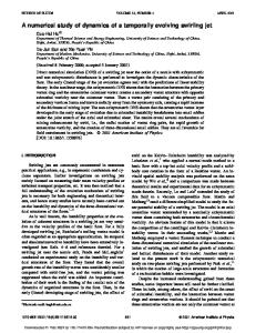
FIG. 3. The orientational correlation functions 202(r) and 220(r) together indicate the orientation of two molecules with respect to each other. 共a兲 Stacked configuration for which 202(r) and 220(r) are both positive. 共b兲 T- and L-shaped configuration for which 202(r)⬎0 and 220(r)⬍0. 共c兲 Side by side configuration in which the two rings line in a single plane beside each other. Here 202(r)⬍0 and 220(r)⬎0. 共d兲 Out-of-plane configuration for which both 202(r) and 220(r) are negative.
FIG. 2. A snapshot of 共a兲 -phase at 105 K and 共b兲 ␣-phase at 165 K obtained from the MC simulation.
peaks seen in the CCH3 – CCH3 g(r) obtained from simulation 关Fig. 1共d兲兴 may be compared to the fine structure observed in the experimental curve. This suggests that there is reasonable librational and vibrational motion of the CH3 group. An instantaneous snapshot of the simulated -toluene phase is shown in Fig. 2共a兲. The intensities of the peaks obtained from run I and Ia are not expected to agree with each other since run Ia has been carried out for a very limited number of MC steps without proper equilibration just to obtain the peak positions corresponding to the experimentally reported crystal structure. Figure 2共b兲 will be discussed later in the next section. An insight into orientational correlations among toluene in the -phase can be obtained from two correlation functions defined as21,14 ˆ 兲 2 ⫹3 共 zˆ •R ˆ 兲 2 ⫺2 典 , 202共 R 兲 ⫽ 共 1/4冑5 兲 具 3 共 zˆ1 •R 2
共5兲
220共 R 兲 ⫽ 共 1/2冑5 兲 具 3 共 zˆ1 •zˆ2 兲 2 ⫺1 典 .
共6兲
These two functions together indicate the orientation of two molecules with respect to each other at various distances of separation R. Here Rˆ is the unit vector connecting the c.o.m. of two neighboring molecules 共1 and 2兲 and zˆ 1 and zˆ 2
are the vectors perpendicular to the plane of the benzene ring of molecule 1 and 2, respectively. Figure 3 depicts the various possibilities. For a stacked configuration in which the two benzenes lie parallel to each other, 202(R) and 220(R) are both positive 关see Fig. 3共a兲兴. In a T-shaped or L-shaped arrangement of benzene rings, note that 202(R)⬎0 and 220(R)⬍0 关see Fig. 3共b兲兴. 202(R)⬍0 and 220(R)⬎0 suggests that the two rings lie in a single plane beside each other. These are shown in Fig. 3共c兲. When both 202(R) and 220(R) are negative, the orientation is as shown in Fig. 3共d兲. Figure 4 shows these correlation functions for the crys-
FIG. 4. The orientational correlation functions 202(r) and 220(r) of -toluene at 105 K. The details are same as in Fig. 1.
Downloaded 04 Jan 2005 to 130.102.2.60. Redistribution subject to AIP license or copyright, see http://jcp.aip.org/jcp/copyright.jsp
8074
J. Chem. Phys., Vol. 113, No. 18, 8 November 2000
talline -phase from runs I共continuous line兲 and Ia 共dotted– dashed line兲. It is seen that the interaction potential predicts the correct structure for the equilibrated -phase. There is reasonable agreement with the experimental crystal structure. There are some differences in 220(r) in the range: 6.0–7.3 Å and 8.6–9.1 Å. But note that these differences are really not significant since the number of neighbors at these distances 共see Fig. 1兲 are negligible. The nearest neighbor structure is characterized by 202(r)⬎0 and 220(r)⬍0 共between 4.7 and 5.3 Å兲 suggesting a T-shaped arrangement. Earlier studies of the crystalline phases of the benzene as well as simulations of the solid and liquid phases of benzene has suggested that the most favored nearest neighbor arrangement is a T-shaped configuration.14 It is also known that the T-shaped configuration is lower in energy than the stacked configuration 共in which the two rings are stacked over one another parallel to each other兲 due to the quadrupole interactions. Between 5.5 and 6.0 Å, 202(r)⬍0 and 220(r)⬎0 suggesting that the two benzene rings lie in the same plane beside each other with rings embedded in the plane. Between 6.8 and 8.0 Å, both 202(r) and 220(r) are positive suggesting a stacked 共parallel兲 configuration. The quadrupolar interactions which vary as r ⫺5 do not play a significant role at these large distances. Note that Fig. 4 should be interpreted in conjunction with Fig. 1 since the density of population at a given distance can be obtained only from the latter.
Kumar, Yashonath, and Chaplot
FIG. 5. The c.o.m.–c.o.m., Cring – Cring , Cring – CCH3 , and CCH3 – CCH3 radial distribution functions of the ␣-phase of toluene at 165 K. The solid lines are the g(r)’s obtained from the variable shape simulation 共run II兲. The dotted– dashed lines show those calculated from NVT MC run 共run IIa兲.
B. Structure of ␣-toluene at 165 K
The unit cell parameters obtained from variable shape Monte Carlo simulation 共run II兲 are listed in Table II. The initial configuration was taken to be the x-ray structure of the ␣-phase reported by Anderson et al.16 It is seen that the angle  remains close to the experimentally obtained value while other two angles are close to 90°. The unit cell lengths are within 1% of the experimental values. The volume is again found to be close to the experimental volume. Four different radial distribution functions 共rdfs兲 for the ␣-phase are shown in Fig. 5. In general the g(r)’s for the ␣-phase are more diffuse than the g(r)’s of -phase as is to be expected. A snapshot of the ␣-phase at 165 K is shown in Fig. 2共b兲. It is evident that the ordering of the toluene is different from those found in the -phase. The simulated rdfs show much better agreement with the experimental or NVT MC rdfs. Figure 6 shows a plot of the 202(r) and 220(r) for the ␣-phase. It is seen that these functions for the ␣-phase are quite different from those obtained for the low temperature -phase. The nearest neighbor configuration below a distance of 5 Å is similar to that observed for the -phase, viz., 202(r)⬎0 and 220(r)⬍0 suggesting a T-shaped orientation with respect to each other. 220(r) shows rather poor agreement in the vicinity of 6 Å indicating thereby that the rings are not in the experimentally derived orientation. Note that this is in spite of the fact that the rdfs show excellent agreement 共see Fig. 5兲. But this is because there could be several orientations which could all give the same rdfs. This is especially true since Cring – Cring do not distinguish between various carbons of the ring.
Just beyond 7 Å it is seen that 202(r) and 220(r) are both positive over a narrow range suggesting a stacked arrangement. Such an arrangement is seen around 8.3 Å as well. Stacked configuration is also seen over a narrow range between 5.2 and 5.5 Å. This suggests that in case of toluene the stacked configuration is destabilized only at the distance of closest approach 共⬍5 Å兲. In benzene, the role of the quadrupole moment is predominant. Presumably, the CH3 group in toluene interacts favorably with the ring. This seems to be responsible for the decreased role of the quadrupolar interactions in determining the orientation of the rings between neighbors beyond 5.5 Å distance.
FIG. 6. The orientational correlation functions 202(r) and 220(r) of ␣-toluene at 165 K. The details are same as in Fig. 5.
Downloaded 04 Jan 2005 to 130.102.2.60. Redistribution subject to AIP license or copyright, see http://jcp.aip.org/jcp/copyright.jsp
J. Chem. Phys., Vol. 113, No. 18, 8 November 2000
Condensed phases and solid–solid phase transition in toluene
8075
FIG. 7. The change in the c.o.m.–c.o.m. g(r) during the - to ␣-phase transition of toluene. 共a兲 The c.o.m.– c.o.m. g(r) of the starting configuration. 共b兲 After 3000 MC steps. 共c兲 After 6000 MC steps 共continuous line兲. The g(r) obtained from the run II of ␣-toluene is shown as a dotted–dashed line for comparison.
C. - to ␣-phase structural transformation
Starting with the -phase structure and a temperature of 105 K, long runs with a variable shape simulation cell at constant pressure 共run III兲 was carried out. The temperature was increased to 165 K and the c.o.m.–c.o.m. g(r) was monitored to see if there was any change in the solid phase. Figure 7 displays these rdfs at the start and after 3000 and 6000 MC steps. It is evident from the g(r) at 3000 MC steps that the structure is undergoing a transformation. During the first 4000 or 5000 MC steps, the instantaneous g(r) calculated at any given MC step was seen to be evolving. Beyond 5000 MC steps, the g(r) remained the same and did not show any further evolution or change with the MC steps. The g(r) after 6000 MC steps is plotted in Fig. 7共c兲. The c.o.m.– c.o.m. g(r) of Fig. 3 for the ␣-phase共run II兲 is also shown in the Fig. 7共c兲. It is evident that both have similar structure, namely, that of the monoclinic ␣-phase. Figure 8 shows a
plot of Cring – CCH3 g(r) at the start of simulation, after 3000 and 6000 MC steps. It is clear that the g(r) after 6000 MC steps is close to that of the ␣-phase共indicated by the dotted– dashed line兲. Figures 9 and 10 show the evolution of orientational correlation functions 202(r) and 220(r) over 6000 MC steps. These closely overlap those obtained from run III. Thus, clearly the low temperature orthorhombic -phase has transformed into the monoclinic ␣-phase, at 165 K. The simulation cell parameters of the transformed phase for run III as well as for run I and II are listed in Table II. It is seen that the lattice parameters of the ␣-phase from run III and II agree closely with each other. The relationship between the unit cell parameters of the ␣- and the -phases is as follows: a ␣ ⫽c  ,
共7兲
b ␣ ⫽b  /2,
共8兲
FIG. 8. The evolution of the Cring – CCH3 g(r) during the - to ␣-phase transition of toluene. 共a兲 The Cring – CCH3 g(r) of the starting configuration. 共b兲 After 3000 MC steps. 共c兲 After 6000 MC steps共continuous line兲. The g(r) obtained from the VS-MC run 共run II兲 of ␣-toluene is shown 共dotted–dashed line兲 for comparison.
Downloaded 04 Jan 2005 to 130.102.2.60. Redistribution subject to AIP license or copyright, see http://jcp.aip.org/jcp/copyright.jsp
8076
J. Chem. Phys., Vol. 113, No. 18, 8 November 2000
Kumar, Yashonath, and Chaplot
FIG. 9. The change in the orientation correlation function 202(r) during the - to ␣-phase transition of toluene. 共a兲 The 202(r) of the starting configuration. 共b兲 After 3000 MC steps. 共c兲 After 6000 MC steps. The dotted–dashed line shows the orientational correlation function 202(r) obtained from the VS-MC run of ␣-toluene 共run II兲.
c ␣ ⫽2 ␣  .
共9兲
There is little change in the volume of the unit cells when the structure transforms from - to the ␣-phase. The most significant change occurs in the angle  which changes from 90° to 103.9°. We attempted to characterize the - to ␣-transformation more carefully by carrying out yet another simulation, run IIIa. Here we started with the -phase at 105 K as in run III but raised the temperature in steps of 5 K until we reached 165 K. At each temperature, the system was equilibrated for 1000 MC steps and averages obtained over next 2000 MC steps. The starting configuration at any given temperature was taken from the final configuration of the previous temperature. The evolution of average intermolecular energy 具 U 典 and lattice parameters a, b, c, and  are shown in Fig. 11. It is seen that up to 140 K there is little or no change in the lattice parameters and U. The change in volume is small and hence is not plotted. Transition temperature clearly lies
between 140 and 145 K. This is in excellent agreement with the experimental range of 140–145 K for the transition temperature. The latter is based on x-ray diffraction data of Andre et al.15 Figure 11 suggests that though the volume change is small, the - to ␣-phase transformation is a firstorder transition. The fact that a change of this magnitude does occur in the simulation by a raise of just 5° 共as we will see below兲 in the temperature augurs well for the Parrinello–Rahman variable shape simulation method. Earlier when simulations were attempted on monatomic solids, the transition from fcc to hcp did not take place.5,22 In a fcc to hcp transition, modification near the third or the fourth shell of neighbors is necessary. In contrast, in toluene a modification of the first two shells—nearest neighbor and next nearest neighbor— itself occurs as is indicated by the c.o.m.–c.o.m. g(r) 共see Fig. 7兲. To the best of our knowledge this is the first time that a
FIG. 10. The change in the orientation correlation function 202(r) during the - to ␣-structural phase transition of toluene. Details are as in Fig. 9.
Downloaded 04 Jan 2005 to 130.102.2.60. Redistribution subject to AIP license or copyright, see http://jcp.aip.org/jcp/copyright.jsp
J. Chem. Phys., Vol. 113, No. 18, 8 November 2000
Condensed phases and solid–solid phase transition in toluene
8077
FIG. 12. Density of states within the harmonic approximation using the 0 K structure.
-phase by cooling were unsuccessful and that the - to ␣-phase transformation is indeed irreversible.15
FIG. 11. Variation of the 共a兲 intermolecular interaction energy U 关see Eq. 共4兲兴 and 共b兲 the simulation cell parameters a, b, and c as well as 共c兲 the angle  at various temperatures in steps of 5 K during the heating run. The transition is sharp and suggests a first-order phase transformation between 140 and 145 K. The actual points from run IIIa are shown by 〫.
E. Phonon spectra
The phonon density of states 共DOS兲 was calculated within the harmonic approximation and the external mode formalism19,23–26 by diagonalization of the dynamical matrices at 128 wave vectors in the Brillouin zone. As there are a total of 48 external mode phonon frequencies at each wave vector corresponding to the 8 molecules in the unit cell in both monoclinic and the orthorhombic structures, we sampled 128⫻48 phonon frequencies to calculate the density of states in each structure. Figure 12 shows the phonon DOS spectra for the two phases. Both phases are dynamically stable because the eigenvalues for the -phase as well as the ␣-phase are positive at T⫽0 within the harmonic approximation. The spectra are shifted to slightly lower energies for the orthorhombic phase and this leads to a higher vibrational entropy for this phase. Table III lists the vibrational mean square amplitudes along three directions in the monoclinic and orthorhombic phases obtained from within the harmonic approximation and the Monte Carlo simulation. At T⫽0, orthorhombic phase is the stable phase, within the harmonic approximation. The results from the Monte Carlo simulation for the - and the ␣-phase were obtained at 105 K and 165 K, respectively. Figure 13 shows the center-of-mass trajectory of toluene over a period of 300 MC steps, for - and ␣-phases. The change in free energy between the - and
transition has been successfully simulated in a polyatomic system in which such a large difference in magnitude of one of the cell parameters exists between the starting and the final phases and the transformation being investigated is not an order–disorder transition; obviously, simple doubling of the a, b or c does not belong to this class. However, the large change in  is nontrivial. The successful simulation of - to ␣-phase of toluene suggests that the variable shape MC and presumably MD simulations can be employed in realistic studies of crystal structure transformations of at least polyatomic systems. D. ␣- to -phase structural transformation
The ␣-toluene at 165 K was cooled to 105 K abruptly as well as gradually to see if it transformed back to the -phase. Even after repeated attempts, no such transformation was observed; the ␣-phase persisted even at low temperature with little or no change in the structure as evidenced by the various radial distribution functions and orientational correlation functions 共not shown兲. Later we found that even laboratory experiments to transform the monoclinic ␣-phase to the
TABLE III. Vibrational mean square amplitudes in the orthorhombic and monoclinic phases obtained from Monte Carlo and within the harmonic approximation.
-phase 共105 K兲 2
Monte Carlo Lattice dynamicsa
Along x, Å
Along y, Å
0.045 08 0.019 15
0.026 54 0.015 75
2
␣-phase 共165 K兲 Along z, Å 0.024 74 0.013 81
2
Along x, Å 0.063 52 0.014 51
2
Along y, Å2
Along z, Å2
0.050 15 0.015 21
0.053 37 0.016 80
These results are at T⫽100 K for both - and ␣-phases.
a
Downloaded 04 Jan 2005 to 130.102.2.60. Redistribution subject to AIP license or copyright, see http://jcp.aip.org/jcp/copyright.jsp
8078
J. Chem. Phys., Vol. 113, No. 18, 8 November 2000
Kumar, Yashonath, and Chaplot
FIG. 14. The radial distribution functions c.o.m.–c.o.m., Cring – Cring Cring – CCH3 , and CCH3 – CCH3 of liquid toluene at 240 K.
FIG. 13. Center-of-mass trajectories of toluene over a period of 300 MC steps for 共a兲 -phase at 105 K and 共a兲 ␣-phase at 165 K. Only one in ten steps have been plotted.
␣-phases, ⌬G⫽16 meV/molecule or 1.54 kJ/mol from the lattice dynamics calculation. →␣ phase change occurs at 145 K in the Monte Carlo perhaps due to anharmonicity. The reverse transition does not occur probably due to the kinetics.
The average intermolecular potential energy is found to be ⫺41.25 kJ/mol. The PV term contributes a small amount 共0.009 kJ/mol兲. The enthalpy at 240 K is therefore around 41.24 kJ/mol. Experimentally, the heat of vaporization under standard temperature and pressure conditions is 39.20 kJ/mol.27 The boiling point of toluene is 383.7 K which is much higher than 240 K at which we have carried out the simulation. The rdfs 共see Fig. 14兲 exhibit typical characteristics of any liquid. The orientational correlation functions 202(r) and 220(r) 共see Fig. 15兲 are both initially positive 共i.e., at small r兲 suggesting a stacked configuration. It appears that the presence of methyl group lends stability to the stacked configuration in spite of the presence of the quadrupolar interaction. Thus the nearest neighbor structure of the liquid
F. Liquid toluene
Toluene is known to melt at 178 K at atmospheric pressure.27 In order to the study the structure of liquid toluene, we first raised the temperature of ␣-toluene from 165 K to 500 K. The system was retained at 500 K for 3000 MC steps and subsequently cooled down to 240 K. The system was equilibrated for 1000 MC steps at 240 K and properties averaged over 2000 MC steps. The volume is somewhat higher 共162.4 Å3/molecule兲 which corresponds to a density of 0.9477 g/cm3. The density at 293.15 K is 0.8669 g/cm3.27 The coefficient of thermal expansion27 for toluene has been reported to be  ⫽1.0999⫻10⫺3 K⫺1 from which one obtains a value of 0.9547 g/cm3 共or 161.19 Å3/molecule兲 for the density at 240 K. This compares well with the computed value. The error in the computed density is 0.72%.
FIG. 15. The orientational correlation functions 202(r) and 220(r) of liquid toluene at 240 K.
Downloaded 04 Jan 2005 to 130.102.2.60. Redistribution subject to AIP license or copyright, see http://jcp.aip.org/jcp/copyright.jsp
J. Chem. Phys., Vol. 113, No. 18, 8 November 2000
phases of toluene and benzene are quite different; in benzene liquid, nearest neighbors do not assume a stacked configuration. However the number of pairs with stacked configurations in toluene is very small as is seen from the c.o.m.– c.o.m. g(r). The g(r) peaks at 6 Å and at this distance the preferred arrangement appears to be V-shaped in which the angle between the rings is around 45°.
Condensed phases and solid–solid phase transition in toluene
8079
ACKNOWLEDGMENTS
The authors thank the Council of Scientific and Industrial Research, New Delhi for partial financial support in carrying out this work. One of us 共A.V.A.K.兲 wishes to thank University Grants Commission, New Delhi for the award of a senior research fellowship. Contribution No. 1517 from the Solid State and Structural Chemistry Unit.
IV. CONCLUSIONS
In conclusion, the parameter set II of the potential proposed by Williams and Starr does reproduce the ␣-phase well. The -phase is not reproduced as well. There are several discrepancies between the nearest neighbor structure suggested by x-ray and the simulation. The c.o.m–c.o.m g(r) of the -phase and the orientational correlation function of the ␣-, as well as the -phase exhibit deviations from the experimental structure. These functions provide a much more rigorous test of the Williams and Starr potential. One of the general discrepancies of the Williams potential appears to be an overestimate of the heat of vaporization. Earlier study on benzene also found a similar trend.14 Lattice dynamical calculations suggest that within harmonic approximation the transition does not occur. It is unlikely that the parameter set I given by Williams and Starr will do as well as set II since the former does not have any electrostatic interactions. The potential of Williams and Starr reproduces the transition from the - to ␣-phase successfully. In the simulation the reverse transition does not take place. This is precisely what is observed experimentally. This appears to be the first successful simulation of a phase transformation in a polyatomic system apart from the usual order–disorder type of transformations. This study suggests that the study of the condensed phases of aromatic solids can be carried out successfully using the variable shape simulation methods and the potentials existing in the literature. The present study suggests some refinement in the existing potential. It also suggests that the six degrees of freedom for the simulation cell proposed earlier by Yashonath and Rao does not in any way restrict or inhibit the transformation. This suggests that while such a restriction prevents the rotation of the simulation cell, it does not in any way inhibit the system from transforming to any other structure that is consistent with the intermolecular potential.
A. I. Kitaigorodskii, Molecular Crystals and Molecules 共Academic, New York, 1973兲. 2 A. Gavezzotti, Acc. Chem. Res. 27, 309 共1994兲. 3 G. R. Desiraju, Crystal Engineering 共Elsevier, Amsterdam, 1989兲. 4 G. R. Desiraju and A. Gavezzotti, Acta Crystallogr., Sect. B: Struct. Sci. 45, 473 共1989兲. 5 M. Parrinello and A. Rahman, Phys. Rev. Lett. 45, 1196 共1980兲. 6 S. Yashonath and C. N. R. Rao, Mol. Phys. 54, 245 共1985兲. 7 S. Nose and M. L. Klein, Phys. Rev. Lett. 50, 1207 共1983兲. 8 M. Parrinello, A. Rahman, and P. Vasishta, Phys. Rev. Lett. 50, 1073 共1983兲. 9 S. Nose and M. L. Klein, Mol. Phys. 50, 1055 共1983兲; J. Chem. Phys. 78, 6928 共1983兲. 10 S. Yashonath and C. N. R. Rao, Chem. Phys. Lett. 119, 22 共1985兲. 11 E. Nuesy, S. Nose, and M. L. Klein, Mol. Phys. 52, 269 共1984兲. 12 S. Yashonath and C. N. R. Rao, J. Phys. Chem. 90, 2552 共1986兲. 13 A. Chakrabarti, S. Yashonath, and C. N. R. Rao, Mol. Phys. 84, 49 共1995兲. 14 S. Yashonath, S. L. Price, and I. R. McDonald, Mol. Phys. 64, 361 共1988兲. 15 D. Andre, R. Fourme, J. Bruneaux-Poulle, and L. Bosio, J. Mol. Struct. 81, 253 共1982兲. 16 M. Anderson, L. Bosio, J. Bruneaus-Poulle, and R. Fourme, J. Chim. Phys. 74, 68 共1977兲. 17 D. E. Williams and T. L. Starr, Comput. Chem. 1, 173 共1977兲. 18 D. E. Williams and S. R. Cox, Acta Crystallogr. B 40, 404 共1984兲. 19 S. L. Chaplot, Phys. Rev. B 36, 8471 共1987兲. 20 M. Metropolis, A. Rosenbluth, M. N. Rosenbluth, A. N. Teller, and E. Teller, J. Chem. Phys. 21, 1087 共1953兲. 21 O. Steinhauser, Chem. Phys. 73, 155 共1982兲. 22 M. Parrinello and A. Rahman, in Melting, Localization, and Chaos, edited by R. K. Kalia and P. Vashishta 共Elsevier, Amsterdam, 1982兲. 23 G. Venkataraman and V. C. Sahni, Rev. Mod. Phys. 42, 409 共1970兲. 24 K. R. Rao, S. L. Chaplot, P. K. Iyengar, A. H. Venkatesh, and P. R. Vijayaraghavan, Pramana 11, 251 共1978兲. 25 S. L. Chaplot, External Report, BARC, 972, 1978. 26 G. S. Pawley, in Methods of Experimental Physics, edited by K. Scold and D. Price 共Academic, New York, 1986兲, Vol. A23, p. 441. 27 CRC Handbook of Chemistry and Physics, edited by R. C. Weast 共CRC Press, Cleveland, 1976–77兲. 1
Downloaded 04 Jan 2005 to 130.102.2.60. Redistribution subject to AIP license or copyright, see http://jcp.aip.org/jcp/copyright.jsp